Table of Contents

Subscribe to Our Youtube Channel
Related Manuals for Hioki 3153


Summary of Contents for Hioki 3153
- Page 1 99 Washington Street Melrose, MA 02176 Phone 781-665-1400 Toll Free 1-800-517-8431 Visit us at www.TestEquipmentDepot.com 3153 Instruction Manual AUTOMATIC INSULATION/ WITHSTANDING HiTESTER Mar. 2017 Revised edition 15 3153A981-15 17-03H...
-
Page 2: Table Of Contents
Contents Introduction Inspection Safety Notes Notes on Use Chapter Summary Chapter 1 Overview 1.1 Product Introduction 1.2 Names and Functions of Parts 1.2.1 Front panel 1.2.2 Rubber keys 1.2.3 Rear panel 1.2.4 9615 H.V. TEST LEAD 1.2.5 REMOTE CONTROL BOX 1.3 External Dimensions Chapter 2 Testing Arrangements 2.1 Connecting the Protective Ground Terminal... - Page 3 3.3.5 Setting the Type of Test Voltage 3.3.6 Examples of Settings 3.4 Starting a Test 3.4.1 Executing a Test 3.4.2 Screening in "TEST" State 3.5 "PASS" or "FAIL" Determination 3.5.1 "PASS" State 3.5.2 Screening in "PASS" State 3.5.3 "FAIL" State 3.5.4 Screening in "FAIL"...
- Page 4 5.5.1 "PASS" State 5.5.2 Screening in "PASS" State 5.5.3 "FAIL" State 5.5.4 Screening in "FAIL" State 5.6 Automatic Discharge Function Chapter 6 Program Mode Testing Method 6.1 Program Mode Display 6.2 Displaying the "READY" State 6.2.1 Key-lock Function 6.3 Program Setting State 6.3.1 Examples of Settings 6.4 Program-File Loading 6.5 Starting a Test...
- Page 5 Chapter 8 Saving/loading Preset Values 8.1 Saving Preset Values 8.1.1 Procedure for Saving Data 8.1.2 Example of Saving 8.2 Loading Preset Values 8.2.1 Procedure for Loading Data 8.2.2 Example of Loading Chapter 9 External Interface 9.1 External I/O Terminal 9.1.1 Signal Line 9.1.2 Example of Input Signal Connection 9.1.3 Example of Output Signal Connection 9.1.4 Inter-lock Function...
- Page 6 11.1.3 Timer Section 11.1.4 Interface 11.1.5 Program Function 11.1.6 Other Functions 11.2 General Specifications Chapter 12 Maintenance and Inspection 12.1 Maintenance and Service 12.2 Fuse Replacement 12.3 Troubleshooting 12.4 Displaying Errors 12.5 Removing the Lithium Battery 12.6 Resetting the System Appendix APPENDIX 1 Appendix 1 9613 REMOTE CONTROL BOX (SINGLE)
- Page 8 Warranty HIOKI cannot be responsible for losses caused either directly or indirectly by the use of the 3153 with other equipment, or if ownership is transferred to a third party. Before using the product, make sure that the insulation on the leads is undamaged NOTE and that no bare conductors are improperly exposed.
-
Page 9: Safety Notes
_____________________________________________________________________________________________ Safety Notes This product is designed to conform to IEC 61010 Safety Standards, and has been thoroughly tested for safety prior to shipment. However, WARNING mishandling during use could result in injury or death, as well as damage to the product. Be certain that you understand the instructions and precautions in the manual before use. - Page 10 _____________________________________________________________________________________________ Measurement categories To ensure safe operation of measurement products, IEC 61010 establishes safety standards for various electrical environments, categorized as CAT II to CAT IV, and called measurement categories. CAT II Primary electrical circuits in equipment connected to an AC electrical outlet by a power cord (portable tools, household appliances, etc.) CAT II covers directly measuring electrical outlet receptacles.
- Page 11 _____________________________________________________________________________________________ Accuracy The specifications in this manual include figures for "measurement accuracy" when referring to digital measuring instruments, and for "measurement tolerance" when referring to analog instruments. f.s. (maximum display or scale value, or length of scale) Signifies the maximum display (scale) value or the length of the scale (in cases where the scale consists of unequal increments or where the maximum value cannot be defined).
-
Page 12: Notes On Use
_____________________________________________________________________________________________ Notes on Use Follow these precautions to ensure safe operation and to obtain the full benefits of the various functions. To avoid electric shock, do not remove the product's case. The internal components of the product carry high voltages and may become very DANGER hot during operation. -
Page 13: Chapter Summary
_____________________________________________________________________________________________ Chapter Summary Chapter 1 Overview Describes an overview, features, and the names and functions of the parts of the product. Chapter 2 Testing Arrangements Describes particulars of testing arrangements. Chapter 3 Withstand Voltage Mode Testing Method Describes the procedures for setting the withstand-voltage mode testing, testing method, and test decisions. -
Page 14: Chapter 1 Overview
_____________________________________________________________________________________________ Chapter 1 Overview 1.1 Product Introduction (1) Easy testing conforming to standards With the unit insulation-resistance and withstand-voltage tests based on a wide variety of standards can be performed. Accurate test results can be obtained by comparative screening functions that use upper- and lower-limit values, timer functions, and ramp up/down timer functions that control test- voltage increases/decreases. - Page 15 CONTROL BOX (dual-hand) can be connected to the external switch terminal to perform 3153 start/stop control. (7) External I/O The external I/O terminal generates signals according to the state of the 3153. It can be used to feed signals for the key. START STOP...
-
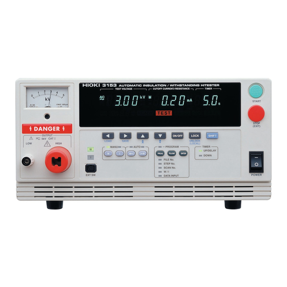
Page 16: Names And Functions Of Parts
(However, it does not light during time testing when insulation-resistance test termination mode is set to 0 [initial setting].) 11 Main power switch Powers the 3153 product on or off. 12 STOP key Normally used to terminate a test. -
Page 17: Rubber Keys
_____________________________________________________________________________________________ 1.2.2 Rubber keys Moves the flashing cursor. The switching range is preset before shipment: Withstand-voltage test: Test-voltage value ⇔ Upper-limit value ⇔ Lower-limit value ⇔ Test time ⇔ Ramp-up time ⇔ Ramp-down time ⇔ Test-voltage type Insulation-resistance test: Test-voltage value ⇔ Lower-limit value ⇔ Upper-limit value ⇔ Test time ⇔... -
Page 18: Rear Panel
RS-232C terminal Used for remote control with RS-232C. External I/O For output of 3153 state and input of start and stop signals. terminal Used for remote control with GP-IB. GP-IB terminal HIGH terminal A high-voltage terminal for voltage output. Connected to the HIGH terminal on the front panel. -
Page 19: 9615 H.v. Test Lead
_____________________________________________________________________________________________ 1.2.4 9615 H.V. TEST LEAD The vinyl shield on the 9615 H.V. TEST LEAD alligator clip is not high voltage insulated. Do not touch when high voltage is applied. DANGER High-voltage side (red) Low-voltage side (black) Alligator clip Connect to a test point on the tested object. Connect to the HIGH terminal on the unit. -
Page 20: Remote Control Box
_____________________________________________________________________________________________ 1.2.5 REMOTE CONTROL BOX 9613 REMOTE CONTROL BOX (SINGLE) 9614 REMOTE CONTROL BOX (DUAL) Used to enable remote-control operation. When this switch is ON, OPERATE switch keys for remote control are active. START STOP START key Works in the same manner as the key on the unit. -
Page 21: External Dimensions
_____________________________________________________________________________________________ 1.3 External Dimensions 320 ±2 m m ______________________________________________________________________________________________ 1.3 External Dimensions... -
Page 22: Chapter 2 Testing Arrangements
_____________________________________________________________________________________________ Chapter 2 Testing Arrangements 2.1 Connecting the Protective Ground Terminal To avoid electric shock, be sure to connect the protective ground terminal to a grounded conductor. WARNING To avoid electric shock, connect the protective ground terminal to a grounded conductor before making any other connections. 1. -
Page 23: Wearing Rubber Gloves
Lead, etc. 1. To avoid electrocution, always wear high-voltage protective rubber gloves when using this product. 2. Contact your dealer or Hioki representative to help you look for high- voltage protective rubber gloves. 2.3 Connecting the External I/O Connector Connect the external I/O connector before turning on the power. If the external I/O connector is installed or removed following startup, malfunction may result. -
Page 24: Power Cord Connection
_____________________________________________________________________________________________ 2.4 Power Cord Connection Before turning the product on, make sure the source voltage matches that indicated on the product's power connector. Connection to an WARNING improper supply voltage may damage the product and present an electrical hazard. To avoid electrical accidents and to maintain the safety specifications of this instrument, connect the power cord provided only to a 3- contact (two-conductor + ground) outlet. -
Page 25: Powering On And Off The Unit
_____________________________________________________________________________________________ 2.5 Powering On and Off the Unit Before turning on the power, make sure that the voltage of the power supply being used matches the supply voltage indicated on the rear WARNING panel of the unit. If an attempt is made to use an improper supply voltage, there is danger of damage to this unit and of life-threatening risk to the operator. - Page 26 _____________________________________________________________________________________________ (1) Powering on the unit 1. Turn the main power switch to ON(l) . Main power switch 2. The model name and version number are displayed as below: Software version Model name "Version 1.00" is displayed. Interface "RS-232C 9600 bps" is displayed. "rS.0"...
-
Page 27: Connecting The 9615 H.v. Test Lead
Hioki representative for repair. To avoid electric shock, make sure the 9615 H.V. TEST LEAD is securely connected before starting a test, as a loose test lead can cause a hazard when a voltage is output. -
Page 28: Connecting The Remote Control Box
_____________________________________________________________________________________________ 2.7 Connecting the REMOTE CONTROL BOX To prevent electrical shock, turn off the power unit, make sure that there is no high voltage being applied to the output, confirm the WARNING following 3 items, and connect the 9615 H.V. TEST LEAD. (1) The analog voltmeter reads 0 kV. -
Page 29: Installation Of The Unit
_____________________________________________________________________________________________ 2.8 Installation of the Unit Temperature: 0 to 40℃ Humidity: 80% RH or less (no condensation) Avoid the following locations: ・Subject to direct sunlight. ・Subject to high levels of dust, steam, or corrosive gases (Avoid using the equipment in an environment containing corrosive gases (e.g., H S, SO , and CI ) or substances that generate harmful gasses (e.g., organic... -
Page 30: Connection To The Measured Equipment
_____________________________________________________________________________________________ 2.9 Connection to the Measured Equipment Observe the following precautions to avoid electric shock. Make sure that no high voltage is being applied to the output, confirm DANGER the following items, and connect the H.V. TEST LEAD. (1) The analog voltmeter reads 0 kV. (2) The lamp is OFF. -
Page 31: Startup Inspection
_____________________________________________________________________________________________ 2.10 Startup Inspection To ensure safe testing, check the following before starting operation: (1) Breaking current (withstand-voltage mode) 1. Prepare a resistor with a resistance smaller than that of the calculation result from the output voltage and test upper-limit value (breaking current) that are preset in the withstand-voltage test. -
Page 32: Chapter 3 Withstand Voltage Modetesting Method
_____________________________________________________________________________________________ Chapter 3 Withstand Voltage Mode Testing Method This chapter describes how to set withstand-voltage mode test conditions and the proper testing procedure. Read chapter 2, and make the necessary preparations for testing. Press the key to enter withstand-voltage mode. (The W lamp above the key to the left lights.) Flashing Note that the output waveform may be distorted when conducting an AC withstand... -
Page 33: Withstand Voltage Mode Display
_____________________________________________________________________________________________ 3.1 Withstand Voltage Mode Display 「READY 状態」 state READY ・The unit is ready for starting a test. The lamp is turned on. READY ・Press the key while in the READY state. START ・Press the key while in SETTING state. ・Press keys to display the Optional Function Setting screen. - Page 34 _____________________________________________________________________________________________ START key 「READY 状態」 state TEST See Section 3.4.2 ・When the unit is in the TEST state, the lamp is lit. This indicates that a test is in TEST progress. ・The measured-current value is compared with the upper- and lower-limit values. If the measured-current value deviates from these values, the unit shifts to the FAIL state and the test is terminated.
-
Page 35: Displaying The "Ready" State
_____________________________________________________________________________________________ 3.2 Displaying the "READY" State In the READY state, the unit is always ready to start a test. The READY lamp remains lit to indicate the READY state. Saving and loading for setting data and the setting of optional functions are made following the READY state. -
Page 36: Key-Lock Function
_____________________________________________________________________________________________ 3.2.1 Key-lock Function It inactivates all keys except the key, key, and the range switch. START STOP lamp is lit while the key-lock function is active. KEYLOCK Use this function when you do not want to change the test mode or test settings. -
Page 37: Setting" State
_____________________________________________________________________________________________ 3.3 "SETTING" State To set or change test settings, switch to the SETTING state. In the SETTING state, the light goes out and tests cannot start. READY NOTE In the withstand-voltage mode READY state and "test setting state," although the test-voltage value is displayed, that voltage is not being output. -
Page 38: Setting The Test Voltage Value
_____________________________________________________________________________________________ 3.3.1 Setting the Test Voltage Value Set a test-voltage value. The test will not start if the load current value is large and the output voltage does not reach ±5% of the set test voltage. flashes.) If the output voltage fails to reach the test voltage within TEST approximately 5 seconds after completion of the ramp-up time, the unit will change to the FAIL state and the test will be terminated. -
Page 39: Setting The Upper (Lower) Limit Value
_____________________________________________________________________________________________ 3.3.2 Setting the Upper (Lower) Limit Value Upper-limit value Upper (Lower) Limit Value: 20 mA 1. If no flashing cursor is displayed in the withstand-voltage mode READY state, press either the / key to display the cursor in the upper (lower)- limit value position. -
Page 40: Setting The Test Time
_____________________________________________________________________________________________ 3.3.3 Setting the Test Time Test Time: 60.0 s Test Time: OFF 1. If no flashing cursor is displayed in the withstand-voltage mode READY state, press either the / key to display the cursor in the test time position. 2. -
Page 41: Setting Of The Ramp Timer
_____________________________________________________________________________________________ 3.3.4 Setting of the Ramp Timer In this unit, the time to increase the voltage until it reaches the set test voltage (ramp-up time) and the time to decrease the voltage upon completion of the test time (ramp-down time) can be set. flashes during the ramp- TEST up time and the ramp-down time. -
Page 42: Setting The Type Of Test Voltage
_____________________________________________________________________________________________ 3.3.5 Setting the Type of Test Voltage In the withstand-voltage mode, the following types of test voltages can be selected: AC 50 Hz For AC withstand-voltage tests. The frequency of the test voltage is 50 Hz. For AC withstand-voltage tests. The frequency of the test AC 60 Hz voltage is 60 Hz. -
Page 43: Examples Of Settings
Lower-limit value: OFF Test time: 60.0 s Ramp-up time: 10 s Ramp-down time: OFF Test-voltage type: AC 60 Hz The 3153 is in the READY state in withstand-voltage mode. Values currently set Values to be set Test-voltage value 1.50 kV Test-voltage value 2.00 kV... - Page 44 _____________________________________________________________________________________________ (2) Setting the test-voltage value In this example, the value is 1.50 kV Using the / keys, set the comparative voltage value to 2.00 kV To change the value by , press / keys. 0.01 kV To change the value by , press keys.
- Page 45 _____________________________________________________________________________________________ (5) Setting the test time Using the key, move the flashing cursor to the test time. In this example, change the test time from 120 s 60.0 s (6) Setting the ramp-up time Using the key, move the flashing cursor to the ramp-up time. (...
- Page 46 _____________________________________________________________________________________________ (8) Setting a test-voltage type Press the key to move the flashing cursor to the AC or DC. In this example, change the output voltage range from AC 50 Hz AC 60 Hz using / keys. Pressing the / keys changes the display as follows: →...
-
Page 47: Starting A Test
_____________________________________________________________________________________________ 3.4 Starting a Test The flowchart below explains how a test is carried out. 「READY 状態」での設定 Setting the test parameters READY state "SETTING" State See Section 3.3 Key-lock Function See Section 3.2.1 Optional Function See Chapter 7 「READY 状態」での設定 Starting a Test See Section 3.4.1 Press the... - Page 48 _____________________________________________________________________________________________ 1. Press the key when is lit. START READY The unit will change to the TEST status and a test will start. and the TEST lamp are lit in the TEST state. DANGER 2. In the following cases, tests are terminated, and , and UPPER LOWER...
-
Page 49: Screening In "Test" State
_____________________________________________________________________________________________ 3.4.2 Screening in "TEST" State Indicates the voltage value being output. Measured voltage value Upper-limit value The symbol appears when the upper-limit value is set, icon and Lower- and the symbol appears when the lower-limit value is limit value icon set. -
Page 50: Pass" Or "Fail" Determination
_____________________________________________________________________________________________ 3.5 "PASS" or "FAIL" Determination 3.5.1 "PASS" State Even when a test has been terminated, there may still be voltage in the output-voltage terminal. Before touching the output-voltage terminal, WARNING H.V. TEST LEAD, or tested object, make sure that no high voltage is being applied to the output, confirm the following items. -
Page 51: Screening In "Pass" State
_____________________________________________________________________________________________ 3.5.2 Screening in "PASS" State Measured Indicates the voltage in the PASS state. voltage value Upper-limit value The symbol appears when the upper-limit value is set, icon and Lower- and the symbol appears when the lower-limit value is limit value icon set. -
Page 52: Fail" State
_____________________________________________________________________________________________ 3.5.3 "FAIL" State Even when a test has been terminated, there may still be voltage in the output-voltage terminal. Before touching the output-voltage terminal, WARNING H.V. TEST LEAD, or tested object, make sure that no high voltage is being applied to the output, confirm the following items. (1) The analog voltmeter reads 0 kV. - Page 53 _____________________________________________________________________________________________ Flow of FAIL determination Testing time when it set up Ramp-up time Output voltage 0.03 kV AC or 0.06 kV DC Time Flashing ( UPPER LOWER ) TEST Flashing DANGER Lamp 1. Press the key to start a test. START flashes until the output voltage reaches the set test voltage.
-
Page 54: Screening In "Fail" State
_____________________________________________________________________________________________ 3.5.4 Screening in "FAIL" State Measured voltage Indicates the voltage in the FAIL state. value Upper-limit value The symbol appears when the upper-limit value is set, icon and Lower- and the symbol appears when the lower-limit value is set. limit value icon Measured current Indicates the current flowing between the HIGH and LOW... -
Page 55: Automatic Discharge Function
_____________________________________________________________________________________________ 3.6 Automatic Discharge Function When a test object that contains a capacity component is subjected to a withstand-voltage test, the object might remain electrically charged, thereby causing an electric shock. This unit is equipped with a function to discharge residual electricity upon termination of the withstand-voltage test (discharge resistance: 726 kΩ). -
Page 56: Chapter 4 Insulation Resistance Mode Testing Method
_____________________________________________________________________________________________ Chapter 4 Insulation Resistance Mode Testing Method This chapter describes how to set insulation-resistance mode test conditions and the proper testing procedure. Read chapter 2, and make the necessary preparations for testing. Press the key to enter insulation-resistance mode. (The I lamp above the key to the left lights.) Flashing ・Choose the insulation resistance test termination mode (see "7.11 Insulation... -
Page 57: Insulation Resistance Mode Display
_____________________________________________________________________________________________ 4.1 Insulation Resistance Mode Display 「READY 状態」 state READY ・The unit is ready for starting a test. The lamp is turned on. READY ・Press the key while in the READY state. START ・Press the key while in SETTING state. ・Press keys to display the Optional Function Setting screen. - Page 58 _____________________________________________________________________________________________ START key 「READY 状態」 state TEST See Section 4.4.2 ・When the unit is in the TEST state, the lamp is lit. This indicates that a test is in TEST progress. ・Compares the upper- and lower-limit measured resistance values. If the measured resistance value deviates from either of these values once the test time has elapsed, the unit shifts to the FAIL state.
-
Page 59: Displaying The "Ready" State
_____________________________________________________________________________________________ 4.2 Displaying the "READY" State In the READY state, the unit is always ready to start a test. The READY lamp remains lit to indicate the READY state. Saving and loading for setting data and the setting of optional functions are made following the READY state. -
Page 60: Key-Lock Function
_____________________________________________________________________________________________ 4.2.1 Key-lock Function It inactivates all keys except the key, key, and the range switch. START STOP lamp is lit while the key-lock function is active. KEYLOCK Use this function when you do not want to change the test mode or test settings. -
Page 61: Setting" State
_____________________________________________________________________________________________ 4.3 "SETTING" State To set or change test settings, switch to the SETTING state. In the SETTING state, the light goes out and tests cannot start. READY NOTE In the insulation-resistance mode READY state and "test setting state," although the test-voltage value is displayed, that voltage is not being output. -
Page 62: Setting The Test Voltage Value
_____________________________________________________________________________________________ 4.3.1 Setting the Test Voltage Value The test-voltage value can be set in the range of 50 V to 1,200 V in 1-V steps. Test-voltage value: 1000 V 1. If no flashing cursor is displayed in the insulation-resistance mode READY state, press either the / key to display the cursor in the test- voltage value position. -
Page 63: Setting The Lower (Upper) Limit Value
_____________________________________________________________________________________________ 4.3.2 Setting the Lower (Upper) Limit Value Lower-limit value Lower Limit Value: 10 MΩ 1. If no flashing cursor is displayed in the insulation-resistance mode READY state, press either the / key to display the cursor in the lower (upper)-limit value position. - Page 64 _____________________________________________________________________________________________ Upper- or lower-value Setting range (MΩ) Setting resolution (MΩ) 0.10 to 9.99 0.01 10.0 to 99.9 100 to 9999 Measurement resistance value Measurement range (MΩ) Measurement resolution (MΩ) 0.100 to 1.049 0.001 1.05 to 10.49 0.01 10.5 to 104.9 105 to 9999 Test voltages (reference values), lower-limit values, and measurement ranges Test voltage...
-
Page 65: Setting The Test Time
_____________________________________________________________________________________________ 4.3.3 Setting the Test Time Test Time: 10.0 s Test Time: OFF 1. If no flashing cursor is displayed in the insulation-resistance mode READY state, press either the / key to display the cursor in the test time position. 2. -
Page 66: Setting The Delay Time
_____________________________________________________________________________________________ 4.3.4 Setting the Delay Time Time during which screening is not performed from the start of a test (delay time) can be set. This is effective when a test object contains a capacity load. Delay time: 3.0 s Delay time: OFF 1. -
Page 67: Examples Of Settings
Test-voltage value: 500 V Lower-limit value: 100 MΩ Upper-limit value: OFF Test time: 5.0 s Delay time: 0.5 s The 3153 is in the READY state in insulation-resistance mode. Values currently set Values to be set Test-voltage value 1000 V... - Page 68 _____________________________________________________________________________________________ (3) Setting an lower-limit value Press the key to move the flashing cursor to the lower-limit value. In this example, switch from using the / keys. 10.0 MΩ 100 MΩ To change the lower-limit value, press / keys. Press the keys, key.
- Page 69 _____________________________________________________________________________________________ (5) Setting the test time Using the key, move the flashing cursor to the test time. In this example, change the test time from 20.0 s 5.0 s (6) Setting the delay time Using the key, move the flashing cursor to the delay time.( lamp DELAY is lit.)...
-
Page 70: Starting A Test
_____________________________________________________________________________________________ 4.4 Starting a Test The flowchart below explains how a test is carried out. 「READY 状態」での設定 Setting the test parameters READY state "SETTING" State See Section 4.3 See Section 4.2.1 Key-lock Function Optional Function See Chapter 7 「READY 状態」での設定 Starting a Test See Section 4.4.1 Press the... -
Page 71: Executing A Test
_____________________________________________________________________________________________ 4.4.1 Executing a Test To avoid electric shock, make sure that no high voltage is being applied to the output, confirm the following items, and output voltage. DANGER (1) The analog voltmeter reads 0 kV. (2) The lamp is OFF. DANGER (3) The lamp is lit (it is off in the Double Action mode). -
Page 72: Screening In "Test" State
_____________________________________________________________________________________________ 4.4.2 Screening in "TEST" State Measured Indicates the voltage value being output. voltage value The symbol appears when the upper-limit value is set, Upper-limit value icon and Lower- and the symbol appears when the lower-limit value is limit value icon set. -
Page 73: Pass" Or "Fail" Determination
_____________________________________________________________________________________________ 4.5 "PASS" or "FAIL" Determination 4.5.1 "PASS" State Even when a test has been terminated, there may still be voltage in the output-voltage terminal. Before touching the output-voltage terminal, WARNING H.V. TEST LEAD, or tested object, make sure that no high voltage is being applied to the output, confirm the following items. - Page 74 _____________________________________________________________________________________________ Flow of PASS determination Electric Delay time Test-voltage (Undetermined period) discharge time 60 V DC Testing time when it set up START DANGER Lamp 1. Press the key to start a test. START 2. A voltage is output until the test time elapses and the resistance is measured.
-
Page 75: Screening In "Pass" State
_____________________________________________________________________________________________ 4.5.2 Screening in "PASS" State Measured Indicates the voltage in the PASS state. voltage value Upper-limit value The symbol appears when the upper-limit value is set, icon and Lower- and the symbol appears when the lower-limit value is limit value icon set. -
Page 76: Fail" State
_____________________________________________________________________________________________ 4.5.3 "FAIL" State Even when a test has been terminated, there may still be voltage in the output-voltage terminal. Before touching the output-voltage terminal, WARNING H.V. TEST LEAD, or tested object, make sure that no high voltage is being applied to the output, confirm the following items. (1) The analog voltmeter reads 0 kV. - Page 77 _____________________________________________________________________________________________ Flow of FAIL determination Electric Delay time Test voltage (Undetermined period) discharge time 60 V DC Testing time when it set up START ( ) UPPER LOWER DANGER Lamp 1. Press the key to start a test. START 2. A voltage continues to be output until the test time elapses and measure resistance.
-
Page 78: Screening In "Fail" State
_____________________________________________________________________________________________ 4.5.4 Screening in "FAIL" State Indicates the voltage in the FAIL state. Measured voltage value Upper-limit value The symbol appears when the upper-limit value is set, icon and Lower- and the symbol appears when the lower-limit value is limit value icon set. -
Page 79: Automatic Discharge Function
_____________________________________________________________________________________________ 4.6 Automatic Discharge Function When a test object that contains a capacity component is subjected to a insulation-resistance test, the object might remain electrically charged, thereby causing an electric shock. This unit is equipped with a function to discharge residual electricity upon termination of the insulation-resistance test (discharge resistance: 726 kΩ). -
Page 80: Chapter 5 Auto Test Mode Testing Method
_____________________________________________________________________________________________ Chapter 5 Auto Test Mode Testing Method This chapter describes how to set auto test mode test conditions and the proper testing procedure. Read chapter 2, and make the necessary preparations for testing. This mode has two types: (1) W I mode Tests for withstand voltage, then insulation resistance. -
Page 81: Auto Test Mode Display
_____________________________________________________________________________________________ 5.1 Auto Test Mode Display 「READY 状態」 state READY ・The unit is ready for starting a test. The lamp is turned on. READY ・W I (Withstand-voltage test Insulation-resistance test) mode: the unit is in the READY state for withstand-voltage testing. ・I W (Insulation-resistance test Withstand-voltage test) mode: the unit is in the READY state for insulation-resistance testing. - Page 82 _____________________________________________________________________________________________ START key 「READY 状態」 state TEST See Section 5.4.2 ・When the unit is in the TEST state, the lamp is lit. This indicates that a test is in progress. TEST ・When performing a withstand-voltage test, compares the measured voltage value and the measured current value set in withstand-voltage mode SETTING state.
-
Page 83: Displaying The "Ready" State
_____________________________________________________________________________________________ 5.2 Displaying the "READY" State In the READY state, the unit is always ready to start a test. The READY lamp remains lit to indicate the READY state. You can make settings for each test type in a variety of modes. (See chapter 3 and chapter 4) The settings for W I mode are the same as those for withstand-voltage mode. -
Page 84: Key-Lock Function
_____________________________________________________________________________________________ 5.2.1 Key-lock Function It inactivates all keys except the key, key, and the range switch. START STOP lamp is lit while the key-lock function is active. KEYLOCK Use this function when you do not want to change the test mode or test settings. -
Page 85: Setting" State
_____________________________________________________________________________________________ 5.3 "SETTING" State In Auto test mode, test settings cannot be changed. To change test settings, the withstand-voltage and insulation-resistance modes must be in the SETTING state. (See Section 3.3 and 4.3) After you have made the various test settings, select Auto test mode. W→I I→W Make withstand-voltage mode... -
Page 86: Starting A Test
_____________________________________________________________________________________________ 5.4 Starting a Test The flowchart below explains how a test is carried out. 「READY 状態」での設定 Setting the test parameters Make withstand-voltage test settings in withstand-voltage mode. (See chapter 3.) Make insulation-resistance test settings in insulation-resistance mode. (See chapter 4.) 「READY 状態」での設定... -
Page 87: Executing A Test
_____________________________________________________________________________________________ 5.4.1 Executing a Test To avoid electric shock, make sure that no high voltage is being applied to the output, confirm the following items, and output voltage. DANGER (1) The analog voltmeter reads 0 kV. (2) The lamp is OFF. DANGER (3) The lamp is lit (it is off in the Double Action mode). -
Page 88: Screening In "Test" State
_____________________________________________________________________________________________ 5.4.2 Screening in "TEST" State (1) When performing a withstand-voltage test: Similar to the withstand-voltage mode TEST state. (See Section 3.4.2) (2) When performing an insulation-resistance test: Similar to the insulation-resistance mode TEST state. (See Section 4.4.2) Danger lamp Indicates that a voltage is being output. -
Page 89: Pass Or Fail Determination
_____________________________________________________________________________________________ 5.5 PASS or FAIL Determination 5.5.1 "PASS" State Even when a test has been terminated, there may still be voltage in the output-voltage terminal. Before touching the output-voltage terminal, WARNING H.V. TEST LEAD, or tested object, make sure that no high voltage is being applied to the output, confirm the following items. - Page 90 _____________________________________________________________________________________________ Flow of PASS determination W I mode Insulation Ramp-down Ramp-up withstand-voltage resistance Test voltage time time test time test time 0.03 kV AC or 0.06 kV DC 60 VDC Flashing Flashing DANGER Lamp DANGER Lamp DANGER Lamp 140 ms I W mode Test voltage Insulation...
-
Page 91: Screening In "Pass" State
_____________________________________________________________________________________________ 5.5.2 Screening in "PASS" State (1) W I mode Similar to the insulation-resistance mode TEST state. (See Section 4.5.2) (2) I W mode Similar to the withstand-voltage mode TEST state. (See Section 3.5.2) Danger lamp Indicates that a voltage is being output. The lamp stays on during the test. The lamp will also light if a voltage exceeding the safety voltage (approximately AC 0.03 kV (AC withstand-voltage test)) or approximately DC 60 V (DC withstand-voltage test or insulation-resistance test) remains... -
Page 92: Fail" State
_____________________________________________________________________________________________ 5.5.3 "FAIL" State Even when a test has been terminated, there may still be voltage in the output-voltage terminal. Before touching the output-voltage terminal, WARNING H.V. TEST LEAD, or tested object, make sure that no high voltage is being applied to the output, confirm the following items. (1) The analog voltmeter reads 0 kV. - Page 93 _____________________________________________________________________________________________ If a current double to the preset upper-limit value is detected while performing a NOTE withstand-voltage test, the voltage is immediately blocked by the insulation circuit, resulting in an UPPER FAIL. In such cases, the measured current value is not displayed correctly. When the optional "Insulation Resistance Measurement Range"...
-
Page 94: Screening In "Fail" State
_____________________________________________________________________________________________ 5.5.4 Screening in "FAIL" State (1) When performing a withstand-voltage test: Similar to the withstand-voltage mode TEST state. (See Section 3.5.4) (2) When performing an insulation-resistance test: Similar to the insulation-resistance mode TEST state. (See Section 4.5.4) Danger lamp Indicates that a voltage is being output. -
Page 95: Automatic Discharge Function
_____________________________________________________________________________________________ 5.6 Automatic Discharge Function When a test object that contains a capacity component is subjected to a withstand-voltage test and insulation-resistance test, the object might remain electrically charged, thereby causing an electric shock. This unit is equipped with a function to discharge residual electricity upon termination of the withstand-voltage test (discharge resistance: 726 kΩ). -
Page 96: Chapter 6 Program Mode Testing Method
_____________________________________________________________________________________________ Chapter 6 Program Mode Testing Method This chapter describes program setting and testing methods in the program mode. Read chapter 2, and make the necessary preparations for testing. Press the key to enter program mode. (The lamp above the key PROG lights.) Flashing... -
Page 97: Program Mode Display
_____________________________________________________________________________________________ 6.1 Program Mode Display 「READY 状態」 state READY ・The unit is ready for starting a test. The lamp is turned on. READY ・Press the key while in the READY state. START ・Press the key while in Program setting state. ENTER ・Press keys to display the Optional Function Setting screen. - Page 98 _____________________________________________________________________________________________ START key 「READY 状態」 state TEST See Section 6.5.2 ・When the unit is in the TEST state, the lamp is lit. This indicates that a test is in TEST progress. ・The measured current and resistance values are compared with the lower-and upper-limit values.
-
Page 99: Displaying The "Ready" State
_____________________________________________________________________________________________ 6.2 Displaying the "READY" State In the READY state, the unit is always ready to start a test. The READY lamp remains lit to indicate the READY state. ・When you enter the program mode by pressing the key, the step-1 PROG settings of the file that was loaded previously are displayed. -
Page 100: Key-Lock Function
_____________________________________________________________________________________________ 6.2.1 Key-lock Function It inactivates all keys except the key, key, and the range switch. START STOP lamp is lit while the key-lock function is active. KEYLOCK Use this function when you do not want to change the test mode or test settings. -
Page 101: Program Setting State
_____________________________________________________________________________________________ 6.3 Program Setting State To edit, change, or confirm the program file, enter the Program setting state. In the program setting state, is not lit, and the test cannot be started. READY NOTE When the program mode is used, although the test-voltage value is displayed in the READY state or "program setting state,"... - Page 102 _____________________________________________________________________________________________ 5. When the key is pressed, the lamp lights up. ENTER STEP No. 6. The step number flashes. Select the number of the step to be edited or changed using the / keys. Press the key to proceed to the next setting. If the key is ENTER STOP...
- Page 103 _____________________________________________________________________________________________ 9. When the key is pressed, the lamp lights up. Using the W key ENTER or I key, select a withstand-voltage test or insulation-resistance test to be conducted. To terminate the program test in this step, select OFF using the ON/OFF key.
-
Page 104: Examples Of Settings
_____________________________________________________________________________________________ 6.3.1 Examples of Settings This is a description of the procedure for making settings for a program test under the conditions specified below. Create a program for conducting a test in the following order and under the following conditions: Step 1. - Page 105 _____________________________________________________________________________________________ (2) Setting the file number Select the number of the file to be edited, and set the scanner mode. In this example, the file number shown is 1. Change the file number to using the keys. As the scanner is not used, move the flashing cursor using the keys, and set the scanner to using the / keys.
- Page 106 _____________________________________________________________________________________________ (6) Setting test conditions in step 1 Set the conditions of the test to be conducted in step 1. The DATA INPUT lamp will light up. Move the flashing cursor using the / keys, and set the conditions using the / keys.
- Page 107 _____________________________________________________________________________________________ (9) Setting test conditions in step 2 Set the conditions of the test to be conducted in step 2. Test type: AC50 Hz Test-voltage value: 1.5 kV Upper-limit value: 20 mA Lower-limit value: OFF Test time: 10.0 s Ramp-up time: 5.0 s Ramp-down time: OFF When the test conditions have been set, press the key to finalize the...
- Page 108 _____________________________________________________________________________________________ (12) Setting the test conditions in step 3 Set the conditions of the test to be conducted in step 3. Test type: DC Test-voltage value: 2.0 kV Upper-limit value: 10 mA Lower-limit value: OFF Test time: 3.0 s Ramp-up time: OFF Ramp-down time: OFF When the test conditions have been set, press the key to finalize the...
-
Page 109: Program-File Loading
_____________________________________________________________________________________________ 6.4 Program-File Loading Loads a file that has been created or edited, so that it can be executed. 1. Press the key in the READY state. PG.LOAD 2. Set the number of the file to be loaded using the / keys. -
Page 110: Starting A Test
_____________________________________________________________________________________________ 6.5 Starting a Test The flowchart below explains how a test is carried out. 「READY 状態」での設定 Creating a file See Section 6.3 Create a file for performing program tests in the program mode. Press the key in the program-mode READY state, and create or edit a file in the ENTER "program setting window."... -
Page 111: Executing A Test
_____________________________________________________________________________________________ 6.5.1 Executing a Test To avoid electric shock, observe the following precautions to avoid electric shock. DANGER Make sure that no high voltage is being applied to the output, confirm the following items, and output voltage. (1) The analog voltmeter reads 0 kV. (2) The lamp is OFF. -
Page 112: Screening In "Test" State
_____________________________________________________________________________________________ 6.5.2 Screening in "TEST" State (1) When performing a withstand-voltage test: Similar to the withstand-voltage mode TEST state. (See Section 3.4.2) Step number (2) When performing an insulation-resistance test: Similar to the insulation-resistance mode TEST state. (See Section 4.4.2) Step number Danger lamp Indicates that a voltage is being output. -
Page 113: Pass Or Fail Determination
_____________________________________________________________________________________________ 6.6 PASS or FAIL Determination 6.6.1 "PASS" State Even when a test has been terminated, there may still be voltage in the output-voltage terminal. Before touching the output-voltage terminal, WARNING H.V. TEST LEAD, or tested object, make sure that no high voltage is being applied to the output, confirm the following items. -
Page 114: Screening In "Pass" State
_____________________________________________________________________________________________ 6.6.2 Screening in "PASS" State (1) When the most recent test was a withstand-voltage test Similar to the withstand-voltage mode PASS state. (See Section 3.5.2) Step number (2) When the most recent test was a insulation-resistance test Similar to the insulation-resistance mode PASS state. (See Section 4.5.2) Step number Danger lamp Indicates that a voltage is being output. -
Page 115: Fail" State
_____________________________________________________________________________________________ 6.6.3 "FAIL" State Even when a test has been terminated, there may still be voltage in the output-voltage terminal. Before touching the output-voltage terminal, WARNING H.V. TEST LEAD, or tested object, make sure that no high voltage is being applied to the output, confirm the following items. (1) The analog voltmeter reads 0 kV. - Page 116 _____________________________________________________________________________________________ If a current double to the preset upper-limit value is detected while performing a withstand-voltage test, the voltage NOTE is immediately blocked by the insulation circuit, resulting in an UPPER FAIL. In such cases, the measured current value is not displayed correctly. When the optional "Insulation Resistance Measurement Range"...
-
Page 117: Screening In "Fail" State
_____________________________________________________________________________________________ 6.6.4 Screening in "FAIL" State (1) When performing a withstand-voltage test: Similar to the withstand-voltage mode FAIL state. (See Section 3.5.3) Step number (2) When performing an insulation-resistance test: Similar to the insulation-resistance mode FAIL state. (See Section 4.5.3) Step number Danger lamp Indicates that a voltage is being output. -
Page 118: Automatic Discharge Function
_____________________________________________________________________________________________ 6.7 Automatic Discharge Function When a test object that contains a capacity component is subjected to the DC withstand-voltage test and insulation-resistance test, the object might remain electrically charged, thereby causing an electric shock. This unit is equipped with a function to discharge residual electricity upon termination of the withstand-voltage test (discharge resistance: 726 kΩ). - Page 119 _____________________________________________________________________________________________ When the unit completes one step and switches to the next step, the test in the NOTE next step does not start until the voltage between the output terminals drops below the safety voltage (approximately AC 0.03 kV or approximately DC 60 V). If the test object contains a capacity component, switching may take some time.
-
Page 120: Chapter 7 Optional Functions
_____________________________________________________________________________________________ Chapter 7 Optional Functions Setting the optional functions allows testing under various conditions. To set an optional function, select the number assigned to the function (except for output-voltage setting). (1) Optional Function Settings Screen Press keys while in READY state to display the Optional SHIFT STOP function setting screen. - Page 121 _____________________________________________________________________________________________ Page 1 PASS hold function This function retains PASS state to help verify the value screened in the test. Selection 0: Not held (initial setting) 1: Held FAIL hold function This function retains FAIL state to help verify the value screened in the test. Selection 0: Not held 1: Held (initial setting)
- Page 122 _____________________________________________________________________________________________ Page 2 Insulation-resistance test measurement range Select whether you want to use a fixed or an automatic range as the insulation- resistance test measurement range. The fixed ranges are automatically selected depending on the preset lower-limit value. Auto range switches between ranges depending on the measured value, but it takes time to display this value, since it is displayed after the range is switched.
-
Page 123: Pass Hold Function
_____________________________________________________________________________________________ 7.1 PASS Hold Function This function retains the value for the PASS state on test completion. To inactivate the hold function, press the key. The unit reverts to the STOP READY state. If the PASS hold function is not selected, the test result is displayed for about 0.3 second before the unit reverts to the READY state. -
Page 124: Fail Hold Function
_____________________________________________________________________________________________ 7.2 FAIL Hold Function This function retains the value for the FAIL state on test completion. To inactivate the hold function, press the key. The unit reverts to the STOP READY state. If the FAIL hold function is not selected, the test result is displayed for about 0.3 second before the unit reverts to the READY state. -
Page 125: Hold Function
_____________________________________________________________________________________________ 7.3 Hold Function Enable this function to hold the current state when testing is interrupted by key. STOP To inactivate the hold function, press the key. The unit reverts to the STOP READY state. If the Hold function is not selected, the unit switches to the READY state upon forced termination of the test. - Page 126 _____________________________________________________________________________________________ Distinction between the PASS Hold Function, FAIL Hold Function, and Hold Function ・If the test time is set to OFF in withstand-voltage mode, PASS screening is not performed. In such a case, FAIL screening is performed or the test is terminated using the key.
-
Page 127: Momentary Out
_____________________________________________________________________________________________ 7.4 Momentary Out The momentary out function allows current output only while the START is held down. Releasing the key is equivalent to pressing the START STOP key and ends the test. To perform PASS/FAIL screening, hold down the key until the preset START test time elapses. -
Page 128: Double Action
_____________________________________________________________________________________________ 7.5 Double Action When using the Double Action function, the test starts if the key is START pressed within approximately 0.5 s of the key being pressed. STOP Normally, pressing the key only starts the test. However, when using START the Double Action function, the key must be pressed before pressing... -
Page 129: Fail Mode
_____________________________________________________________________________________________ 7.6 FAIL Mode The FAIL mode is a function that is limited to manually cancelling the FAIL hold state (using the key on the machine or the switch on the STOP STOP remote control box). 1. Press keys while in READY state to display the Optional SHIFT STOP function setting screen. -
Page 130: Interface Command "Start
_____________________________________________________________________________________________ 7.7 Interface Command "START" When RS-232C is used for control, settings can be made to specify whether to accept the test start command ":STAR." If " : Not set" is selected, this command is disregarded. If " : Set" is selected, a test is started when the ":STARt" command is received. -
Page 131: Inter-Lock Function
_____________________________________________________________________________________________ 7.8 Inter-lock Function Settings can be made to specify whether to use the Inter-lock function with the external I/O terminal. If " : Not set" is selected, the Inter-lock function is cancelled regardless of ――――――――――――― the state of Pin 10 ( INT.LOCK ) on the external I/O terminal. -
Page 132: Setting Of An Output-Voltage Restricting Value
_____________________________________________________________________________________________ 7.9 Setting of an Output-Voltage Restricting Value Enable this function to set the upper-limit for the voltage to be output by this unit. Set the value in the range of 0.5 kV to 5.0 kV (in 0.1-kV steps, effective value). This is common for all modes. 1. -
Page 133: Insulation Resistance Test Measurement Range
_____________________________________________________________________________________________ 7.10 Insulation Resistance Test Measurement Range Select whether you want to use a fixed or an automatic range as the insulation-resistance test measurement range. If " : Fixed range" is selected, the range is automatically selected depending on the preset lower-limit value. If "... -
Page 134: Insulation Resistance Test Termination Mode Settings
_____________________________________________________________________________________________ 7.11 Insulation Resistance Test Termination Mode Settings When performing an insulation-resistance test, set whether you want to conduct the test for the set test time regardless of the decision, terminate the test when PASS screening is performed, or terminate the test when FAIL screening is performed. - Page 135 _____________________________________________________________________________________________ " : Test for set time" Testing time when it set up START " : Terminate test at PASS screening" Set a sufficient delay time. Testing time when it set up Delay time (Undetermined period) Terminate test at PASS screening The voltage rises gradually due to the charge.
-
Page 136: Setting For Screening During The Ramp-Up Time
_____________________________________________________________________________________________ 7.12 Setting for Screening during the Ramp-Up Time Select whether screening is to be performed using the upper-limit value during the ramp-up time in a DC withstand-voltage test. 1. Press keys while in READY state to display the Optional SHIFT STOP function setting screen. -
Page 137: Pc Interface
_____________________________________________________________________________________________ 7.13 PC Interface This function enables selection of the PC interface to be used (at the rear of the unit). Make a selection from among RS-232C with a transmission speed of 9,600 bps, RS-232C with a transmission speed of 19,200 bps, and GP-IB. 1. -
Page 138: Start Protection Function
_____________________________________________________________________________________________ 7.14 START Protection Function This is a function for preventing the unit from starting the next test during discharge time upon completion of each withstand-voltage or insulation- resistance test. Discharge function This is a function for discharging electricity from the test object upon completion of each withstand-voltage or insulation-resistance test (discharge resistance: 726 kΩ). -
Page 139: Test-Signal Output
_____________________________________________________________________________________________ 7.15 TEST-Signal Output ―――――――― This function enables selection of whether the external I/O TEST signal output is to include the flashing time (ramp-up/down time). TEST 1. Press keys while in READY state to display the Optional SHIFT STOP function setting screen. 2. -
Page 140: Example Of Optional Functions Use
_____________________________________________________________________________________________ 7.16 Example of Optional Functions Use The following describes how 3153 optional functions are used for testing. Various combinations of optional functions are possible for testing. (1) Testing to check test results Optional function settings Optional Functions Selection PASS Hold Function... - Page 141 _____________________________________________________________________________________________ ______________________________________________________________________________________________ 7.16 Example of Optional Functions Use...
-
Page 142: Chapter 8 Saving/Loading Preset Values
_____________________________________________________________________________________________ Chapter 8 Saving/loading Preset Values 8.1 Saving Preset Values The following describes a function used to save values set in the READY state (withstand-voltage mode or insulation-resistance mode). Up to twenty parameters may be saved. Up to 10 parameters may be saved in the each mode, such as the withstand- voltage and insulation-resistance modes. - Page 143 _____________________________________________________________________________________________ Withstand-voltage mode For an AC withstand-voltage test, " " is displayed; for a DC Test type withstand-voltage test, " " is displayed. The test-voltage value for saved data. Test-voltage value key, test frequency is displayed at 「7 File number」 . Press the (AC-withstand-voltage mode) Upper-limit value...
- Page 144 _____________________________________________________________________________________________ (3) Selecting a file to save The new data overwrites the previous data. Look for the saved data to be deleted, using the keys. Save screen on the withstand-voltage mode Switches between the test-voltage value and test frequency value. (AC-withstand-voltage test) Switches between the upper-limit value and lower-limit value.
-
Page 145: Example Of Saving
8.1.2 Example of Saving The following example shows how to save in File No.3. We assume that the 3153 is in the READY state. 1. Make the settings that you want to save in the SETTING state and the unit returns to the READY state. - Page 146 _____________________________________________________________________________________________ In this example, File No. 1 contains the following settings. Test type: AC 60 Hz Test-voltage value: 4.50 kV Upper-limit value: 40 mA Lower-limit value: 3 mA Test time: 10.0 s Ramp-up time: OFF Ramp-down time: OFF 3. Use the keys to select File No.3.
-
Page 147: Loading Preset Values
_____________________________________________________________________________________________ 8.2 Loading Preset Values The following describes how to load saved data. Up to 10 data items may be saved in the each mode, such as the voltage and insulation-resistance modes. Use this function to instantly change a preset value. - Page 148 _____________________________________________________________________________________________ Withstand-voltage mode For an AC withstand-voltage test, " " is displayed; for a DC Test type withstand-voltage test, " " is displayed. The test-voltage value for saved data. Test-voltage value Press the key, test frequency is displayed at「7 File number」 . (AC-withstand-voltage mode) Upper-limit value is displayed when the upper-limit value is shown, and...
- Page 149 _____________________________________________________________________________________________ Insulation-resistance mode Test-voltage value The test-voltage value for saved data. Upper-limit value is displayed when the upper-limit value is shown, and icon and Lower-limit displayed when the lower-limit value is shown. value icon Upper and Lower- The upper- or lower-limit value of saved data. Switch the display limit values using the key.
-
Page 150: Example Of Loading
_____________________________________________________________________________________________ 8.2.2 Example of Loading The following example shows how to load File No.3. The 3153 is in the withstand-voltage mode READY state. 1. Press keys to bring up the load screen. SHIFT In the load screen, the value set in the READY state is replaced by the saved data being displayed. - Page 151 _____________________________________________________________________________________________ 2. Use the keys to select File No.3. If a test frequency is displayed in "File number," press the key to display the file number. This example shows File No. 1. Press the key twice to display File No.3. 3.
-
Page 152: Chapter 9 External Interface
_____________________________________________________________________________________________ Chapter 9 External Interface 9.1 External I/O Terminal The output of signals regarding the status of the unit (such as the TEST state) and decisions (such as FAIL), along with control signals such as START and STOP signals and file selection signals for program tests, are controlled through the external I/O terminal, which is located at the rear of the unit. -
Page 153: Signal Line
Use the following external I/O connectors or their equivalents: (1) Compatible connector DDK Ltd.'s 57-30360, 57E-30360, 57F-30360 and 57FE-30360 Hirose Electric's RC30-36P(50) (2) External I/O connector pin numbering DDK Ltd.'s 57RE-40360-730B (D29) (Connector of the 3153 main unit) ・・・1 18・・・ ・・・19 36・・・... - Page 154 _____________________________________________________________________________________________ (3) Function of the signal line Signal line Function name ――――――― LOW level in the READY state READY ――――――― LOW level in the FAIL state at LOWER (minimum value) L-FAIL ――――――― LOW level in the FAIL state at UPPER (maximum value) U-FAIL ――――――...
-
Page 155: Example Of Input Signal Connection
_____________________________________________________________________________________________ 9.1.2 Example of Input Signal Connection The unit can be controlled externally using the external I/O input signal. Program test files can also be selected. Provide a connector that conforms to the external I/O specifications. ――――――――― To enable the external I/O signal, set the EXT-E signal (Pin 7) to LOW ―――――――――... - Page 156 _____________________________________________________________________________________________ (1) Control using the external switch (When the internal power supply is used) To control the START and STOP signals using a relay or switch, make connections as shown below: 3153 +5 V ISO.DCV EXT.DCV 4.7 kΩ Photocoupler External I/O Terminal External Switch ISO.GND...
-
Page 157: Example Of Output Signal Connection
_____________________________________________________________________________________________ 9.1.3 Example of Output Signal Connection The output signal becomes LOW level depending on the condition of the unit. Prepare a connector that conforms to the External I/O Specifications. See Section 9.1.6. EXT I/O Output signals Specifications Output signal Open collector output (Pull-up resistance: 4.7 kΩ) Maximum output DC60 mA/1... - Page 158 _____________________________________________________________________________________________ (1) Controlling the relay (When the external power supply is used) To link the relay to an external device, make connections as shown below. 3153 External power supply EXT.DCV Relay 4.7 kΩ 4.7 kΩ External I/O Terminal EXT.COM Photocoupler GND of the external power supply A signal can absorb up to 60 mA.
-
Page 159: Inter-Lock Function
_____________________________________________________________________________________________ 9.1.4 Inter-lock Function The inter-lock function is used to cut off output from the 3153 in combination with other devices, including external equipment. This function cuts off output from the 3153, and disables all key operations. (1) Setting the inter-lock function ―――――――――――――... -
Page 160: Selecting A Program Test File
In such a case, connect the setting adjustment switch the door switch such that these switches are arranged in parallel, as shown below: 3153 +5 V ISO.DCV 4.7 kΩ... - Page 161 _____________________________________________________________________________________________ File selection terminal and file numbers File No. File selection termina FILE-4 FILE-3 FILE-2 FILE-1 FILE-0 ______________________________________________________________________________________________ 9.1 External I/O Terminal...
-
Page 162: Timing Chart Of External I/O Terminal
_____________________________________________________________________________________________ 9.1.6 Timing Chart of External I/O Terminal (1) Timing chart at time of start of testing ―――――――――― ――――――― When a test begins, the READY signal becomes HIGH level, and the TEST ―――――――――― signal and H.V.ON signal become LOW level. ――――――――――... - Page 163 _____________________________________________________________________________________________ (2) Timing chart during a test decision The figure shows the timing chart of the unit in PASS state after a test. In ――――――― PASS state, the TEST signal indicates HIGH level. ―――――――――― The H.V.ON signal remains at LOW level provided that the voltage between the output terminals remains unchanged, as the signal is synchronized with lamp.
- Page 164 _____________________________________________________________________________________________ Insulation-resistance mode (When the PASS hold function is not used) Voltage Output ――――――― READY ―――――― TEST ――――――― H.V.ON 300 ms ―――――― PASS 100 ms ―――――――――― FILE-END (Program mode) ―――――――――― Even in the FAIL state, when UPPER FAIL is activated, the U-FAIL signal ――――――――――...
- Page 165 _____________________________________________________________________________________________ (3) Timing chart at forced termination When the key is pressed to forcibly terminate testing, the unit does not STOP change to either PASS or FAIL status, as test screening is not performed. In this case, the signal becomes HIGH level. In the absence of status indicators (READY/TEST/FAIL/PASS) -- in the SETTING state, when set values are being saved or loaded, or when settings are being made for the optional functions -- all signals become HIGH level.
- Page 166 _____________________________________________________________________________________________ (4) Auto-test-mode and program-mode switching timing chart This figure shows the switching timing chart of the unit when it is in the auto-test mode. In this mode, withstand-voltage and insulation-resistance tests are conducted successively. The unit switches to the next test when the ―――――――...
-
Page 167: Buzzer
_____________________________________________________________________________________________ 9.2 Buzzer A buzzer sounds during PASS or FAIL screening and in the event of an error due to improper key operations. Two buzzer volume adjustment knobs are provided on the rear panel: one for PASS screening and one for FAIL screening. -
Page 168: Chapter 10 Pc Interface
_____________________________________________________________________________________________ Chapter 10 PC Interface ______________________________________________________________________________________________... -
Page 169: Rs-232C Interface
10.1 RS-232C Interface 10.1.1 Specifications The RS-232C settings of 3153 are as follows. As the settings are fixed and cannot be changed except for the transmission speed, these settings must be the same on the computer side. The transmission speed can be selected by enabling an optional function. -
Page 170: Preparing For Data Transfer
10.1.2 Preparing for Data Transfer (1) Connecting cable Use a cross cable for connection to the PC. If the hardware flow control signal (RTS and CTS) is not used, the 3153 will not perform hardware flow control. 3153 Type 1... - Page 171 _____________________________________________________________________________________________ (2) Connection to Computer 1. Connect the 3153 to the computer using a cross cable. 2. Perform the RS-232C settings on the computer side. For the flow control on the computer side, be sure to turn OFF the hardware flow. For details on how to make settings, see the instruction manual for each software.
-
Page 172: Rs-232C Command Transfer Methods
_____________________________________________________________________________________________ 10.1.3 RS-232C Command Transfer Methods The command is issued from the computer. When the 3153 receives the incoming command from the computer, it executes the processing specified by the command. " " lights up on the screen during interface communication. - Page 173 _____________________________________________________________________________________________ (2) Response format When a command is sent to 3153 processes the command. When processing is completed, 3153 always returns a response. ① When there is no information from 3153 No response ② When there is information from 3153 (measurement values, etc.)
- Page 174 _____________________________________________________________________________________________ (5) Separators ① Message unit separator A semicolon (;) is used as a message unit separator when it is desired to set out several messages on a single line. Example: :WITHstand:CLOWer ON;:CONFigure:WITHstand:CLOWer 10 ② Header separator In a message which has a header and data, a space (represented by " " in the examples) is used as the header separator to separate the header from the data.
- Page 175 300 bytes, a query error is generated, and the output queue is cleared. Input Buffer The 3153 has an input buffer of 300 bytes capacity. When more than 300 bytes of data are transmitted, when the buffer is full any subsequent bytes received will be ignored.
- Page 176 _____________________________________________________________________________________________ (2) Event status register 0 (ESR0) bit assignments Bit 7 Unused Unused Bit 6 Unused Bit 5 Bit 4 Unused Bit 3 Test completed Bit 2 Below lower-limit of comparator LFAIL Bit 1 Above upper-limit of comparator UFAIL Bit 0 Within limits of comparator PASS ______________________________________________________________________________________________...
-
Page 177: Command Table
_____________________________________________________________________________________________ 10.2 Command Table Common Commands (RS-232C/ GP-IB) Command Explanation Page Clears the status byte register and the event registers. ∗CLS Queries the contents of the standard event status register. ∗ESR? Queries manufacturer's name, model name, and software version. ∗IDN? Performs device initial setting. - Page 178 _____________________________________________________________________________________________ :WITHstand:DTIMer? Queries the ramp-down time ON/OFF for withstand-voltage tests. :MEASure:RESult:WITHstand? Queries the withstand-voltage test result. :MEASure:WITHstand:VOLTage? Queries the measured voltage value for withstand-voltage tests. :MEASure:WITHstand:CURRent? Queries the measured current value for withstand-voltage tests. :MEASure:WITHstand:TIMer? Queries the test time elapsed for withstand-voltage tests. :MEMory:WITHstand:FILE? Queries the contents of the set-value memory for withstand- voltage tests.
- Page 179 _____________________________________________________________________________________________ Common Commands (GP-IB) Command Explanation Page Sets the standard event status enable register. ∗ESE ∗ESE? Queries the standard event status enable register. After all action has been completed during execution, performs an ∗OPC SRQ request. Queries whether or not all action has been completed during ∗OPC? execution.
-
Page 180: Rs-232C Command Reference
Describes points that require special attention when using the command. Example Command execution examples. Transmission Denotes command from the computer. Response Denotes command from 3153. (Header: OFF) Error Describes errors that may occur when the command is executed. ______________________________________________________________________________________________ 10.3 RS-232C Command Reference... -
Page 181: Common Command Messages
_____________________________________________________________________________________________ 10.3.1 Common Command Messages ∗CLS Clears the status byte register and the event registers. Syntax ∗CLS Function Clears all the event registers (SESR, ESR0) associated with the bits of the status byte register. Accordingly, also clears the status byte register. This has no effect upon the output queue. - Page 182 Response <data1>,<data2>,<data3>,<data4> syntax <data1> Manufacturer's name (HIOKI) <data2> Model name (3153) <data3> Serial No. (Not used - always zero) <data4> Software version (V*.** : version No.) Function The response consists of the name of the manufacturer of the unit, the model name, and the software version.
- Page 183 <data> (NR1) 0 to 3 Function Performs the self test of the 3153, and returns the result thereof as a numerical value in NR1 format between 0 and 3. : No error : A ROM error occurred. : A RAM error occurred.
-
Page 184: Specific Command Messages
(Character data) ON/OFF Function Sets whether or not the 3153 will prefix headers to its response messages. Note If the PC interface settings are changed by setting optional functions when the power is turned ON, the header will be reset to OFF. - Page 185 _____________________________________________________________________________________________ :HEADer? Queries whether or not headers on response messages are enabled. Syntax :HEADer? Response <data> syntax <data> (Character data) ON/OFF Function Returns whether or not headers on response messages are enabled as character data. Example Queries whether or not headers on response messages are enabled. Transmission :HEADer? Response...
- Page 186 _____________________________________________________________________________________________ :MODE Sets the test mode. Syntax :MODE <data> <data> : Withstand-voltage mode MWITH : Insulation-resistance mode MINS : Withstand-voltage mode insulation-resistance mode : Insulation-resistance mode withstand-voltage mode : Program mode PROG (Character data) Function In the READY state, sets the test mode. Example Sets the test mode to the auto test mode (withstand-voltage mode insulation-resistance mode.)
- Page 187 _____________________________________________________________________________________________ :STATe? Queries the state. Syntax :STATe? Response <data> syntax <data> : Withstand-voltage mode PASS WPASS : Insulation-resistance mode PASS IPASS : Withstand-voltage mode UPPER FAIL WUFAIL : Insulation-resistance mode UPPER FAIL IUFAIL : Withstand-voltage mode LOWER FAIL WLFAIL : Insulation-resistance mode LOWER FAIL ILFAIL : Withstand-voltage mode READY WREADY...
- Page 188 _____________________________________________________________________________________________ :STOP Forcibly ends a test and releases the hold state. Syntax :STOP Function In the TEST state, forcibly ends a test. Furthermore, releases the Hold function and returns to the READY state. However, in the optional functions, when "FAIL Mode Function" is set to ON, the Hold function cannot be disabled by this command.
- Page 189 _____________________________________________________________________________________________ :CONFigure:WITHstand:VOLTage Sets the test-voltage value for withstand-voltage tests. Syntax :CONFigure:WITHstand:VOLTage <data> <data> (NRf) 0.20 to 5.00 Function Sets the test-voltage value (unit: kV) for withstand-voltage tests in the READY state. Example Sets the test-voltage value for withstand-voltage tests at 1.00 kV. Transmission :CONFigure:WITHstand:VOLTage 1.00 Error...
- Page 190 _____________________________________________________________________________________________ :CONFigure:WITHstand:CUPPer? Queries the upper-limit value for withstand-voltage tests. Syntax :CONFigure:WITHstand:CUPPer? Response <data> syntax <data> (AC-withstand-voltage test) 0.1 to 100 (DC-withstand-voltage test) 0.1 to 10 (NR1 or NR2) Function Queries the upper-limit value (unit: mA) for withstand-voltage tests. Example Queries the upper-limit value for withstand-voltage tests. Transmission :CONFigure:WITHstand:CUPPer? Response...
- Page 191 _____________________________________________________________________________________________ :CONFigure:WITHstand:TIMer Sets the test time for withstand-voltage tests. Syntax :CONFigure:WITHstand:TIMer <data> <data> (NRf) 0.3 to 999 Function Sets the test time (unit: s) for withstand-voltage tests, in the READY state. Example Sets the test time for withstand-voltage tests to 30.0 s. Transmission :CONFigure:WITHstand:TIMer 30.0 Error...
- Page 192 _____________________________________________________________________________________________ :CONFigure:WITHstand:UTIMer? Queries the ramp-up time for withstand-voltage tests. Syntax :CONFigure:WITHstand:UTIMer? Response <data> syntax <data> (NR2) 0.1 to 99.9 Function Queries the ramp-up time (unit: s) for withstand-voltage tests. Example Queries the ramp-up time for withstand-voltage tests. Transmission :CONFigure:WITHstand:UTIMer? Response 10.0 The set ramp-up time is 10.0 s.
- Page 193 _____________________________________________________________________________________________ :WITHstand:CLOWer Enables and disables the lower-limit value for withstand-voltage tests. Syntax :WITHstand:CLOWer <data> <data> (Character data) ON/OFF Function Enables and disables the lower-limit value for withstand-voltage tests, in the READY state. Example Enables the lower-limit value for a withstand-voltage test. Transmission :WITHstand:CLOWer ON Error...
- Page 194 _____________________________________________________________________________________________ :WITHstand:TIMer? Queries the test time enablement for withstand-voltage tests. Syntax :WITHstand:TIMer? Response <data> syntax <data> (Character data) ON/OFF Function Queries the test time enablement for withstand-voltage tests. Example Queries the test time enablement for withstand-voltage tests. Transmission :WITHstand:TIMer? Response :WITHstand:UTIMer Sets the ramp-up time ON/OFF for withstand-voltage tests.
- Page 195 _____________________________________________________________________________________________ :WITHstand:DTIMer Sets the ramp-down time ON/OFF for withstand-voltage tests. Syntax :WITHstand:DTIMer <data> <data> (Character data) ON/OFF Function Sets the ramp-down time ON/OFF for withstand-voltage tests in the READY state. Example Sets the ramp-down time for the withstand-voltage tests to ON. Transmission :WITHstand:DTIMer ON Error...
- Page 196 _____________________________________________________________________________________________ :MEASure:RESult:WITHstand? Queries the withstand-voltage test result. Syntax :MEASure:RESult:WITHstand? Response <data1>,<data2>,<data3>,<data4>,<data5> syntax <data1> Measured voltage value (unit: kV) <data2> Measured current value (unit: mA) <data3> Test time elapsed (unit: s) <data4> Determination <data5> Types of timers Determination other than types of timers: NR1/NR2 format Determination: PASS (UPPER FAIL)
- Page 197 _____________________________________________________________________________________________ :MEASure:WITHstand:CURRent? Queries the measured current value for withstand-voltage tests. Syntax :MEASure:WITHstand:CURRent? Response <data> syntax <data> Withstand-voltage test measured current value (NR1 or NR2) Function Queries the measured current value (unit: mA) for withstand-voltage tests. Example Queries the measured current value for withstand-voltage tests. Transmission :MEASure:WITHstand:CURRent? Response...
- Page 198 _____________________________________________________________________________________________ :MEMory:WITHstand:FILE? Queries the contents of the set-value memory for withstand-voltage tests. Syntax :MEMory:WITHstand:FILE? <data> Response <data1>,<data2>,<data3>,<data4>,<data5>,<data6>,<data7> syntax <data1> Test type: (AC50 Hz-withstand-voltage test), (AC60 Hz-withstand-voltage test), (DC-withstand-voltage test) (NR1) <data2> Test-voltage value: 0.20 to 5.00 (unit: kV, NR2) <data3> Upper-limit value: 0.1 to 100 (unit: mA, NR1 or NR2)
- Page 199 _____________________________________________________________________________________________ :MEMory:WITHstand:SAVE Saves set values for withstand-voltage tests in memory. Syntax :MEMory:WITHstand:SAVE <data> <data> (NR1) 1 to 10 Function Saves the current withstand-voltage test settings in the memory file specified in <data>. Example Saves the settings for withstand-voltage tests in memory file 2. Transmission :MEMory:WITHstand:SAVE 2 Error...
- Page 200 _____________________________________________________________________________________________ :CONFigure:INSulation:VOLTage? Queries the test-voltage value for insulation-resistance tests. Syntax :CONFigure:INSulation:VOLTage? Response <data> syntax <data> (NR1) 50 to 1200 Function Queries the test-voltage value (unit: V) for insulation-resistance tests. Example Queries the test-voltage value for insulation-resistance tests. Transmission :CONFigure:INSulation:VOLTage? Response The test-voltage value is 500 V.
- Page 201 _____________________________________________________________________________________________ :CONFigure:INSulation:RLOWer Sets the lower-limit value for insulation-resistance tests. Syntax :CONFigure:INSulation:RLOWer <data> <data> (NRf) 0.10 to 9999 Function Sets the lower-limit value (unit: MΩ) for insulation-resistance tests, in the READY state. Example Sets the lower-limit value value for the insulation-resistance tests to 10.0 MΩ. Transmission :CONFigure:INSulation:RLOWer 10.0 Error...
- Page 202 _____________________________________________________________________________________________ :CONFigure:INSulation:TIMer? Queries the test time for insulation-resistance tests. Syntax :CONFigure:INSulation:TIMer? Response <data> syntax <data> (NR1 or NR2) 0.3 to 999 Function Queries the test time (unit: s) for insulation-resistance tests. Example Queries the test time for insulation-resistance tests. Transmission :CONFigure:INSulation:TIMer? Response 10.0...
- Page 203 _____________________________________________________________________________________________ :INSulation:RUPPer Enables and disables the upper-limit value for insulation-resistance tests. Syntax :INSulation:RUPPer <data> <data> (Character data) ON/OFF Function Enables and disables the upper-limit value for insulation-resistance tests, in the READY state. Example Enables the upper-limit value for an insulation-resistance test. Transmission :INSulation:RUPPer ON Error...
- Page 204 _____________________________________________________________________________________________ :INSulation:TIMer? Queries the test time enablement for insulation-resistance tests. Syntax :INSulation:TIMer? Response <data> syntax <data> (Character data) ON/OFF Function Queries the test time enablement for insulation-resistance tests. Example Queries the test time enablement for insulation-resistance tests. Transmission :INSulation:TIMer? Response :INSulation:DELay Sets the delay time ON/OFF for insulation-resistance tests.
- Page 205 _____________________________________________________________________________________________ :MEASure:RESult:INSulation? Queries the insulation-resistance test result. Syntax :MEASure:RESult:INSulation? Response <data1>,<data2>,<data3>,<data4> syntax <data1> Measured voltage value (unit: V) <data2> Measured resistance value (unit: MΩ) O.F.: 10000 U.F.: 0 <data3> Test time elapsed (unit: s) <data4> Determination Excluding determination: NR1 or NR2 Determination: PASS (UPPER FAIL)
- Page 206 _____________________________________________________________________________________________ :MEASure:INSulation:RESistance? Queries the measured resistance value for insulation-resistance tests. Syntax :MEASure:INSulation:RESistance? Response <data> syntax <data> Insulation-resistance test measured resistance value (NR1 or NR2) O.F.: 10000 U.F.: 0 Function Queries the measured resistance value (unit: MΩ) for insulation-resistance tests. Example Queries the measured resistance value for insulation-resistance tests.
- Page 207 _____________________________________________________________________________________________ :MEMory:INSulation:FILE? Queries the content of data saved for insulation-resistance tests. Syntax :MEMory:INSulation:FILE? <data> <data> (NR1) 1 to 10 Response <data1>,<data2>,<data3>,<data4>,<data5>,<data6> syntax <data1> Test type: (insulation-resistance test) <data2> Test-voltage value: (unit: V, NR1) 50 to 1200 <data3> Upper-limit value: (OFF), 0.10 to 9999 (unit: MΩ, NR1 or NR2) <data4>...
- Page 208 _____________________________________________________________________________________________ :MEMory:INSulation:SAVE Saves data for insulation-resistance tests to memory files. Syntax :MEMory:INSulation:SAVE <data> <data> (NR1) 1 to 10 Function Saves the current insulation-resistance test settings in the memory file specified in <data>. Example Saves insulation-resistance test data to memory file 2. Transmission :MEMory:INSulation:SAVE 2 Error...
- Page 209 _____________________________________________________________________________________________ :PROGram:EDIT:FILE Sets the file scanner mode for program tests. Syntax :PROGram:EDIT:FILE <data1>,<data2> <data1> (NR1): File number 1 to 32 <data2> (NR1) 0 to 2 : OFF (unused) : Multiple mode : Single mode Function Sets the file scanner mode for program tests. Example Sets program test file No.
- Page 210 _____________________________________________________________________________________________ :PROGram:EDIT:STEP Makes settings for the scanner, test mode, and test conditions for program test step. Syntax :PROGram:EDIT:STEP <data1>,<data2>,<data3>,<data4>,<data5>,<data6>,<data7>, <data8>,<data9>,<data10>,<data11>,<data12>,<data13>,<data14> <data1> : File number 1 to 32 <data2> : Step number 1 to 50 <data3> (OFF), : Scanner box number (high voltage side) 1 to 4 <data4>...
- Page 211 _____________________________________________________________________________________________ :PROGram:EDIT:STEP? Queries settings for the scanner, test mode, and test conditions for program test step. Syntax :PROGram:EDIT:STEP? <data1>,<data2> <data1> (NR1): File number 1 to 3 <data2> (NR1): Step number 1 to 50 Response <data1>,<data2>,<data3>,<data4>,<data5>,<data6>,<data7>,<data8>,<data9>,<data10>, syntax <data11>,<data12>,<data13>,<data14> <data1> (NR1): File number 1 to 32 <data2>...
- Page 212 _____________________________________________________________________________________________ :PROGram:LOAD:FILE Loads the program test file. Syntax :PROGram:LOAD:FILE <data> <data> (NR1) 1 to 32 Function Loads the program test file. Example Loads program test file No. 5. Transmission :PROGram:LOAD:FILE 5 Error The execution of this command in a state other than the READY state or "test setting state" causes an execution error.
- Page 213 _____________________________________________________________________________________________ :MEASure:RESult:STEP? Queries the measured result in the program test step. Syntax :MEASure:RESult:STEP? <data> <data> (NR1) 1 to 50 Response <data1>,<data2>,<data3>,<data4>,<data5>,<data6> syntax : withstand-voltage test only) <data6> When the designated step is a withstand-voltage test <data1> Test type: (AC50 Hz-withstand-voltage test), (AC60 Hz-withstand-voltage test), (DC- withstand-voltage test) (NR1)
-
Page 214: Response Formats
_____________________________________________________________________________________________ 10.4 Response Formats The response format is identical to the VFD display format, except that the former lacks spaces. Test-voltage value, Measured voltage value (withstand-voltage mode, unit: kV) □.□□ Three digits (in NR2 format) Test-voltage value, Measured voltage value (insulation-resistance mode, unit: V) □□□□... - Page 215 _____________________________________________________________________________________________ Test time, Ramp timer, Delay time setting value (withstand-voltage mode and insulation-resistance mode, unit: s) □□□ □□.□ □.□ Two or three digits (in NR1 or NR2 format) Test time elapsed (withstand-voltage mode and insulation- resistance mode, unit: s) □□□ □□.□...
-
Page 216: Gp-Ib Interface
GP-IB CONNECTOR CABLE. Use either of the following HIOKI genuine products: 9151-02 GP-IB CABLE (2 m) (2) Connection to Computer . Connect the 3153 to the computer using the GP-IB cable. . After connecting, turn on both 3153 and personal computer power. ______________________________________________________________________________________________ 10.5 GP-IB Interface... - Page 217 _____________________________________________________________________________________________ (3) Setting of optional functions To perform communication and control with the computer through the use of GP-IB of this unit, optional functions must be set. NOTE In this unit, GP-IB and RS-232C cannot be used a t the same time. .Press the keys in the READY state to display the "optional SHIFT...
-
Page 218: Gp-Ib Command Transfer Methods
(2) CR, LF + EOI Status Model In its implementation of the serial polling function using service requests, the 3153 employs the status model specified by IEEE 488.2. The term "event" refers to any phenomenon which generates a service request. - Page 219 The status byte register is an 8-bit register whose contents are output from the 3153 to the controller, when serial polling is being performed. If any bit in the status byte register has changed from 0 to 1 (provided that it is a bit which has been set in the service request enable register as a bit which can be used), then the MSS bit is set to 1.
- Page 220 _____________________________________________________________________________________________ Event Registers (1) Standard event status register (SESR) The standard event status register is an 8-bit register. If any bit in the standard event status register is set to 1 (after masking by the standard event status enable register), bit 5 (ESB) of the status byte register is set to 1. tatus byte register (STB) Standard event status register (SESR) bit 6...
- Page 221 When a command cannot be executed due to some cause other than a command error, a query error, or an execution error, this bit is set to 1. Execution is impossible due to an abnormality inside the 3153. Bit 2 Query error.
- Page 222 _____________________________________________________________________________________________ (3) Event status register 0 (ESR0) An 8-bit event status register is provided for managing events on the 3153. If any bit in this event status register is set to 1 (after masking by the corresponding event status enable register), the following happens: For event status register 0, bit 0 of the status byte register (ESB0) is set to 1.
- Page 223 _____________________________________________________________________________________________ (4) Event status enable register 0 (ESER0) This event status enable register masks the corresponding event status register. (5) Summary of commands for writing and reading each of the registers Register Read Write ── Status byte register ∗STB? Service request enable register ∗SRE? ∗SRE ──...
-
Page 224: Gp-Ib Commands
_____________________________________________________________________________________________ 10.7 GP-IB Commands The following commands are used for performing interface functions: Command Function Go To local The remote state is canceled,, and the system goes into the local state. Local Lock Out All keys, including the LOCAL key, become inoperable. Device Clear Clears the input buffer and the output queue. -
Page 225: Gp-Ib Command Reference
_____________________________________________________________________________________________ 10.8 GP-IB Command Reference The commands specified below can be used through interface function. 10.8.1 Command Reference The commands are the same as those used for RS-232C. See Section 10.3.1 Common Command. Those specified below are the commands that can be used for GP-IB only. - Page 226 _____________________________________________________________________________________________ ∗ESE? Queries the standard event status enable register. Syntax ∗ESE? Response <data> syntax <data> (NR1) 0 to 255 Function Returns the setting contents of SESER as a numerical value in NR1 format between 0 and 255. Example Queries the standard event status enable register. Transmission ∗ESE? Response...
- Page 227 _____________________________________________________________________________________________ ∗SRE Sets the service request enable register. Syntax ∗SRE <data> <data> (NR1) 0 to 255 Function Sets a pattern which is used to mask the status byte register (STB) to the service request enable register (SRSR). The numerical value can be in NRf format, but any digits after the decimal point will be rounded.
- Page 228 _____________________________________________________________________________________________ ∗STB? Queries the status byte register. Syntax ∗STB? <data> (NR1) 0 to 255 Function Returns the set contents of the status byte register (STB) as a numerical value in NR1 format between 0 and 1, 16 and 17, 32 and 33, 48 and 49, 64 and 65, 80 and 81, 96 and 97, 112 and 113.
-
Page 229: Specific Command Messages
_____________________________________________________________________________________________ 10.8.2 Specific Command Messages The commands are the same as those used for RS-232C. See Section 10.3.1 Common Command. Those specified below are the commands that can be used for GP-IB only. :ESE0 Sets event status enable register 0. Syntax :ESE0 <data>... - Page 230 _____________________________________________________________________________________________ :TRANsmit:TERMinator Sets the data terminator for response messages. Syntax :TRANsmit:TERMinator <data> <data> (NR1) 0 to 255 : LF+EOI : CR, LF+EOI Function Sets the data terminator for response messages. The numerical value can be in NRf format, but any digits after the decimal point will be rounded.
- Page 231 _____________________________________________________________________________________________ ______________________________________________________________________________________________ 10.8 GP-IB Command Reference...
-
Page 232: Chapter 11 Specifications
_____________________________________________________________________________________________ Chapter 11 Specifications 11.1 Basic Specifications 11.1.1 Withstand Voltage test portion AC Test Voltage Voltage 0.20 - 5.00 kV AC Voltage testing method PWM switching (Zero-toggle switch) Transformer capacity 500 VA (30 min max.) Setting method Digital setting (Setting resolution: 0.01 kV) Accuracy (1.5% of the setting value+2 dgt.) 7% or less (Maximum rating: 5 kV/100 mA →... - Page 233 _____________________________________________________________________________________________ DC Test Voltage Voltage 0.20 - 5.00 kVDC Voltage testing method PWM switching Output capacity 50 VA (continuous) Setting method Digital setting (Setting resolution: 0.01 kV) Accuracy (1.5% of the setting value+2 dgt.) 16% or less (Maximum rating: 5 kV/10 mA → No load: Resistance load)* Fluctuation rate Ripple voltage 6% of output voltage max.
-
Page 234: Insulation Resistance Test Portion
_____________________________________________________________________________________________ 11.1.2 Insulation resistance test portion Test Voltage Voltage 50 to 1200 V DC(positive electrode) Voltage testing method Digital setting (Setting resolution: 1 V) Accuracy (1.5% of the setting value+2 dgt.) Rated measurement 1 mA current Short-circuit current 200 mA or less Voltage measurement Average value display Digital: 0 to 1200 V DC (full-scale) -
Page 235: Timer Section
_____________________________________________________________________________________________ Decision Function Decision method Window comparator method ( digital setting ) Decision contents UPPER-FAIL : when measured current exceeds the upper-limit setting PASS : when measured current remains between the upper- / lower- limit settings for set time LOWER-FAIL : when the measured current is below the lower-limit setting Decision process Output to the display, beeper sound, signals to EXT I/O for each decision result Setting range... -
Page 236: Interface
_____________________________________________________________________________________________ 11.1.4 Interface EXT I/O (Rear panel: Input/Output signal lines are insulated internally with a photocoupler.) Power supply External power supply : EXT.DCV - EXT.COM Maximum external input voltage V = 30 V EXTmax Minimum external input voltage = 5 V EXTmin Internal power supply : 5 V 0.5 V, 60 mA (total) -
Page 237: Program Function
_____________________________________________________________________________________________ PC Interface (Either RS-232C or GP-IB can be enabled.) RS-232C Transmission mode Start-stop synchronization, full duplex Transfer rate 9600 bps/ 19200 bps Data length 8 bit Parity None Stop bit 1 bit Hand shake No X flow, hardware flow control Delimiter CR, CR + LF for reception CR + LF for transmission... -
Page 238: Other Functions
_____________________________________________________________________________________________ 11.1.6 Other Functions Memory function This function allows test conditions to be saved. Withstand-voltage mode: test type (AC50 Hz/AC60 Hz/DC), test voltage, current determination for upper- and lower-limit values, test time, ramp-up/down time. Insulation-resistance mode: test voltage, resistance determination for upper- and lower-limit vales, test time, and delay time Up to 10 test conditions can be saved or loaded for both voltage and insulation- resistance mode. -
Page 239: General Specifications
_____________________________________________________________________________________________ 11.2 General Specifications Test function Withstand-voltage test (AC50 Hz, AC60 Hz, DC), Insulation-resistance test Test mode Manual test mode: W/I Auto test mode: W (AC/DC) → I I → W (AC/DC) Program test mode: Tests set by program functions Display Fluorescent tube display (digital display), analog meter Monitor function... -
Page 240: Chapter 12 Maintenance And Inspection
・If the unit is not functioning properly, check the "Section 12.3 Troubleshooting" list. If a problem is found, contact your dealer or HIOKI representative. Pack the unit carefully so that it will not be damaged during transport, and write a detailed description of the problem. - Page 241 _____________________________________________________________________________________________ ・This product uses a lithium battery to back up it's memory. As the battery power is consumed, it's ability to store measurement conditions diminishes. In the event that measurement conditions can no longer be stored, please contact the manufacturer for repair service. ・Spare and replacement parts for this product are guaranteed to be available only until 7 years after manufacture of this model is terminated.
-
Page 242: Fuse Replacement
_____________________________________________________________________________________________ 12.2 Fuse Replacement To avoid electric shock, turn off the power switch and disconnect the H.V. TEST LEAD before replacing the fuse. WARNING Replace the fuse only with one of the specified characteristics and voltage and current ratings. Using a non-specified fuse or shorting the fuse holder may cause a life-threatening hazard. -
Page 243: Troubleshooting
Restricting Value(p.119) If any of the following should occur, stop using the unit, disconnect the power cord and probe, and contact your dealer or HIOKI representative. ・ If you are certain that the unit is damaged. ・ If the measurement you wish to perform is inoperative. -
Page 244: Displaying Errors
_____________________________________________________________________________________________ 12.4 Displaying Errors If an error occurs, the 3153 displays the following on the screen. Err000 Interlock state. (See Section 9.1.4) Err001 Analog-circuit error (PWM). Turn OFF the power switch on the unit, and then turn it ON again. If the unit is not restored, it may be malfunctioning. -
Page 245: Removing The Lithium Battery
_____________________________________________________________________________________________ 12.5 Removing the Lithium Battery To avoid electrocution, turn off the power switch anddisconnect the power cord and measurement cables before removing the lithium WARNING battery. When disposing of this product, remove the lithium battery and dispose of battery and product in accordance with local regulations. 1. -
Page 246: Resetting The System
_____________________________________________________________________________________________ 12.6 Resetting the System The two system reset methods specified below can be used (the content to be reset differs). Method 1 Turn ON the main power switch while pressing the key. SHIFT Contents to be reset: (1) + (2) + (3) Method 2 (All system reset) Turn ON the main power switch while pressing the keys. - Page 247 _____________________________________________________________________________________________ (3) Optional Functions FAIL Hold, START protection function Others (4) Set-value memory All files in withstand-voltage mode and insulation-resistance mode are reset to their initial values. (5) Program files Scanner Proceed to the next step Test setting Initial setting (withstand-voltage mode) ______________________________________________________________________________________________ 12.6 Resetting the System...
-
Page 248: Appendix
APPENDIX 1 _____________________________________________________________________________________________ Appendix Appendix 1 9613 REMOTE CONTROL BOX (SINGLE) The 9613 REMOTE CONTROL BOX (SINGLE) is equipped with a START key, a key, and an OPERATE switch, which turns ON/OFF the STOP REMOTE CONTROL BOX. The key remains lit as long as a voltage STOP is being output. - Page 249 APPENDIX 2 _____________________________________________________________________________________________ Appendix 2 9614 REMOTE CONTROL BOX (DUAL) Unlike the 9613, the 9614 REMOTE CONTROL BOX (DUAL) has two keys. Pressing both keys is equivalent to pressing the key on START START the unit. By using the Momentary-OUT function in Optional Functions, the 9614 allows the REMOTE CONTROL BOX to be used with both hands, thus ensuring safer testing.
- Page 250 APPENDIX 3 _____________________________________________________________________________________________ Appendix 3 9615 H.V. TEST LEAD (Standard Accessory) Rated voltage 5 kVAC or 5 kVDC(High voltage side) 600 VAC or 600 VDC(Return side) Rated current 150 mAAC or 150 mADC(High voltage side) 10 AAC or 10 ADC(Return side) Dielectric strength 6.25 kVAC Sensitivity current 5 mA 1 minute(High voltage side)...
- Page 251 APPENDIX 4 _____________________________________________________________________________________________ Appendix 4 Insulation Resistance Mode measurement range The measurement range of the insulation resistance mode varies depending on the output voltage. See the table on p. 221 for the measurement accuracy of each measurement range. Insulation Resistance Mode measurement range Mesurement voltage (V) Mesurement voltage (V) ______________________________________________________________________________________________...
- Page 252 INDEX 1 _____________________________________________________________________________________________ INDEX - A - - G - Analog voltmeter 3,18,36,38,41,59,62,65 GP-IB address 109,124,204 Auto test mode GP-IB terminal Automatic discharge 42,66,82,105 - H - - B - H.V. test lead 6,14,APPENDIX3 Buzzer 5,154 HIGH terminal 3,5,14 Hold function 108,112 - D - Hold state...
- Page 253 INDEX 2 _____________________________________________________________________________________________ - M - - S - Main power switch 3,12 START protection function 109,125 Measured current value 36,165 Save 129,165,225 Measured resistance 59,165 Scanner connection terminal Measured voltage value 36,59,165 Screening during the ramp-up time 109,123 Measurement range 51,220,221 "Setting"...
- Page 255 Test Equipment Depot - 800.517.8431 - 99 Washington Street Melrose, MA 02176 TestEquipmentDepot.com...
Need help?
Do you have a question about the 3153 and is the answer not in the manual?
Questions and answers