
Related Manuals for Atlas Xenotest 440


Summary of Contents for Atlas Xenotest 440
- Page 1 Operating Instructions Xenotest 440 ® Filter System TM16 AATCC Spezifikation Tageslicht hinter Fensterglas Wavelength / nm...
-
Page 2: Operating Manual Xenotest
This operating manual is protected by copyright. These rights, especially reprinting, photomechanical or digital further processing or reproduction even in part are only allowed with the written permission of Atlas Material Testing Tech- nology GmbH (Atlas). This condition does not cover the reproduction for internal use. The contents of the operating manual are subject to change at any time without notice. -
Page 3: Table Of Contents
View from the rear, left and above........................16 View of test chamber ............................17 View of Xenotest 440 control panel ......................18 ® Functional description .............................19 Xenotest 440 program control panel ....................... 19 XenoLogic™ Function ..........................19 Optical filter systems ............................20 5.3.1 TM16 filter system (Fig. 8) ........................20 5.3.2 XENOCHROME 320 filter system/ daylight B04 filter system (Fig. - Page 4 Operating Manual Xenotest ® Content Page 6.5.1 Standard sample rack (Fig. 23) .......................34 6.5.2 Special sample rack (Fig. 25) ........................35 6.5.3 Special sample rack 1B (Fig. 26) ......................36 6.5.4 Special sample rack 2B (Fig. 28) ......................37 6.5.5 Special sample rack 3B (Fig. 29) ......................37 XENOSENSIV ®...
-
Page 5: Safety Instructions
Have obtained knowledge of instrument operation through specialized training • Have been trained in the operation and function of the Xenotest 440 on the basis of this operating manual • On the basis of their professional activities, experience and training with regard to safety-related regulations, are... - Page 6 For safety reasons, alterations or modifications to this instrument are prohibited Warranty: Atlas MTT GmbH guarantees the safety and functional capability of the instrument only on condition that: • Only original spare parts or accessories approved by Atlas Service are used •...
-
Page 7: Safety Instructions
Operating Manual Xenotest ® Safety Instructions Explanation of the symbols Safety symbols alert you to safety-critical operating errors. Symbols in the operating manual: WARNING! Failure to observe this warning may result in serious injuries or death CAUTION! Failure to observe this may lead to moderate to minor injury or material damage NOTE! Gives tips for use and useful information WARNING against dangerous electrical voltage Warns of the dangers of electrical currents/voltages... -
Page 8: Using The Instrument
® • The instrument is suitable for continuous operation • The Xenotest 440 is tested for electromagnetic compatibility and suitable for installation in an industrial environ- ment Improper use: • The Xenotest 440 should not be operated in rooms which do not satisfy the site conditions •... -
Page 9: General Safety Instructions
This directive does not apply for equipment which was designed exclusively for research and development purposes and is only provided at an intra-company level. Therefore, the Xenotest 440 instrument does not come under the validity of the above mentioned directive. -
Page 10: Delivery Of The Instrument
Scope of delivery The Xenotest 440 is delivered in a stable packing crate. The Xenotest 440 is not ready for operation directly ® All packing materials can be separated and are recy- upon delivery. The separately packed xenon lamps must clable. -
Page 11: Requirements For The Installation Site
Requirements for the installation site Room climate Instrument exhaust air system Climatic requirements for the installation room: The lamp cooling of the Xenotest 440 must be connected In continuous operation the Xenotest ® 440 can cause a to an exhaust system. The exhaust system may be pro-... -
Page 12: Water Supply
Operating Manual Xenotest ® Requirements for the installation site Water supply Fig. 1 The Xenotest 440 requires purified water for humidify- ® ing the test chamber. Purified water circulates in a closed pipe system which is fed from the internal 60-liter water tank. -
Page 13: Space Requirements
Operating Manual Xenotest ® Requirements for the installation site Space requirements Position the instrument on a sufficiently stable, nonflam- mable floor and align horizontally. Weight of the instrument: • Xenotest approx. 290 kg ® NOTE – load at the installation site If several instruments are to be installed in a room, en- sure the static load-bearing capacity of the floor. - Page 14 Operating Manual Xenotest ® Requirements for the installation site Instrument dimensions and space requirements Fig. 2: Please see fig. 2, “Instrument dimensions” for safety and service access dimensions: A: View from the front B: View from the side C: View from above Dimensions on this drawing are in mm Fig.
-
Page 15: Description Of The Instrument
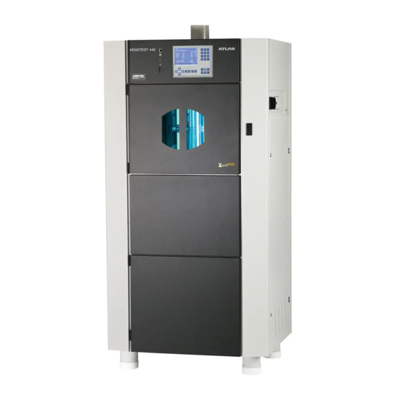
Operating Manual Xenotest ® Description of the instrument View from the front and right Fig. 3: View from the front: View from the right: 1 Control panel with display 7 Air inlet for the lamp cooling 2 Test chamber and radiation panel 8 Door to the electrical supply system 3 Sample rack with sample rack holder 9 Door catch for the test chamber... -
Page 16: View From The Rear, Left And Above
Operating Manual Xenotest ® Description of the instrument View from the rear, left and above Fig. 4: View from the rear: View from the left: 1 Instrument rear panel 7 Air inlet for test chamber cooling 2 Air outlet for test chamber cooling 3 Cover panel for simple access to View from above: the inside of the device... -
Page 17: View Of Test Chamber
Operating Manual Xenotest ® Description of the instrument View of test chamber Fig. 5: 1 Xenon lamps for radiating material samples 2 Sample rack for holding the sample 3 Integrated sensor for measuring the test chamber temperature and the relative humidity in the test chamber 4 Air shaft for air supply to the test chamber 5 Sample rack for revolving the samples around the xenon lamps 6 Receptacle for sample rack... - Page 18 Operating Manual Xenotest ® Description of the instrument View of Xenotest 440 control panel Fig. 6 ® Fig. 6: 1 Display that shows the menu dialogs, status displays and program parameters Please select test 2 Arrow keys for navigation in the menus 3 Numeric keypad for entering the program parameters Test 1 User defined test...
-
Page 19: Functional Description
Fig. 7 ® Fig. 7: The Xenotest 440 is turned on with the main switch 3 and then operated by the keypad on the program control panel 2 . The microprocessor-aided program control enables both opening of already pre-programmed test sequences and the design and initialization of user- specific tests. -
Page 20: Optical Filter Systems
Operating Manual Xenotest ® Functional description Optical filter systems Fig. 8 NOTE – spectral power distribution Depending on the selected test method, the appropriate filter system which surrounds the xenon lamps 1 in order to create the prescribed/desired spectral energy distribution. -
Page 21: Spectral Power Distribution
Operating Manual Xenotest ® Functional description Spectral power distribution 5.4.1 Overview of optical filter systems Table 1 Optical filters Outer cylinder TM16 filter, 6 pieces Special UV glass filter XENOCHROME 320, 11 pieces Special UV glass filter ® Daylight B04, 11 pieces Special UV glass filter Inhalt/Content/Sommaire - 21 -... -
Page 22: Spectral Power Distribution Tm16
Operating Manual Xenotest ® Functional description 5.4.2 Spectral power distribution TM16 Fig. 10: The diagram shows the spectral power distribution in the wavelength range of 300 nm – 800 nm of the TM16 filter system in comparison with the specification of AATCC TM16. Fig. -
Page 23: Spectral Power Distribution Daylight B04 Filter System
Operating Manual Xenotest ® Functional description 5.4.4 Spectral power distribution daylight B04 filter system Fig. 12: The diagram represents the spectral energy distribution in the wavelength range from 300 nm to 800 nm using filter system daylight B04 in comparison with CIE 85 (table 4). Fig. -
Page 24: Radiation System
Operating Manual Xenotest ® Functional description Radiation System Fig. 13: The samples rotate on the sample rack 1 around the xenon lamps and the filter system.The irradiance is controlled by the XENOSENSIV RC sensor 2 . ® Fig. 13 Inhalt/Content/Sommaire - 24 -... -
Page 25: Ventilation System
Operating Manual Xenotest ® Functional description Ventilation system Fig. 14 The Xenotest 440 is an air-cooled instrument. The cool- ® ing system uses two different air sources. • Air flow system for the lamp cooling • Air flow system for the test chamber cooling 5.6.1 Lamp cooling Fig. -
Page 26: Humidity Function
Operating Manual Xenotest ® Functional description Humidity function Fig. 16 The humidity function of the Xenotest 440 enables sam- ples to be tested under controlled humidity conditions. • The humidification of the test chamber is generated by an aerosol-free ultrasonic humidifier. -
Page 27: Sample Spraying
Operating Manual Xenotest ® Functional description Sample spraying Fig. 17 The sample spraying of the Xenotest 440 enables ® spraying of the samples with the processed water during a wet cycle. Fig. 17: The humidifier as well as the sample spraying are fed from a water tank 1 inside the instrument. -
Page 28: Measuring And Control Sensors
Operating Manual Xenotest ® Functional description Measuring and control sensors Fig. 18 Fig. 18: A combined temperature and humidity sensor 1 is in- stalled in the test chamber of the Xenotest 440. ® The test chamber temperature and relative humidity are measured and regulated with this sensor. -
Page 29: Start Up
The instrument may only be started for the first time by Touching live parts can lead to life threat- an Atlas technical service or authorized service repre- ening electrical shock. Disconnect the in- sentative. All the functioning components of the instru- strument from the power supply before ment are checked during first-time start up. -
Page 30: Installing / Removing The Xenon Lamps
Operating Manual Xenotest ® Start up Installing / removing the xenon lamps Fig. 19 NOTE – warranty complaint lamp set In the event of a warranty claim, both lamps must be sent back together with the appropriate warranty card and the lamp file. Only then can a claim be made under the warranty! The lamp file of the used lamps can be saved on an SD card under “Save settings/device/lamp age/lamp file.”... -
Page 31: Removing The Xenon Lamps
Operating Manual Xenotest ® Start up 6.3.1 Removing the xenon lamps Fig. 20 Fig. 19 (page 30): 1. Remove the exhaust air channel adapter 1 or the technical ventilation system. 2. Lift up the exhaust air cover with connection nozzle 4 . 3. -
Page 32: Setting The Replacement Schedule For The Lamps
Negative effects on the results obtained with these expired lamps cannot be ruled out. Therefore, use of the lamps beyond the useful life specified by Atlas is at your own risk. Inhalt/Content/Sommaire - 32 -... - Page 33 Operating Manual Xenotest ® Start up Changing optical filters Fig. 21 Inserting optical filters (fig. 21) XENOCHROME 320 / B04: ® 1. Clean the filter discs with a dry, soft cloth. 2. Insert the filter discs 1 into the opening 3 of the filter assembly 2 from above.
-
Page 34: Loading The Sample Rack
Operating Manual Xenotest ® Start up Loading the sample rack Fig. 23 The sample racks are an optional accessory and can be ordered separately depending on the application. NOTE – loading the sample rack All sample holders must always be inserted into the sample rack to guarantee reproducible test conditions. -
Page 35: Operating Manual Xenotest
Operating Manual Xenotest ® Start up 6.5.2 Special sample rack (fig. 25) Fig. 25 The special sample rack 2 (ID no. 56079777) with di- mensions 320 mm × 48 mm can be equipped with two samples 135 × 45 mm with a thickness of up to approx. 10 mm. - Page 36 Operating Manual Xenotest ® Start up 6.5.3 Special sample rack 1B (fig. 26) Fig. 26 The special sample rack 1B (ID no. 56080037) with dimensions 320 mm × 80 mm can be equipped with samples with a thickness of up to approx. 10 mm. The sample rack plate 4 fixes the samples.
- Page 37 Operating Manual Xenotest ® Start up 6.5.4 Special sample rack 2B (fig. 28) Fig. 28 The special sample rack 2B is suitable for technical tex- tiles or plastics, or other materials which are subjected to mechanical tension tests after your light or weather resistance tests.
-
Page 38: General
Operating Manual Xenotest ® Start up XENOSENSIV Fig. 30 ® 6.6.1 General The XENOSENIV RC sends the measured data to the instrument by a wireless connection. The instrument must be equipped with an appropriate receiver. The sensor is available in the following versions: XENOSENSIV RC-34 BST XENOSENSIV RC-420 BPT 6.6.2... -
Page 39: Power Supply
This helps avoid extended periods of downtime. Original spare batteries can be ordered from Atlas (ID No. 56055009). Please observe the instructions for disposal of the battery. NOTE – battery voltage If the battery voltage is too low, the test is interrupted. -
Page 40: Disposal Of The Battery
2. Insert the sensor holder (with mounted XENOSEN- authorities. SIV RC) into the sample rack. • They can also give old batteries to the Atlas service technician who will then pass them on for proper dis- posal. Fig. 32 •... -
Page 41: Filling The Water Tank
Fig. 34: 1. Place the adapter 1 of the customer’s exhaust air system on the connection nozzle on Xenotest 440. The connection nozzle has a diameter of 100 mm. 2. Check whether the exhaust air system has an open output outdoors or the on-site technical ventilation system is ready for operation. -
Page 42: Interfaces
Operating Manual Xenotest ® Start up Interfaces Fig. 35 Fig. 35: The Xenotest ® 440 instrument is equipped with four in- terfaces for exchanging data with external systems. Network connection 1 : The test instrument can be integrated into a network via the Ethernet port (see Software Documentation sect. -
Page 43: Incoming Power Connection
Operating Manual Xenotest ® Start up 6.10 Incoming power connection Fig. 36 WARNING – electrical shock! Touching live parts can lead to life threat- ening electrical shock. Check plugs and power cables for damage before connect- ing to the incoming power. Damaged parts should not be used for electrical connec- tion! The Xenotest... -
Page 44: Operation
Operating Manual Xenotest ® Operation Operating the keypad/touch-screen Fig. 37 Operation/programming of Xenotest ® Fig. 37: Please select test The device controller is operated on the touch screen Test 1 User defined test either with a finger or a stylus: Test 2 Standards 2 Function keys for activating the basic functions and... -
Page 45: Turning On The Instrument
Operating Manual Xenotest ® Operation Operating the keypad/touch-screen Fig. 38 Basic functions Fig. 38: Please enter your user name Function keys 2 for controlling the basic functions: confirm entry cancel action or return to respective previously selected menu Ü... -
Page 46: Setting The Test Chamber Humidity
Operating Manual Xenotest ® Operation Setting the test chamber humidity Fig. 40 The desired humidity in the test chamber is entered as a parameter on the instrument control panel. The maxi- mum humidity which can actually be achieved in the test chamber depends on the ambient conditions. -
Page 47: Settings For Test Programs
Operating Manual Xenotest ® Operation Settings for test programs The program controller of the Xenotest 440 enables ® programming of ten test programs in addition to the pre- programmed tests. The parameter input is menu guided by the touch screen of the device controller. NOTE –... -
Page 48: Calibration And Adjustment
Calibration of the XENOSENSIV RC Sensor If the new factor is outside the range of 0.8 to 1.2, the XENOSENSIV RC should be sent to Atlas for inspection. The irradiance and the surface temperature can be checked (calibrated) with a XenoCal during a running 3. -
Page 49: Note On Implementation
Operating Manual Xenotest ® Operation Note on implementation When working according to quality management prin- ciples, a validation of the integration (implementation) of the test instrument into the existing processes usually takes place first. It is recommended to carry out a user validation process with typical test materials for the selected test method. -
Page 50: Shut Down
Operating Manual Xenotest ® Shut down Turning off the instrument Removing samples The instrument can be turned off at the end of or inter- CAUTION – danger of burns! ruption of a test program. The samples heat up considerably during a test program run. -
Page 51: Decommissioning Of Instrument
Shut down Decommissioning of instrument Disposal of the instrument in EU countries out- Atlas instruments are classified according to the EU side the Federal Republic of Germany: directive 2012/19/EU of the European Parliament and Commission on Waste Electrical and Electronic Equip- ment as “monitoring and control instruments for exclu-... -
Page 52: Troubleshooting
Operating Manual Xenotest ® Troubleshooting Error messages and troubleshooting A list of all the error messages and the necessary trou- bleshooting can be found in the Xenotest ® 440 software documentation manual. Inhalt/Content/Sommaire - 52 -... -
Page 53: Maintenance
The instrument must be inspected annually. The scope Repair work may only be carried out by appropriately of the inspection includes: trained and qualified personnel or by an Atlas Technical • Checking the protective components of the instru- Service Representative. Only original spare parts should ment be used to install or change instrument components. -
Page 54: Maintenance
Operating Manual Xenotest ® Maintenance 10.3 Maintenance Fig. 43 WARNING – electrical shock! Touching live parts can lead to life threat- ening electrical shock. Disconnect the in- strument from the power supply before be- ginning maintenance work! • Turn off the instrument at the main ON/OFF switch •... - Page 55 Operating Manual Xenotest ® Maintenance 10.3 Maintenance Fig. 45 Changing the xenon lamps To maintain constant radiation, it is necessary to replace the xenon lamps only in pairs (see sect. 5.2. and sect. 6.3). The recommended change is indicated on the pro- gram control panel.
-
Page 56: Cleaning
Operating Manual Xenotest ® Maintenance 10.4 Cleaning Cleaning the filters and outer cylinders Cleaning step 1: with deionized water and citric acid. Removes acid soluble residue. Cleaning step 2: deionized water. Removes polar residues incl. residues from step 1. Cleaning step 3: Ethanol absolute. Removes organic residues. -
Page 57: Consumable Parts
The safety and reliability of the instrument is only guaranteed if the defined consumable parts listed below are used. The use of other parts may hold hidden risks and is prohibited. Table 2 Here you can find the consumable parts recommended by Atlas which can be changed by the user. Item Designation Change to Life ID No. -
Page 58: Technical Data
Operating Manual Xenotest ® Technical Data Technical Data Interfaces: Incoming power: RS232 Incoming power connection: 3P/N/PE Memory chip CEE (32A,5-pol.,6h) Ethernet Nominal voltage: 400V ±10% Nominal frequency: 50/60 Hz Data recording: Rated curr: max. 28 A RS232 Nominal power: max. 8 kVA Memory chip Nominal power of xenon lamps: 2200 VA... -
Page 59: Accessories
Operating Manual Xenotest ® Accessories Accessories Order no.: Designation 56079772 Application kit 105-B02 (non-aging) Included in delivery: * XENOCHROME 320 filter system (non-aging) ® * Sample rack set for samples with a thickness of up to 3 mm (19 pieces) * Set of masks 9, 18 and 27 mm aperture width (38 pieces each) * ISO blue wool scale and ISO grey scale * Sample rack cards (130 pieces) -
Page 60: Ec Declaration Of Conformity
Vogelsbergstraße 22 63589 Linsengericht Germany hereby declares, that the machine designated below Machine model: Xenotest 440 Designation: Light exposure and weathering testing equipment Conforms with the requirements of the following regulation: EU Machine Directive 2006/42/EG In addition, the machine conforms with the requirements of the following regulation:... -
Page 61: Notes
Operating Manual Xenotest ® Notes Notes Inhalt/Content/Sommaire - 61 -... - Page 62 Operating Manual Xenotest ® Notes Notes Inhalt/Content/Sommaire - 62 -...
- Page 63 Operating Manual Xenotest ® Notes Notes Inhalt/Content/Sommaire - 63 -...
- Page 64 Operating Manual Xenotest ® Atlas Material Testing Technology GmbH Vogelsbergstr. 22 63589 Linsengericht / Germany (p): + 49-6051-707-140 (f): + 49-6051-707-149 email: atlas.info@ametek.de www.atlas-mts.com Id.-Nr.: 56352711 01/14 Inhalt/Content/Sommaire...
Need help?
Do you have a question about the Xenotest 440 and is the answer not in the manual?
Questions and answers