Advertisement
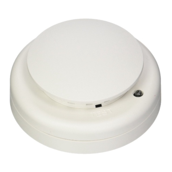
ESL 700 Series Conventional Smoke and Heat
Detector Installation Sheet
Description
The ESL 700 Series smoke or smoke with rate-of-rise heat
detectors have field-replaceable optical chambers. The
detector uses an optical sensing chamber to detect smoke and
a fixed-temperature heat sensor to detect heat from fire. For a
list of model numbers, see Table 1. For a list of accessories,
see Table 2.
Table 1: Model numbers
Number
Description
Head (sold separately from base)
711U
Two-wire photoelectric smoke detector head
713-5U
Two-wire rate-of-rise and 57°C (135°F) fixed
temperature heat detector head
721U
Two-wire photoelectric smoke detector, with remote test
input and remote alarm/trouble LED output
721UT
Two-wire photoelectric, with rate-of-rise heat detector
head with remote test, alarm/trouble LED output
731U [1]
Two-wire photoelectric smoke detector head with
auxiliary relay (NC/NO) output
741U
Four-wire photoelectric smoke detector with alarm relay
(NO) output and remote alarm/trouble LED output
741UT
Four-wire photoelectric smoke and rate-of-rise heat
detector head, alarm relay (NO) output and remote
alarm/trouble LED output
731L
(OEM only, not for resale) see 731U description
Base (sold separately from head)
701U
Three-terminal base for 711U and 713-5U heads, 6 in.
(15 cm) base, connectors
© 2014 UTC Fire & Security Americas Corporation, Inc.
Number
Description
Six-terminal base for all heads; 4 in. (10 cm)
702E-
10PKG
702U
Six-terminal base for all heads, 6 in. (15 cm)
702RE
Six-terminal base for 731U, 4 in. (10 cm)
702RU
Six-terminal base for 731U, 6 in. (15 cm)
Head with base (sold together)
TS7-4
Four-wire photoelectric smoke detector with alarm relay
(NO) output and remote alarm/trouble LED output
[1] UL Listed for releasing devices such as electromagnetic door
holders, fire dampers, or smoke dampers.
High voltage (120 V) base and head
The 702RE and 702RU bases have a special plastic protrusion
built in to prevent insertion of a low-voltage detector head into
a base containing damaging high voltages (120 V). These
bases can only be used with 731U heads. The 731U includes
auxiliary relay contacts and is only required when connecting
high voltage to the auxiliary relay.
Note:
The 731U heads can also be used with 702E and 702U
bases for low voltage applications.
Table 2: Accessories
Number
Description
204-12/24V
End-of-line, power supervision relay for four-wire
applications
211-10PKG
Replaceable optical chamber for ESL smoke
detectors (set of 10)
706U1A [1]
Remote indicator with red alarm LED, for use with
721U and 741UT
706U2A [1][2]
Remote indicator with red alarm LED and keyed
remote test, for use with 721U and 721UT
706U3A [1][2]
Remote indicator with red alarm LED, keyed
remote test and reset, for use with 721U and
741UT
SM-200
Smoke! In A Can (canned smoke) for functional
testing of smoke detectors
SM-EXT1
Extension tube for Smoke! In A Can
[1] The remote alarm/trouble LED on the 706U1A, 706U2A, and
706U3A models works with both two-wire 721U/721UT and four-wire
741U/741UT models when connected as shown in Figure 6 item 7 and
Figure 7 item 11.
[2] 706U2A and 706U3A only work with the 721U/721UT two-wire
models, when connected as shown in Figure 6 item 6.
1 / 6
P/N 13083-EN • REV J • ISS 10APR14
Advertisement
Table of Contents

Related Manuals for ESL 700 Series


Summary of Contents for ESL 700 Series
- Page 1 (120 V). These The ESL 700 Series smoke or smoke with rate-of-rise heat bases can only be used with 731U heads. The 731U includes detectors have field-replaceable optical chambers.
-
Page 2: Installation
Installation Figure 1: Smoke detector placement Notes • Locate detectors in an operating environment as defined in “Specifications” on page 6. • Mount detectors on a firm, permanent surface. Placement and spacing Use the following location guidelines to optimize performance and reduce the chance of false alarms. - Page 3 To install the base: Removing the detector head Remove the base cover by simply twisting it counter- To remove the detector head, turn it counterclockwise. If the clockwise to unsnap (see Figure 2). locking tab was removed, insert a small screwdriver into the locking tab slot on the side of the base, and then press in while Pull the field wires through the electrical box, and then simultaneously turning the detector head counterclockwise...
- Page 4 Figure 6: 700 series two-wire wiring diagram IDC_IN IDC_IN (10) 702RU, 702RE, 701U 702U, 702E 702U, or 702E Figure 7: 700 series four-wire wiring diagram (741UT head) PWR_IN PWR_IN 702U, 702E 702U, 702E IDC_IN IDC_IN (11) (1) Initiating device circuit from a compatible listed control panel...
- Page 5 Figure 8: Continuity switch Table 3: Description of LED flashes 0 to 1 Indication: Unserviceable hardware fault. Action: Reset and rerun the sensitivity test. If the error persists, replace the unit. 2 to 3 Indication: Unit is becoming insensitive. Action: Clean and reset the unit. Rerun the sensitivity test. If the error persists, replace the unit.
-
Page 6: Maintenance
Maintenance Typical alarm current Two-wire: 60 mA (max.), if not limited by control panel If a smoke detector drifts beyond its approved sensitivity range Four-wire: 50 mA (max.) but 15 mA (min.) for more than 24 hours, or fails internal diagnostic tests during Remote LED output 5.0 to 8.5 mA power-up, the unit automatically indicates trouble by flashing...
Need help?
Do you have a question about the 700 Series and is the answer not in the manual?
Questions and answers