Advertisement
Quick Links
Building instructions
Congratulations, you have chosen a quality product MADE IN GERMANY.
Please read these instructions carefully before beginning construction and then proceed
with the step by step construction.
General information about the model:
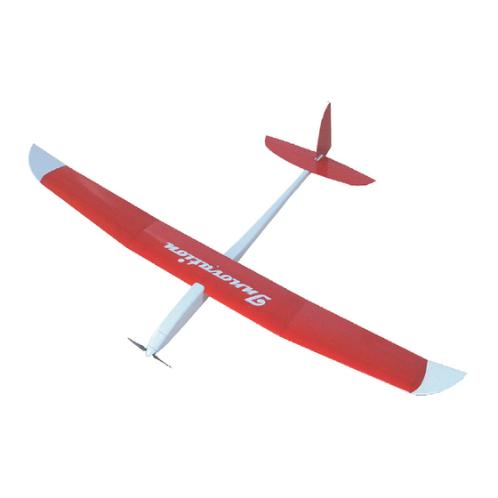
The INNOVATION is a small electric glider (or sailplane) with fully-sheeted wings.
Despite the low flying weight, the model can be flown even with some light winds.
The wing profile MB 971 is used and contributes to this models ability.
With conscientious structure, higher speeds can be achieved.
Tools and adhesives:
Modelling knife, small balsa plane, 100 and 320 grit sandpaper, a straight building board about 50 x 90 cm
Superglue, thin CA
and thick CA . UHU plus fast or 5 minute epoxy.
The corresponding pictograms are inserted in the individual construction sections for the adhesive notes.
White glue can also be used for wood joints. However, it is not as easy to sand and causes slightly higher
weight. The parts should all be allowed to fully cure and be secured with needles or weights.
Construction:
The temperature and humidity of the plan can lead to dimensional differences to the components.
The adhesives given in this manual are only suggestions.
For large-area gluing, a thick liquid adhesive is suitable. To do this apply the adhesive to the component and
then "float" and align. Do not worry, the component can still be moved.
Now press the component at a corner, check, press on the opposite corner as well.
If everything fits, press the entire component.
The side panels are reinforced in the required areas by doublers made of balsa or plywood.
The ribs and the spar web are pre-cut.
The wings are built in three parts and are fully sheeted.
Due to the low profile thickness, tie bars are used.
The spar web and the ribs are inserted into the lower sheeting for a simple construction.
To sand the airfoil, profiled templates are attached for the important leading edge.
The wings of our test models were covered with ORACOVER.
The rudder deflections given in this manual are a basic setting for the first flights.
These can easily be adapted to your style of flying.
ENJOY your Innovation!
Advertisement

Summary of Contents for Hoellein Innovation
-
Page 1: Building Instructions
General information about the model: The INNOVATION is a small electric glider (or sailplane) with fully-sheeted wings. Despite the low flying weight, the model can be flown even with some light winds. The wing profile MB 971 is used and contributes to this models ability. - Page 2 • Cover the blueprint with saran wrap (clear plastic). • Glue the lower sheeting for the center panel, part F1 and F2 together. • Glue together the upper sheeting for the center panel, part F3 and F4 together. • Glue the lower sheeting for the outside panels F5 and F6 together. •...
- Page 3 • Glue the web spar for the center panel, part F9 to the lower sheeting F1 / F2. • Glue the web spars F10 for the outer surfaces of the lower panel F5 / F6. Caution: make sure that you make a left and a right...
- Page 4 • Insert and glue ribs F15 - F21 at the predetermined positions on the panels F5 / F6 and to the web spar F10. • Attach the connecting ribs F14 to the sheeting F5 / F6 and to the spar F10. Caution: The ribs F14 must sit against the angle of the spar F10.
- Page 5 • Glue the upper sheeting F3 / F4 to the center panel. Make sure to add glue on all ribs, the spar, the leading edge and the angled trailing edge of the lower sheeting. Position the upper sheeting and secure it with needles and weights. Caution: To get a flat and straight wing, the wing center section should be left until fully cured.
- Page 6 • Divide the edge strip F24 (triangular piece of balsa) in 2 even pieces. • Glue the edge curves F24 flush to the outer parts of the surfaces. • After the glue has cured, gently sand to match the airfoil. TIP: A sheet of paper or masking tape can be applied to the sheeting to protect it from damage during sanding.
- Page 7 • Glue a front side part R1 to the rear side part R2L. • Glue a front side part R1 to the rear side part R2R Note: The difference between the two sides is that the right side opening for the pushrod cable is wider than the left.
- Page 8 • Glue the R6 pieces and clamp them together. • Glue the parts R7 and R8 to each other and clamp until cured. • Glue the nut R9 with epoxy. Caution: Ensure no glue gets into the threads. • Verify the frames R6 and R11, servo frame R10 and the wing holder R7 / R8 that they all fit at right angles into the corresponding slots of the doubler R3 of the right fuselage.
- Page 9 • Screw the motor to the motor bulkhead R33 using the enclosed screws. Wrap the motor in paper/ or tape so that it fits snugly into the nosepiece. This will ensure that the motor is centered and that the motor will turn freely after gluing the bulkhead.
- Page 10 • Glue the bottom of the fuselage R15 to R20 starting from the end of the fuselage and secure with needles. Note: Make sure that the boom is straight. The last piece R15 must be trimmed to fit. • Feed the guide tubes R21 and check for smooth operation of the pushrod cables R22. If necessary, slightly enlarge the openings in the sides of the fuse using a 2mm drill bit.
- Page 11 • Place the R28 battery hatch doubler in the center, flush with the front and rear and glue to R27. • Glue the reinforcements R29 to the left and right to the doubler R28 and to R27. Caution: The square end of the reinforcement R29 must be flush with the side with the notch for the magnetic closure in doubler R28.
- Page 12 • Join together the connectors L1. • Glue the elevator L2 to the connector L1. • Sand all elevator parts L1, L2 and L3 as well as rudder parts L4 and L5 Sand and bevel according to the shaded cuts in the plan. Note: Make sure that the specified rudder deflections are achieved.
- Page 13 • Install the motor and the ESC. Note: To prevent the motor cable rubbing between the motor bell and the fuselage. Glue in a small piece of balsa over the wires to the fuselage doubler. • Install the servos (no screws yet). Set servo arms accordingly. •...
-
Page 14: Parts List
Aligning empennage and wings The opposite dimensions must be equal. Place battery accordingly to achieve a CG of 48mm behind the leading edge. The rudder deflections + 20mm The elevator deflections +/- 8mm. Flying Höhenruder auf Neutralstellung kontrollieren Akku etwas weiter nach vorne Test the model initially by throwing it into the wind. - Page 15 Description l a i Sheet No. Leading Edge 74.13 Wingtips 74.22 74.14 Wing joiner Plywood 74.18 Wing Anchor Plywood 74.18 Front fuselage side 74.10 & Rear fuselage side 74.11 Fuselage doubler Plywood 74.19 Lower boom doubler 74.17 Upper boom doubler 74.17 Plywood 74.18...
-
Page 16: Building Instructions
This English translated version is published with the expressed permission of GRÜNER CNC Service. Download the original document here with full illustrations. http://www.hoellein.com/downloads/pdf-artikel/gruener/innovation.pdf Grü n er can not be held liable for consequential damages that may arise during the operation of products from our product range.
Need help?
Do you have a question about the Innovation and is the answer not in the manual?
Questions and answers