Table of Contents
Advertisement
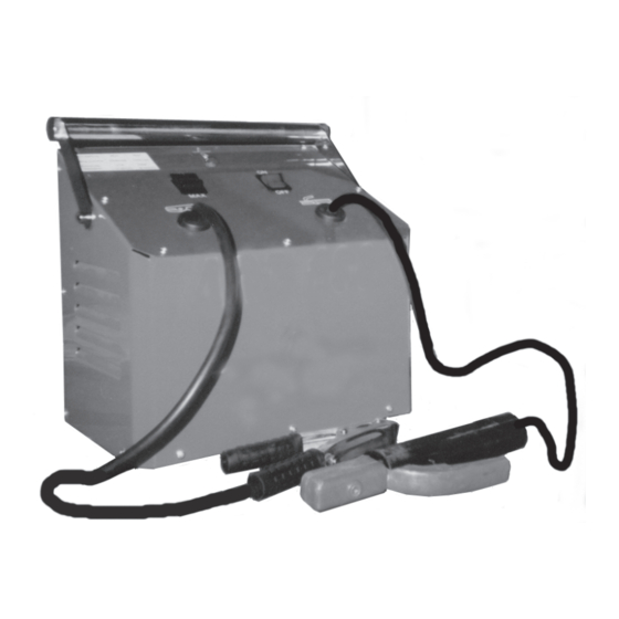
HOBBY ARC WELDER
Model 55594
ASSEMBLY AND OPERATING INSTRUCTIONS
®
3491 Mission Oaks Blvd., Camarillo, CA 93011
Visit our Web site at: http://www.harborfreight.com
TO PREVENT SERIOUS INJURY,
READ AND UNDERSTAND ALL WARNINGS
AND INSTRUCTIONS BEFORE USE.
©
Copyright 2005 by Harbor Freight Tools
®
. All rights reserved. No portion of this
manual or any artwork contained herein may be reproduced in any shape or form
without the express written consent of Harbor Freight Tools.
For technical questions, please call 1-800-444-3353.
REV 07d
Advertisement
Table of Contents

Related Manuals for Chicago Electric HOBBY ARC WELDER


Summary of Contents for Chicago Electric HOBBY ARC WELDER
- Page 1 HOBBY ARC WELDER Model 55594 ASSEMBLY AND OPERATING INSTRUCTIONS ® 3491 Mission Oaks Blvd., Camarillo, CA 93011 Visit our Web site at: http://www.harborfreight.com TO PREVENT SERIOUS INJURY, READ AND UNDERSTAND ALL WARNINGS AND INSTRUCTIONS BEFORE USE. © Copyright 2005 by Harbor Freight Tools ®...
-
Page 2: Product Specifications
PRODUCT SPECIFICATIONS ) t i - t l c t i y t i " 4 y t i " 6 " 4 l l a " 4 " 4 " 8 SAVE THIS MANUAL You will need this manual for the safety warnings and precautions, assembly, operating, inspection, maintenance and cleaning procedures, parts list and assembly diagram. -
Page 3: Electrical Safety
sparks which may ignite the dust or fumes. Keep bystanders, children, and visitors away while operating welding equip- ment. Distractions can cause you to lose control. Protect others in the work area from arc rays, sparks, and slag. Provide barriers or shields as needed. ELECTRICAL SAFETY Grounded welding equipment must be plugged into an outlet properly installed and grounded in accordance with all codes and ordinances. - Page 4 Dress properly. Do not wear loose clothing or jewelry. Contain long hair. Keep your hair, clothing, and gloves away from hot or moving parts. Loose clothes, jewelry, or long hair can be caught in hot or moving parts. (See page 5, number 3, for recommended safety clothing.) Avoid accidental starting.
-
Page 5: Specific Safety Rules
Maintain welding equipment with care. Keep equipment clean and dry. Properly maintained equipment is less likely to malfunction and is easier to control. Do not use damaged welding equipment. Tag damaged equipment “Do not use” until repaired. Check for misalignment or binding of moving parts, breakage of parts, and any other condition that may affect the equipment’s operation. - Page 6 to protect head and neck. Use aprons, cape, sleeves and shoulder covers, and bibs designed and approved for welding procedures. When welding overhead or in confined spaces, wear flame resistant ear plugs or ear muffs to keep sparks out of ears. Avoid overexposure to fumes and gases.
- Page 7 materials. If relocation is not possible, protect the combustibles with a cover made of fire resistant material. Remove or make safe all combustible materials for a radius of 35 feet (10 meters) around the work area. Use a fire resistant material to cover or block all open doorways, windows, cracks, and other openings.
- Page 8 Do not touch the welding wire if you are in contact with the workpiece, ground, or another welding wire from a different machine. Do not allow the welding wire to touch earth ground. Accidental earth discharges may cause overheating and fire hazards. Do not pass equipment cables through or near lifting chains, crane cables, or any electrical lines.
-
Page 9: Grounded Tools: Tools With Three Prong Plugs
WARNING! This product, when used for welding, cutting, and similar applications, produces chemicals known to the State of California to cause cancer and birth defects (or other reproductive harm). (California Health & Safety code 25249.5, et seq.) WARNING! People with pacemakers should consult with their physician(s) before using this product. -
Page 10: Double Insulated Tools: Tools With Two Prong Plugs
must be the only wire connected to the equipment’s grounding system and must never be attached to an electrically “live” terminal. (See Figure A.) Your welding equipment must be plugged into an appropriate outlet, properly installed and grounded in accordance with all codes and ordinances. The plug and outlet should look like those in the following illustration. -
Page 11: Extension Cords
EXTENSION CORDS Grounded welding equipment requires a three wire extension cord. Double Insulated welding equipment can use either a two or three wire extension cord. As the distance from the supply outlet increases, you must use a heavier gauge extension cord. Using extension cords with inadequately sized wire causes a serious drop in voltage, resulting in loss of power and possible tool damage. -
Page 12: Welder Controls
SYMBOLOGY Double Insulated Canadian Standards Association Underwriters Laboratories, Inc. Volts Alternating Current Amperes No Load Revolutions FIGURE D xxxx/min. per Minute (RPM) WELDER CONTROLS NOTE: For additional information regarding the parts listed in the following pages, refer to the Assembly Diagram on page 21. TOP VIEW - WELDER THERMAL PROTECTION... -
Page 13: Assembly Instructions
ASSEMBLY INSTRUCTIONS CAUTION! Always make sure the Power Cord of the Welder is unplugged from the electrical outlet prior to assembly or making any adjustments to the tool. CAUTION! Always wear heavy duty work gloves for Ground Clamp and Electrode Holder Assembly. To Attach The Ground Clamp: WARNING! Make sure to connect the Ground Clamp (28) to the Ground Cable only. - Page 14 To Attach The Electrode Handle: WARNING! Make sure to connect the Electrode Holder (27) to the Electrode Cable only. (See Figures E and G.) Slide the Handle Grip off the Electrode Holder (27). (See Figure G.) Insert the Electrode Cable through the Handle Grip. (See Figure G.) Place the bare end of the Electrode Cable into the open end of the Electrode Holder (27).
-
Page 15: Operating Instructions
To Assemble The Face Shield: Slide the Lens downward into the inside opening of the Face Shield (26). (See Figure H.) Slide the Lens Holder Brackets downward into the inside opening of the Face Shield (26). (See Figure H.) Snap the Face Shield Handle into the lower opening in the Face Shield (26). (See Figure H.) LENS LENS HOLDER... - Page 16 amperage or voltage, or duty cycle, before welding. This Welder, at its 10% at 55 AMPs duty cycle (low), can run continuously under load for 1 minute out of each 10 minute period. After using continuously for one minute, the Welder must sit unused for 9 minutes. At its 6% at 70 AMPs duty cycle (high), the Welder can run continuously under load for 36 seconds out of each 10 minute period.
- Page 17 Insert the bare end of an AC Electrode (not included) securely in the Electrode Holder (27). (See Figure I.) While holding the Electrode Holder (27) with its Electrode clearly out of the way of any grounded objects, turn the Power Switch ON/OFF (9A) to its “ON” position.
- Page 18 EXAMPLE OF A PROPER WELD Typically, three factors which most affect the quality of a weld are as follows: (A) The speed at which you advance along the weld. (B) The length of arc. (C) The rate of amperes at which you are welding. Adjusting one or more of these three factors can help increase the quality of weld.
-
Page 19: Troubleshooting
TROUBLESHOOTING Symptom Probable Cause Suggested Solution Welder does not operate 1. Improper fuse or circuit 1. Replace fuse, reset Or continually blows fuses. breaker. breaker, or use delayed action breaker. 2. Fuse blown or circuit breaker 2. Replace fuse or reset tripped. -
Page 20: Please Read The Following Carefully
When storing, make sure to store the Welder in a safe, clean, dry location out of reach of children and unauthorized people. CAUTION! All maintenance, service, and repairs not listed in this manual are only to be attempted by a qualified service technician. PLEASE READ THE FOLLOWING CAREFULLY THE MANUFACTURER AND/OR DISTRIBUTOR HAS PROVIDED THE PARTS LIST AND ASSEMBLY DIAGRAM IN THIS MANUAL AS A REFERENCE TOOL ONLY. -
Page 21: Assembly Diagram
ASSEMBLY DIAGRAM 26: FACE SHIELD NOT SHOWN. 27: ELECTRODE HOLDER NOT SHOWN. 28: GROUND CLAMP NOT SHOWN. 3 4 5 22, 24, 25 22, 23 21, 22 17, 18, 19 NOTE: Some parts are listed and shown for illustration purposes only, and are not available individually as replacement parts. -
Page 22: Electrical Schematic
ELECTRICAL SCHEMATIC SKU 55594 For technical questions, please call 1-800-444-3353. Page 22...
Need help?
Do you have a question about the HOBBY ARC WELDER and is the answer not in the manual?
Questions and answers