Table of Contents
Advertisement
Advertisement
Table of Contents

Related Manuals for TRENDnet TEG-S80ES


Summary of Contents for TRENDnet TEG-S80ES
- Page 1 Cover Page TRENDnet User’s Guide...
-
Page 2: Table Of Contents
Set Ingress Rate Limiting..................30 Community Table Settings ................. 14 Set Egress Rate Limiting ..................31 Host Settings ...................... 15 VLAN ..........................32 Statistics ........................16 Add, modify, and remove VLANs ............... 32 © Copyright 2018 TRENDnet. All Rights Reserved. - Page 3 Upgrade your switch firmware ................45 Configuration ....................... 46 Backup and Restore your switches configuration setting........46 Diagnostics ........................47 Cable Diagnostics Test ..................47 Reboot ......................... 48 Reboot/Reset to Factory Defaults ..............48 © Copyright 2018 TRENDnet. All Rights Reserved.
-
Page 4: Product Overview
The web-based management interface offers features for traffic control, RSTP, VLAN, QoS, access control, static link aggregation, and monitoring. TRENDnet’s TEG-S80ES allows for simple network integration into your SMB network. EdgeSmart Management... -
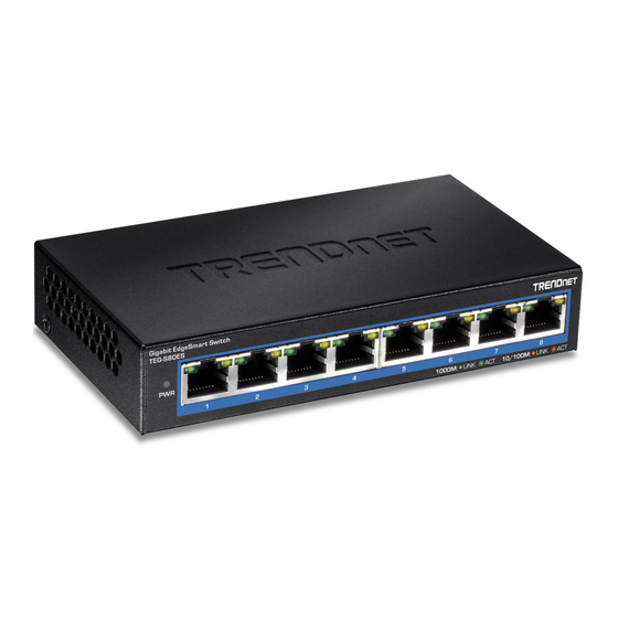
Page 5: Product Hardware Features
Network speed at 1000 Mbps Left LED BLINKING Data is transmitting/receiving. (Green) Ethernet port is not connected. Ports 1-8 Network speed at 10/100 Mbps Right LED BLINKING Data is transmitting/receiving. (Amber) Ethernet port is not connected. © Copyright 2018 TRENDnet. All Rights Reserved. -
Page 6: Switch Installation
192.168.10.x (e.g. 192.168.10.25) and a subnet mask of 255.255.255.0. 4. Open your web browser, and type the IP address of the switch in the address bar, and then press Enter. The default IP address is 192.168.10.200. © Copyright 2018 TRENDnet. All Rights Reserved. - Page 7 NOTE: The configured settings are only applied to the switch’s temporary memory and will be lost upon the next power-cycle. Please follow these next steps to save the configurations to the switch’s NV-RAM to ensure the settings will remain throughout power-cycles and reboots: © Copyright 2018 TRENDnet. All Rights Reserved.
- Page 8 TRENDnet User’s Guide 1. From the menu on the left: click on Save, then click the blue button Save Settings to Flash. 2. Click Continue to return to the Web Configuration of your switch. © Copyright 2018 TRENDnet. All Rights Reserved.
-
Page 9: Connect Additional Devices To Your Switch
Note: If you encounter issues connecting to your network, there may be a problem with your computer or device network settings. Please ensure that your computer or device network settings (also called TCP/IP settings) are configured properly within the network subnet your switch is connected. © Copyright 2018 TRENDnet. All Rights Reserved. -
Page 10: Accessing Switch Management Interfaces
System Location - Displays the identifying system location of your switch. This information can be modified under the System section. System Contact – Displays the identifying system contact or system administrator of your switch. This information can be modified under the System section. © Copyright 2018 TRENDnet. All Rights Reserved. - Page 11 Default Gateway – Displays the current gateway address assigned to your switch. Automatic Network Features IPv4 DHCP Client Mode: Displays if your switch IPv4 address setting is set to DHCP client. © Copyright 2018 TRENDnet. All Rights Reserved.
-
Page 12: System
30 characters. System Contact - Specifies the name of the network administrator responsible for managing the switch. This contact name is optional and may contain up to 30 characters. 4. Click Apply. © Copyright 2018 TRENDnet. All Rights Reserved. -
Page 13: Ipv4 Settings
System IP Mode: Click the drop-down list and select Static to manually specify your IP address settings or DHCP to allow your switch to obtain IP address settings automatically from a DHCP server on your network. © Copyright 2018 TRENDnet. All Rights Reserved. -
Page 14: Administration
NOTE: The configured settings are only applied to the switch’s temporary memory and will be lost upon the next power-cycle. Please follow these next steps to save the configurations to the switch’s NV-RAM to ensure the settings will remain throughout power-cycles and reboots: © Copyright 2018 TRENDnet. All Rights Reserved. -
Page 15: Timeout
NV-RAM to ensure the settings will remain throughout power-cycles and reboots: 1. From the menu on the left: click on Save, then click the blue button Save Settings to Flash. © Copyright 2018 TRENDnet. All Rights Reserved. -
Page 16: Snmp
NOTE: The configured settings are only applied to the switch’s temporary memory and will be lost upon the next power-cycle. Please follow these next steps to save the configurations to the switch’s NV-RAM to ensure the settings will remain throughout power-cycles and reboots: © Copyright 2018 TRENDnet. All Rights Reserved. -
Page 17: Community Table Settings
SNMP User and Group Name on the SNMP User/Group page and then define a Community Name on the SNMP Community Table page. 1. Log into your switch management page (see “Access your switch management page” on page 7). © Copyright 2018 TRENDnet. All Rights Reserved. -
Page 18: Host Settings
Table page. If you enter a Community String that has not been pre-defined, the Trap Host entry is displayed, but agent/manager communication fails. Click Apply. The new host is added to the table. © Copyright 2018 TRENDnet. All Rights Reserved. -
Page 19: View Statistics
RxErr: Receive Error, number of frames that were failed to be received by the switch through the specified port number. Clear: Clicking Apply will clear the Statistic Information of that row (port number). Refresh: Clicking Refresh will refresh the data on the page. © Copyright 2018 TRENDnet. All Rights Reserved. -
Page 20: Ieee 802.3Az Eee
NV-RAM to ensure the settings will remain throughout power-cycles and reboots: 1. From the menu on the left: click on Save, then click the blue button Save Settings to Flash. © Copyright 2018 TRENDnet. All Rights Reserved. -
Page 21: Network
You can also disable an disable Auto-Negotiation on the port and set the port’s speed and unused port to secure it from unauthorized connections. The possible values duplex mode manually. are: © Copyright 2018 TRENDnet. All Rights Reserved. - Page 22 Disabled -This parameter indicates the switch is not permitted to accept jumbo frames. Note: When QoS is enabled, the Jumbo frame parameter cannot be enabled. 2. Click Continue to return to the Web Configuration of your switch. © Copyright 2018 TRENDnet. All Rights Reserved.
-
Page 23: Spanning Tree
STP Traps: You may set conditional triggers for automatically exporting logs upon: STP New Root Trap – Triggers when a new STP root is created. STP Topology Change Trap – Triggers when any change in the topology of the STP is detected. © Copyright 2018 TRENDnet. All Rights Reserved. -
Page 24: Configure Spanning Tree Protocol Port Settings
Network > Spanning Tree > RSTP Port Settings 1. Log into your switch management page (see “Access your switch management page” on page 7). 2. Click on Network, click on Spanning Tree, and click on RSTP Port Settings. © Copyright 2018 TRENDnet. All Rights Reserved. -
Page 25: Trunk
Link Aggregation Global Settings: To enable Trunking/Link Aggregation, select Enable. Otherwise, trunk settings with remain in its default state (Disabled). For each Trunk ID/Group, check the port numbers to add for each trunk group. © Copyright 2018 TRENDnet. All Rights Reserved. -
Page 26: Mirroring
To copy data transmitted on specific port, select Egress as the Frame Type and check the port number(s) under the section or you could click All to copy data received on all ports. © Copyright 2018 TRENDnet. All Rights Reserved. -
Page 27: Loopback Detection
Recover Time – Defines the time period when connectivity will be restored to a port where a loop was previously detected and blocked. Click Apply to save changes. 2. Click Continue to return to the Web Configuration of your switch. © Copyright 2018 TRENDnet. All Rights Reserved. - Page 28 NOTE: The configured settings are only applied to the switch’s temporary memory and will be lost upon the next power-cycle. Please follow these next steps to save the configurations to the switch’s NV-RAM to ensure the settings will remain throughout power-cycles and reboots: © Copyright 2018 TRENDnet. All Rights Reserved.
-
Page 29: Static Unicast
Port Member – Select the port where the MAC address will reside. Settings to Flash. Click Apply to add the Static Unicast entry to the list. 2. Click Continue to return to the Web Configuration of your switch. © Copyright 2018 TRENDnet. All Rights Reserved. -
Page 30: Static Multicast
Note: You can click All to select all ports. Click Apply to add the Static Multicast Group entry to the list. 2. Click Continue to return to the Web Configuration of your switch. © Copyright 2018 TRENDnet. All Rights Reserved. -
Page 31: Igmp Snooping
NV-RAM to ensure the settings will remain throughout power-cycles and reboots: 1. From the menu on the left: click on Save, then click the blue button Save Settings to Flash. © Copyright 2018 TRENDnet. All Rights Reserved. -
Page 32: Bandwidth Control
NOTE: The configured settings are only applied to the switch’s temporary memory and will be lost upon the next power-cycle. Please follow these next steps to save the configurations to the switch’s NV-RAM to ensure the settings will remain throughout power-cycles and reboots: © Copyright 2018 TRENDnet. All Rights Reserved. -
Page 33: Set Ingress Rate Limiting
2. Click on Network, click on Bandwidth Control, and click on Ingress Rate Limiting. 3. Review the settings for each port. Click Apply to save the settings. Bandwidth – Select the bandwidth limit in bits per second from the dropdown menu. © Copyright 2018 TRENDnet. All Rights Reserved. -
Page 34: Set Egress Rate Limiting
NOTE: The configured settings are only applied to the switch’s temporary memory and will be lost upon the next power-cycle. Please follow these next steps to save the configurations to the switch’s NV-RAM to ensure the settings will remain throughout power-cycles and reboots: © Copyright 2018 TRENDnet. All Rights Reserved. -
Page 35: Vlan
VLAN ports to add to the new VLAN (Tagged or Untagged) and assign ports that are not members (Forbidden) of the new VLAN. Click Apply to save the new VLAN to the table. © Copyright 2018 TRENDnet. All Rights Reserved. -
Page 36: Configure Vlan Port Settings
NV-RAM to ensure the settings will remain throughout power-cycles and reboots: 1. From the menu on the left: click on Save, then click the blue button Save Settings to Flash. © Copyright 2018 TRENDnet. All Rights Reserved. -
Page 37: Configure The Vlan Forwarding Table
802.1Q VLAN mode when possible. Please note the following when switching between forwarding table modes: FDB (Forwarding Database) will be cleared. Static Unicast Address entries will be cleared. © Copyright 2018 TRENDnet. All Rights Reserved. -
Page 38: View The Switch Vlan Dynamic Forwarding Table
PVID must match its corresponding secondary VLAN ID. Ports within a secondary VLAN cannot be members of other VLANs. All VLANs that make up the private VLAN must belong to the same Spanning Tree Group. © Copyright 2018 TRENDnet. All Rights Reserved. - Page 39 NOTE: The configured settings are only applied to the switch’s temporary memory and will be lost upon the next power-cycle. Please follow these next steps to save the configurations to the switch’s NV-RAM to ensure the settings will remain throughout power-cycles and reboots: © Copyright 2018 TRENDnet. All Rights Reserved.
-
Page 40: Voice Vlan
MAC address of at least one of your IP phones. An “OUI Mask” is automatically packets entering the port are switched within the voice VLAN as the voice data passes generated and applied by the Web Management Utility software to yield the through the switch. © Copyright 2018 TRENDnet. All Rights Reserved. -
Page 41: Create A Voice Vlan
VLAN ID - This parameter is the tagged VLAN ID that has been configured in “Tagged VLAN Configuration”. It is a pull-down menu showing the tagged VLAN IDs that have been defined. © Copyright 2018 TRENDnet. All Rights Reserved. -
Page 42: Configure Voice Vlan Oui Settings
Note: If you find more than one OUI among the IP phones you are installing, enter one MAC address that represents each individual OUI. You can enter a total of 5 OUIs. © Copyright 2018 TRENDnet. All Rights Reserved. - Page 43 TEG-S80ES TRENDnet User’s Guide 2. Click Continue to return to the Web Configuration of your switch. © Copyright 2018 TRENDnet. All Rights Reserved.
-
Page 44: Qos
1. Log into your switch management page (see “Access your switch management page” on page 7). 2. Click on QoS and click on CoS. 3. To enable the function, select Enabled in QoS Status, and then click Apply. © Copyright 2018 TRENDnet. All Rights Reserved. -
Page 45: Port Priority
3. For each port whose priority you want to change, select a priority in the User Priority 2. Click Continue to return to the Web Configuration of your switch. column. Click Apply to save the settings. © Copyright 2018 TRENDnet. All Rights Reserved. -
Page 46: Dscp
NOTE: The configured settings are only applied to the switch’s temporary memory and will be lost upon the next power-cycle. Please follow these next steps to save the configurations to the switch’s NV-RAM to ensure the settings will remain throughout power-cycles and reboots: © Copyright 2018 TRENDnet. All Rights Reserved. -
Page 47: Scheduling Algorithm
NV-RAM to ensure the settings will remain throughout power-cycles and reboots: 1. From the menu on the left: click on Save, then click the blue button Save Settings to Flash. © Copyright 2018 TRENDnet. All Rights Reserved. -
Page 48: Tools
TRENDnet may periodically release firmware upgrades that may add features or fix on page 7). problems associated with your TRENDnet switch model and version. To check if there is a firmware upgrade available for your device, please check your TRENDnet model and 2. -
Page 49: Configuration
4. A separate file navigation window should open. 5. Select the switch configuration file to restore and click Restore. (Default Filename: config.bin). If prompted, click Yes or OK. 6. Wait for the switch to restore settings. © Copyright 2018 TRENDnet. All Rights Reserved. -
Page 50: Diagnostics
The results will be displayed in the Cable Diagnostic Table below. Test Results: Displays the diagnostic results for each pair in the cable. One of the following cable status parameters is displayed: OK: There is no problem detected with the cable. © Copyright 2018 TRENDnet. All Rights Reserved. -
Page 51: Reboot
3. Click the Reboot Type drop-down list and select Normal and click Apply to initiate a reboot. Wait for the switch complete the rebooting process. The switch factory default settings are below. Administrator User Name admin Administrator Password admin Switch IP Address 192.168.10.200 Switch Subnet Mask 255.255.255.0 © Copyright 2018 TRENDnet. All Rights Reserved. -
Page 52: Using The Switch Management Utility
Using the Switch Management Utility The Management Utility allows you to do the following: You can easily discover supported TRENDnet web smart and edge smart switches on your network using the discover feature. You can modify the IP address settings, change the admin password, and upgrade firmware for multiple switches. -
Page 53: Using The Utility
6. In the Completion window, click Finish. You can also launch the utility from the Start Menu programs. Start > Programs (or All Programs) > TRENDnet Management Utility > TRENDnet Management Utility.exe © Copyright 2018 TRENDnet. All Rights Reserved. -
Page 54: Discovery List
Add Item: To add a device to the Monitor List manually, enter the IP Address of Group Interval: the device that you want to monitor. Delete Item: To delete the device in the Monitor List. © Copyright 2018 TRENDnet. All Rights Reserved. -
Page 55: Device Setting
“Set” to process the data change immediately. The default password of TRENDnet Web Smart Switches is “admin”. Access Web: Double click the device in the Monitor List or select a device in the Monitor List and press this “Web Access”... -
Page 56: Main Menu Options
Choose 15 secs, 30 secs, 1 min, 2 min and 5 min to select the time of monitoring. Group Interval: 120~1225 In the “Help TAB”, there is About function, it will show out the version of the Web Management Utility. © Copyright 2018 TRENDnet. All Rights Reserved. -
Page 57: Technical Specifications
Forwarding rate: 11.9Mpps (64-byte packet size) Port Mirror One to one Management Many to one HTTP Web based GUI SNMP v1, v2c Storm Control Cable diagnostic test © Copyright 2018 TRENDnet. All Rights Reserved. - Page 58 0° – 40° C (32° – 104° F) Operating Humidity Max. 90% non-condensing Dimensions 145 x 82 x 28mm (5.7 x 3.22 x 1.1 in.) Weight 317g (11.18 oz.) Certifications © Copyright 2018 TRENDnet. All Rights Reserved.
-
Page 59: Troubleshooting
Then click Use the following IP address, and make sure to assign your network adapter an IP address in the subnet of 192.168.10.x. Click OK Note: If you are experiencing difficulties, please contact your computer or operating system manufacturer for assistance. © Copyright 2018 TRENDnet. All Rights Reserved. -
Page 60: Appendix
From the Location drop-down list, select Automatic. 2. In the Network Preference window, next to "Show:", select Network Status. You'll see d. Select and view your Ethernet connection. your network status and your IP address settings displayed. © Copyright 2018 TRENDnet. All Rights Reserved. - Page 61 2. Select Ethernet from the list on the left. Example: ping –c 4 192.168.10.100 3. Click the Advanced button. 3. On the Ethernet tab, the Ethernet ID is your MAC Address. © Copyright 2018 TRENDnet. All Rights Reserved.
- Page 62 20cm between the radiator & your body. Ecodesign Directive 2009/125/EC This transmitter must not be co-located or operating in conjunction with any other antenna or transmitter. Country Code selection feature to be disabled for products marketed to the US/CANADA © Copyright 2018 TRENDnet. All Rights Reserved.
- Page 63 An RMA number is required in order to initiate warranty service support the event that the RMA unit needs to be replaced, TRENDnet may replace it with a for all TRENDnet products. Products that are sent to TRENDnet for RMA service must refurbished product of the same or comparable model.
- Page 64 OF SUCH DAMAGES, AND LIMITS ITS LIABILITY TO REPAIR, REPLACEMENT, OR REFUND evidence of the original purchaser's date of purchase. Replacement products may be OF THE PURCHASE PRICE PAID, AT TRENDNET'S OPTION. THIS DISCLAIMER OF LIABILITY refurbished or contain refurbished materials. If TRENDnet, by its sole determination, is...
Need help?
Do you have a question about the TEG-S80ES and is the answer not in the manual?
Questions and answers