
Summary of Contents for Redwood Forst ST6p
- Page 1 Woodchipper USER MANUAL ENGLISH 21/11/2018 Revision 3 Redwood Global Ltd, Unit 86, Livingstone Road, Walworth Business Park, Andover, Hampshire. SP10 5NS. United Kingdom...
-
Page 2: Table Of Contents
P a g e Table of Contents Introduction ............................3 Purpose of machine ..........................4 Safety ..............................7 Safe working ............................. 7 Machine lifting ........................... 8 DOs and DON’Ts ..........................9 Noise test information ........................10 Machine operation ..........................11 Machine control panel, start/stop &... - Page 3 P a g e Chipping chamber assembly ......................36 Chipping chamber assembly - Bottom feed................36 Chipping chamber assembly – Bottom feed & Anvil..............38 Chipping chamber assembly - Drive ..................39 Chipping chamber assembly - Flywheel drive................40 Chipping chamber assembly - Bottom feed roller cover.
-
Page 4: Introduction
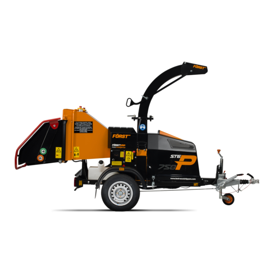
P a g e Introduction Thank you for becoming the owner of this Redwood Global Ltd, Forst ST6p woodchipping machine. By observing the contents of this manual, we hope the machine gives safe and productive service. This user manual is intended for the owner/operator to safely and effectively operate this machine and carry out routine maintenance between services. -
Page 5: Purpose Of Machine
P a g e Purpose of machine The Forst ST6p is designed to reduce wood material up to 150mm diameter to woodchip. This machine is capable of processing up to 5 tonnes of wood per hour. - Page 6 P a g e Exterior component identification Figure 1 TRIP BAR HOPPER TRAY LATCH HOPPER CHIPPING CHAMBER COVER CHUTE HOOD CHUTE MACHINE LIFTING EYE ENGINE COVER MANUFACTURER'S STATUTORY PLATE 10 SERIAL NUMBER 11 JOCKEY WHEEL HANDLE 12 VEHICLE CONNECTION LEAD 13 TOW HEAD 14 MACHINE LIGHT BOARD SOCKET 15 ENGINE COVER LATCH...
- Page 7 P a g e Figure 2 CHUTE HOOD LOCK HANDLE CHUTE HANDLE CHUTE ROTATION LOCK HANDLE BATTERY REMOVEABLE NUMBER PLATE HOLDER...
-
Page 8: Safety
P a g e Safety Safe working Before using this machine, make sure that you are trained and fluent in its operation. Know the location of and how to use all the safety features. Know how to control the feed and stop the machine in an emergency. Be familiar with the hazards and safe working practices to prevent injury and damage to property and machine. -
Page 9: Machine Lifting
P a g e 8. All personnel operating or feeding material into the machine must wear heavy duty non-snag clothing to help prevent being caught on material and drawn into the machine. The feed mechanism of this machine uses high powered hydraulic motors to drive sharp toothed rollers that feed material into the cutting blades. -
Page 10: Dos And Don'ts
P a g e DOs and DON’Ts DO NOT use machine in poor visibility DO stop the machine before making or insufficient light to see clearly. any adjustments, refuelling or DO NOT use or attempt to start the cleaning. machine without the discharge chute DO make sure the machine has or guards correctly and securely fitted. -
Page 11: Noise Test Information
P a g e | 10 Noise test information Machine Forst ST6p Notes Tested chipping 50 x 50mm sawn pine 4.2m in length. Noise levels above 85dB (A) will be experienced at the working position and within a 4 metre radius. Operators and personnel within a 4 metre radius must wear appropriate ear protection at all times while machine is in operation to prevent the risk of hearing damage. -
Page 12: Machine Operation
P a g e | 11 Machine operation STANDARD PROGRAMME OrRANGE BUTTON PROGRAMME MACHINE USE MACHINE USE TOUCH SENSOR HOPPER TOUCH SENSOR HOPPER STAGE STAGE Fold down hopper tray Fold down hopper tray Start engine. Start engine. Turn key to start engine and let go once Turn key to start engine and let go once engine has fired engine has fired... -
Page 13: Machine Control Panel, Start/Stop & Operating Settings
P a g e | 12 Machine control panel, start/stop & operating settings This machine is fitted with an engine PLC (Programmable Logic Controller) system that manages the engine, feed and all safety features. The control panel is located on the right side panel (see Figure 1). Feed and engine speed are controlled with a “No Stress”... - Page 14 P a g e | 13 Turn ignition key fully clockwise to crank engine. Display will automatically go to P1 If engine fails to start, turn key to off position and start process again. P1 shows Working Hours and charging indicator text at the screen bottom centre. P2 shows I/O tests.
- Page 15 P a g e | 14 To stop engine turn off with ignition key by turning fully anti- clockwise. P4 Crank Time – 3 Feed speed adjustment 1 CONTROL VALVE FEED SPEED ADJUSTMENT. POSITION INDICATED BY PIP. 0 = MINIMUM 10 = MAXIMUM Figure 5 The feed speed can be adjusted to suit the material being chipped see Figure 5.
-
Page 16: Emergency Stopping - Standard Program
To stop the feed rollers either tap the red stop button (2) or push the red stop bar (1) and the rollers will stop instantly. If any of these functions fail, turn off the machine and remove the key from the ignition switch and contact Redwood Global and ask for service. -
Page 17: Emergency Stopping - Orange Button Program
If any of these functions fail, turn off the machine and remove the key from the ignition switch and contact Redwood Global and ask for service. -
Page 18: Feed Jam & Blockages
P a g e | 17 Feed jam & blockages Be aware that whatever is fed into the machine has to come out of the chute. Always monitor the state of chip flow out of the chute. If this stops, STOP FEEDING MATERIAL IMMEDIATELY. -
Page 19: Transportation
P a g e | 18 1 REMOVE EYE BOLT NUT BOTH SIDES BEFORE LIFTING FEED ROLLER 2 INSERT TOP FEED ROLLER LIFTING TOOL INTO SLOT AND LIFT 3 INSERT M12 SCREW TO HOLD FEED IN OPEN POSITION Figure 6 Transportation ... -
Page 20: Attaching To The Vehicle Tow Hitch
P a g e | 19 Attaching to the vehicle tow hitch Check that the vehicle ball hitch is well greased. Raise the machine hitch by turning the jockey wheel handle anticlockwise until the hitch socket is above the vehicle hitch ball. ... -
Page 21: Routine Maintenance
P a g e | 20 Routine maintenance The following must be checked at least on a daily basis during use (also see Service schedule): Check engine oil. See Figure 9 Check hydraulic oil level. When the machine is new, the oil level may drop during initial use. -
Page 22: Engine Maintenance
P a g e | 21 Engine maintenance Please refer to the engine manual supplied with this machine for the following: Checking the engine oil. Changing the engine oil, oil filter and fuel filter. Fastener tightening torques Tightening torques for class 8.8 and 10.9 fasteners Class 8.8 Class 10.9 Nominal... -
Page 23: Service Schedule
P a g e | 22 Service schedule Service Schedule After first Every 8 After first After first Every 20 After first Every 50 Every Every Every Briggs engine Wood chipper 5 Hrs 10 Hrs 20 Hrs 50 Hrs 100 Hrs 200 Hrs 250 Hrs (Daily) - Page 24 P a g e | 23 Service schedule Service Schedule Every Every Every Every Every Every Every Every 12 Every 2 Every 5 Briggs engine Wood chipper 400 Hrs 500 Hrs 800 Hrs 1000 Hrs 1500 Hrs 2000 Hrs 3000 Hrs months years years...
-
Page 25: Covers: Engine, Chipping Chamber, Side Panels
P a g e | 24 Covers: engine, chipping chamber, side panels COVER OPENING SEQUENCE, A then B 1 ENGINE COVER LATCH 2 2x M12 SCREWS SECURE COVER IN CLOSED POSITION Figure 7 Figure 8 1 LEFT SIDE PANEL CAN BE REMOVED FOR ACCESS TO FEED ROLLER TENSION SPRING ANCHORS. -
Page 26: Engine Bay
P a g e | 25 SIDE PANELS CHIPPING CHAMBER COVER FIXING SCREWS TOP FEED ROLLER LIFTING TOOL SOCKET Engine bay AIR FILTER ENGINE OIL FILLER CAP HYDRAULIC OIL TANK FUEL FILTER CHIPPING CHAMBER COVER FIXING DIP STICK ANVIL CLAMP BOLT Figure 9... - Page 27 P a g e | 26 Figure 10 1 FLYWEEL PULLEY RETENTION PLATE 2 FLYWHEEL DRIVE BELTS 3 BELT TENSIONER DEVICE AND PULLEY 4 ENGINE OIL FILTER...
-
Page 28: Blade Changing
P a g e | 27 Blade Changing WARNING – Rigger Gloves must be worn whilst changing the blades WARNING – It is essential that only genuine parts are used guaranteeing the correct grade of Blade, bolt, washer and nut 1. -
Page 29: Blade Sharpening
P a g e | 28 Blade sharpening For optimum performance, blades need to be kept sharp. Minimum safe blade size after sharpening is shown in Figure 11. After sharpening, the blade gap must be re- set by using a blade shim as shown in Figure 12. -
Page 30: Hydraulic Oil Filter
P a g e | 29 1 SIDE ANVIL 2 ANVIL 3 OUTSIDE BLADE GAP 4 FLYWHEEL BLADE 5 INSIDE BLADE GAP Figure 13 Hydraulic oil filter... - Page 31 P a g e | 30 Use protective plastic gloves to keep oil off skin, dispose of oil and filter in an environmentally responsible manner. 1. The filter housing is accessed under the engine cover, in the top of the hydraulic tank.
- Page 32 P a g e | 31 Drive belt tension The flywheel V belts must be checked for tension and condition. If any belt shows signs of wear, surface damage, shredding, excessive glazing, or have been stretched to their limit, they must be replaced. Multiple belt drives must have all belts replaced at the same time.
-
Page 33: Battery
P a g e | 32 Battery Battery safety information 1. Battery acid is highly corrosive. For safety reasons, wear eye protection when handling a battery. Do not tilt battery as acid could escape from vents. 2. Keep children away from acid and batteries. 3. -
Page 34: Charging
P a g e | 33 6. Slacken the M8 battery clamp screw. 7. Remove battery. Clean with a moist anti-static cloth to avoid electrostatic discharge and explosion risk. Charge and check electrolyte level if appropriate. 8. Clean out battery tray. Apply a thin film of petroleum jelly to terminals to prevent corrosion. -
Page 35: Taking Battery Out Of Service
P a g e | 34 2. Only use batteries of the same voltage. 3. Switch off ignition on machine and support vehicle. The two must not touch and all lights/equipment must be turned off. 4. Referring to Figure 16, connect in the sequence of 1 – 2 – 3 – 4 as shown and as follows: Connect one end of the red jump lead to the machine battery positive (+) terminal. -
Page 36: Parts Lists
P a g e | 35 Parts lists Hopper tray touch sensor... -
Page 37: Chipping Chamber Assembly
P a g e | 36 Chipping chamber assembly Item No Pa rt No Des cri pti on Qua nti ty 12-11-020 Bea ri ng & hous i ng 12-10-075 G1/8i n BSPP 4mm ma l e s tud coupl i ng 12-A-010 Fl ywheel a s s y 12-01-064... - Page 38 P a g e | 37 Chipping chamber assembly - Bottom feed.
-
Page 39: Chipping Chamber Assembly - Bottom Feed & Anvil
P a g e | 38 Chipping chamber assembly – Bottom feed & Anvil. Item No Pa rt No Des cri pti on Qua nti ty 12-12-601 M12 x 50Lg 8.8 Hex Hea d s crew 12-14-015 M12 Spri ng wa s her DIN 128 12-14-003 M12 Wa s her ISO 7089 12-01-003 Anvi l cl a mp 12-01-013 Anvi l... -
Page 40: Chipping Chamber Assembly - Drive
P a g e | 39 Chipping chamber assembly - Drive Item No Part No Description Quantity 24-A-002 Belt tensioner with nylon pulley. 12-12-506 M10 x 25Lg 8.8 Hex Head screw 12-14-010 M10 Spring Washer DIN 128 12-14-009 M10 Washer ISO 7089 12-19-063 Pulley retainer 12-10-038 Taper lock bush 50 ID 12-10-299 Birn Pulley 507 OD x 44 wide 2 groove 1... -
Page 41: Chipping Chamber Assembly - Flywheel Drive
P a g e | 40 Chipping chamber assembly - Flywheel drive. Item No Part No Description Quantity 12-10-305 V Belt - B75... -
Page 42: Chipping Chamber Assembly - Bottom Feed Roller Cover
P a g e | 41 Chipping chamber assembly - Bottom feed roller cover. Item No Part No Description Quantity 12-12-504 M10 x 20Lg 8.8 Hex Head screw 2 12-14-010 M10 Spring Washer DIN 128 12-14-009 M10 Washer ISO 7089 12-03-045 Feed roller cover... -
Page 43: Chute Assembly
P a g e | 42 Chute assembly Item No Part No Description Quantity 12-19-056.B Chute clamp fab assy 12-20-001 Spring Pin Slotted 10 DIA x 30Lg ISO 8752 12-19-164 M16 Chute Clamp Assy. 12-19-051.B Chute fab assy 12-11-007 Plain bearing 12 ID, 16 OD, 22 flange x 10 Lg 12-14-003 M12 Washer ISO 7089 12-13-003... -
Page 44: Top Feed Roller Assembly
P a g e | 43 Top feed roller assembly... -
Page 45: Flywheel Assembly
P a g e | 44 Flywheel assembly... -
Page 46: Fuel Tank Assembly
P a g e | 45 Fuel tank assembly Item No Part No Description Quantity 24-02-003 Fuel tank 35L moulded assy 24-02-005 Petrol tank cap 12-14-008 M12 Bonded washer (Dowty) 2 12-10-027 Banjo M12 12-10-026 Banjo bolt M12... -
Page 47: Hydraulic Pump Assembly
P a g e | 46 Hydraulic Pump Assembly Item No. Part Number Description Quantity 12-24-061 Hydraulic single pump 8cc 12-12-403 M8 Bolt x 40mm 12-14-013 M8 Plain washer 24-03-036 Pump bracket assy. 12-14-013 M8 Plain washer 12-13-011 M8 Nyloc nut 12-12-302 M6 Bolt x 12mm 12-14-018... -
Page 48: Light Board Assembly
P a g e | 47 Light board assembly... -
Page 49: Belt Tensioner Assembly
P a g e | 48 Belt Tensioner assembly Item No. Part No. Description Quantity 24-01-060 Belt tensioner nylon pulley 24-05-003 Belt tensioner spacer 24-03-169 Belt tensioner plate 12-11-011 6304 2RS Deep groove ball bearing 12-12-211 M20 x 100 lg. 8.8 Hex bolt 12-10-182.P M20 Nyloc nut... -
Page 50: Running Gear - Hitch & Axle
P a g e | 49 Running gear – hitch & axle Please refer to maintenance instruction manual supplied with the machine. Hydraulics circuit diagram 1 Motor 2 Control valve 3 Test point 4 Tank Filter 5 Pump 6 Oil tank... -
Page 51: Electrical Circuit Diagram - Mechanical & Touch Sensor Hopper
P a g e | 50 Electrical circuit diagram – Mechanical & touch sensor hopper Engine Loom... -
Page 52: Decals
P a g e | 51 Decals Decal meaning: 1. Throttle movement relation to engine speed. 2. CE (Conformite Europeene or European Conformity) mark. Manufacturer’s declaration that the product complies with the essential requirements of the relevant European health, safety and environment protection legislation. 3. -
Page 53: Manufacturer's Statutory Plate
P a g e | 52 Manufacturer’s Statutory Plate Information on the Manufacturer’s Statutory Plate in line order from top to bottom is as follows: 1. Manufacturing company. 2. Vehicle type approval number and construction date. 3. 17 digit Vehicle Identification Number (VIN) construction. 4. -
Page 54: Warranty
To obtain warranty service please contact Redwood Global Ltd for the nearest approved Forst Dealer. Your nearest dealer can be obtained from Redwood Global Ltd at the address on the front of the User Manual. In the event of a failure Redwood Global Ltd must be notified within 7 working days. -
Page 55: Ce Certificate
Company contact details: Redwood Global Ltd, Unit 86, Livingstone Road, Walworth Business Park, Andover, Hampshire. SP10 5NS. United Kingdom Redwood Global Ltd declares that their: Wood Chippers listed as the following models ST6p Towed ST6 Towed & TR6 on Tracks ST8 Towed &...
Need help?
Do you have a question about the Forst ST6p and is the answer not in the manual?
Questions and answers