Table of Contents
Advertisement
Thank you for selecting the Atomic LS
two major goals; to simplify EFI and deliver better overall performance from your engine. Simplicity
is achieved through wired-less technology to ease installation plus the Atomic is simple to program
with no PC required! Performance is delivered through advanced control of the fuel and ignition, just
as you'd expect from MSD.
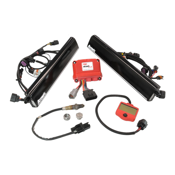
Parts Included:
2 – Integrated Fuel/ECU Rail Assemblies
1 - Power Module
1 - Handheld Monitor
1 - Wideband O2 Sensor, Bung and Plug
2 - MAP Sensor Adapter Harnesses
2 - Camshaft Sensor Harnesses, 1x and 4x
2 - Crankshaft Harnesses, 24x and 58x
4 - Injector Harnesses
1 - IAT Sensor and Grommet
Parts Required, Not Included:
• Injector O-Rings
• Fuel System: Fuel Pump, Regulator, Line
• LS1 and LS6 Installation Kit - PN 2955
For use with Master Kit PN 2950. Provides the
correct brackets and EV-1 injector connectors
for the early car intake manifolds identified by
a 3-bolt throttle body.
• Thread Sealer for Intake Bolts
Not legal for use on pollution controlled vehicles: The MSD Atomic LS EFI system is not CARB
DANGER
approved for use on emission controlled vehicles. This system is designed to control the EFI and
ignition on LS based engines being retro-fit into older vehicles that do not require emission controls.
WARNING
modifications must be carried out by a qualified automotive technician. Installation of fuel system
parts requires handling of gasoline. Ensure that work is performed in a well ventilated area with an
CAUTION
approved fire extinguisher nearby. Extinguish all open flames, prohibit smoking and eliminate all
sources of ignition in the area of the vehicle before beginning the installation.
When working with fuel systems, eye goggles and other safety apparel should be worn to protect
against debris and sprayed gasoline. The finished work must be thoroughly checked to ensure
NOTICE
there are no fuel leaks.
Atomic LS EFI
Master Kit LS2/LS3, PN 2950
EFI
System! MSD's Atomic EFI systems are designed with
Installation of this product requires detailed knowledge of automotive systems
and repair procedures. Installation of fuel system parts and any fuel tank
1 - TPS Sensor Harness
2 - 90° -6 AN fittings
4 - -6 AN fittings
1 - 15" High Pressure Fuel Hose
2 - Fuel Hose Clamps
4 - Installation Brackets
4 - Intake Manifold Bolts
8 - Injector Retainers
8 - 8/32" Socket Head Cap Screws
1 - 4G Micro SD Card
4 - Grommet, Sleeves and Mounting Screws
Advertisement
Table of Contents

Related Manuals for MSD Atomic LS EFI 2950

Summary of Contents for MSD Atomic LS EFI 2950
- Page 1 3-bolt throttle body. • Thread Sealer for Intake Bolts Not legal for use on pollution controlled vehicles: The MSD Atomic LS EFI system is not CARB DANGER approved for use on emission controlled vehicles. This system is designed to control the EFI and ignition on LS based engines being retro-fit into older vehicles that do not require emission controls.
- Page 2 There are different mounting brackets available for several of the key intake manifolds. MSD offers two Installation Kits that are supplied with different injector connects and fuel rail brackets for manifolds such as the LS1 or truck. They are described in the ‘Not Included’ list of parts above.
- Page 3 Following are some guidelines in helping set up a fuel system for your Atomic as well as components available separately from MSD. • The Atomic is capable of operating with a return or returnless style system. For best results with either system, MSD strongly recommends an in-tank pump.
- Page 4 In-Tank Pumps The MSD Atomic Fuel Pump (not supplied) can be used in the tank however it would require a sock, or filter element, on the pickup side. It is important to note that the wiring used to run the pump will need to meet requirements to be submersed in fuel.
- Page 5 4. Insert supplied plug in bung. Never run the vehicle with a WBO2 installed but not powered; it will damage the sensor. 5. When completing the Atomic EFI installation, remove the plug and insert the WBO2 for use. MSD suggests using a small amount of anti-seize on the threads.
- Page 6 INSTALLATION INSTRUCTIONS INSTALLING THE INTEGRATED FUEL/ECU RAILS The integrated fuel/ECU rails are supplied with the covers installed. The rails are designed to install to OEM intake manifolds and many aftermarket designs. To prepare the rails for installation, locate the four intake manifold bolts supplied with the Atomic LS Master Kit, as well as the four mounting brackets.
- Page 7 INSTALLATION INSTRUCTIONS 3. Locate the four injector harness pigtails. These need to be connected to the fuel rails (Figure 5). 4. With the brackets and injector pigtails installed on the intake manifold, it is time to install the injectors to the fuel rails.
- Page 8 INSTALLATION INSTRUCTIONS 7. Install the retaining bolts and washers to secure the fuel/ECU rails to the mounting brackets. Move between the retainers as they are tightened to ensure even pressure (Figure 8). 8. Connect the injector wiring, coil packs and other wiring.
- Page 9 CORRECT CLEAN, SQUARE CUT MSD supplies a length of fuel hose and two 90° -6AN fittings to prepare a fuel crossover line. The fittings are designed for use with the supplied hose and clamps. INCORRECT...
- Page 10 The Power Module of the Atomic EFI system handles high current circuits such as the fuel pump and WBO2. ® The unit has two ports for the MSD CAN system as CONTROLLER well as a wiring harness. The CAN ports will provide communication between the Power Module, the passenger side fuel/ECU rail and the Handheld Monitor.
- Page 11 INSTALLATION INSTRUCTIONS Power Module Color Function Battery 1, Connect to Positive Battery terminal. Black Ground, Connect to solid, clean engine ground. Orange Pump, Connect to Fuel Pump Positive terminal. Battery 2, Connect to Battery Positive terminal. Fan 1, Supplies ground to activate Fan 1 Blue Launch, Connect to 12 volts to activate 2-step RPM limit.
- Page 12 INSTALLATION INSTRUCTIONS ENGINE IDENTIFICATION INFORMATION GM has produced a number of different LS based engine platforms. When setting up your Atomic LS system, it is helpful to know the model engine you have. If you don’t know what engine you have, locate the casting number on the back of the block, below the driver's side cylinder head (Figure 16).
- Page 13 Coils: Once the engine type is selected, the OEM coil pack will be automatically loaded in the default calibration file. If a different coil or an MSD LS Coil pack is used, change the setting to the correct coil type (Figure 18).
- Page 14 INSTALLATION INSTRUCTIONS Fuel Injector: Once the engine type is selected above, the OEM style injector will be automatically loaded in the default calibration file. If a different injector is used, change the setting to the correct injector. Most LS based injectors have the part number stamped on them (Figure 19).
- Page 15 INSTALLATION INSTRUCTIONS Idle RPM Target: Select the rpm that the engine should idle at. The rpm range is adjustable in 25 rpm increments (Figure 20). Note: Running too high of an idle speed in an automatic transmission equipped vehicle with a stock torque converter can cause idle issues in gear.
- Page 16 INSTALLATION INSTRUCTIONS A/F Targets: The Atomic LS provides an option to set an air/fuel target for Idle, Part Throttle, Wide Open (WOT), Boost and an Auxiliary setting. The Atomic will use its self-learning technology to adjust the fuel delivery to meet the target air/ fuel ratio.
- Page 17 Racepak Dash: This setting allows the Atomic LS kit to interface with a Racepak dash such an IQ3. Disable is the default setting. Racepak offers an optional V-net sensor to connect their dash to the MSD Can-Bus connector (Figure 22). Speed Reference Setting...
- Page 18 INSTALLATION INSTRUCTIONS PRE-START CHECK LIST Before attempting to start the motor, run through the pre-start check list to ensure a safe and successful start. • Double-check all wiring • Power and ground leads are connected directly to the battery. • Red (Pin G) should be connected to a 12v ignition source that is hot in the RUN and START positions of the key cycle.
- Page 19 INSTALLATION INSTRUCTIONS The Atomic LS Dash is a live display when the engine is running. This is a brief description of each parameter in the Atomic LS Dash. ATOMIC LS DASH: Tach Displays engine RPM. Speed Displays Speed if speed if speed sensor is equipped and calibrated. Displays coolant temperature.
- Page 20 INSTALLATION INSTRUCTIONS DIAGNOSTICS There is a self-diagnosing system built into the Atomic EFI. Each covered parameter can show a status in one of three ways (Figure 24). • “OK”: the parameter is functioning normally. • “Error C”: there is currently an error occurring. •...
- Page 21 Open the Micro-SD card’s window on your computer. b. Drag and drop the MSD files into the folder. c. The files must remain in the main folder do NOT put them in a sub-folder. 4. Move the Micro-SD card to the Atomic EFI’s Handheld 5.
Need help?
Do you have a question about the Atomic LS EFI 2950 and is the answer not in the manual?
Questions and answers