Table of Contents
Advertisement
Quick Links
Advertisement
Table of Contents

Related Manuals for Lumel P18-0


Summary of Contents for Lumel P18-0
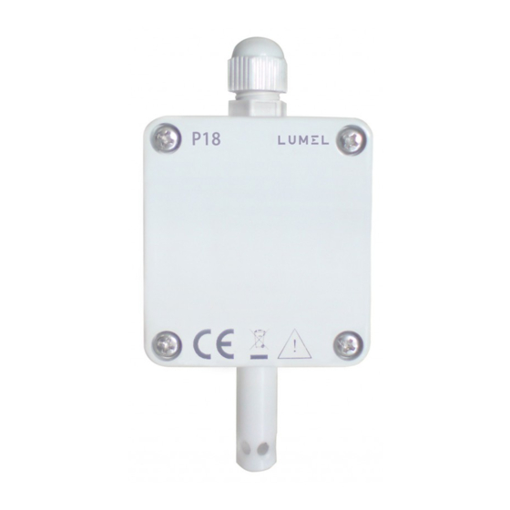
- Page 1 TEMPERATURE AND HUMIDITY TRANSDUCER TYPE USER’S MANUAL...
-
Page 3: Table Of Contents
CONTENTS 1. APPLICATION ................5 2. BASIC REQUIREMENTS, OPERATIONAL SAFETY ....5 3. INSTALLATION ................5 3.1. Assembly ....................5 3.2. Electrical Connections ................7 4. SERVICING ................9 4.1. Functions of the P18 Transducer ............10 4.2. Individual Characteristic of Analog Outputs ........11 4.3. RS-485 Interface ................13 4.4. Standard Parameters ................18 5. ACCESSORIES ................ 19 6. TECHNICAL DATA ..............20 7. ORDERING CODES ..............23 8. -
Page 5: Application
1. APPLICATION The P18 transducer is device destined for the continuous measurement and conversion of relative humidity and ambient temperature into a digital form and into a voltage or current standard signal. The transducer is fixed on a wall. The programming of the transducer is possible by means of the RS-485 interface. Applied sensor shields enable the application of the P18 transducer in various ambient conditions 2. BASIC REQUIREMENTS, OPERATIONAL SAFETY In the security scope, the transducer meets the requirements of the EN 61010 -1 standard. - Page 6 Fig.1. Overall Dimensions of the P18 Transducer Fig.2. Lay-out of Assembly Holes of the P18 Transducer...
-
Page 7: Electrical Connections
3.2. Electrical Connections The P18 transducer has 8 connecting terminals to which there is access after removing the cover of the transducer housing. For electrical connections, one must use a round wire with external dia- meter from 3.5 mm up to 6 mm. Before the transducer assembly, one must pass supplying wires through the packing. Twist the packing seal in order to obtain the leaktightness. If the packing seal is not twisted, we cannot ensure the required IP 65 leaktightness. - Page 8 Way of Electrical Signal Connection Table 1 Transducer without analog outputs Transducer with current outputs Transducer with voltage outputs One must use a spiral for the interface line connection. In case of the transducer work in an environment with high interference, one must apply shielded wires. The shield must be connected to the nearest PE point from the feeder side.
-
Page 9: Servicing
- i ndividual characteristics of analog outputs (for executions with analog outputs). There is the possibility to connect the transducer through another trans- mission media, like: ETHERNET, USB, using LUMEL S.A.’s converters. The transducer is equipped of one two-colour signalling diode. The diode pulsation means: - pulsing in green colour – measurements carrying out correctly, - pulsing in red colour –... -
Page 10: Individual Characteristic Of Analog Outputs
Measured and calculated values of the P18 transducer: - temperature T = measured - relative humidity RH = measured - dew-point 10000 A RH a = 2,1668 - absolute humidity 100 (T + 273,2) where: = temperature [ RH = relative humidity [%] = temperature of the dew-point [ = pressure of the satured water vapour (water vapour pressure) [mbar] = absolute humidity [g/m Coefficients for the dew-point Table 2 < 0 6.119866 7.926104 250.4138 0...50 6.1078... - Page 11 given coordinates of two points by the user, the transducer determines (from the system of equations) coefficients a and b of the individual characteristic. Y1Out = a X1In + b Y2Out = a X2In + b where: X1 In and X2 In - measured value Y1 Out i Y2 Out - expected value on the output.
-
Page 12: Rs-485 Interface
The configuration of the individual characteristic of analog outputs amounts to the introduction of suitable values X1, X2, Y1, Y2 in cor- responding registers to them from the range 4007 – 4014 tab.3. Values introduced in these registers must be integral values corresponding to set point values multiplied by the value 100. - Page 13 Set of parameters of the transducer serial link in the MODBUS protocol: - transducer address 1... 247 - baud rate 4800, 9600, 19200, 38400, 57600 bit/s - work modes - information unit 8N2, 8E1, 8O1, 8N1 - maximal response time 300 ms The configuration of serial link parameters consists on settlement of baud rate (register Baud rate), device address (register Address) and the type information (register Mode). Note: Each transducer connected to the communication network must have: unique address, different from other devices connected to the network, the same baud rate and information unit type.
- Page 14 4.3.3. Registers for Write and Readout Configuration Registers of the P18 Transducer Table 6. Address Name Range Description 4000 Identifier 0xAA Identifier of the P18 transducer 4001 Address 1...247 Device address 4002 Baud rate 0...4 Baud rate of the RS-485 interface (bit/s) 0: 4800 1: 9600 2: 19200 3: 38400 4: 57600 4003 Mode 0...3 Kind of transmission through the RS-485 interface 0: RTU 8N1 1: RTU 8N2...
- Page 15 4010 Y2 temperature 0...2000 Output value Y2 of temperature: c. current output [mA x 100] d. voltage output [Vx100] 4011 X1 humidity 0...10000 Measured value X1 of humidity [% x 100] 4012 Y1 humidity 0...2000 Output value Y1 of humidity: e. current output [mA x 100] f. voltage output [Vx100] 4013 X2 humidity 0...10000 Measured value X2 of humidity [% x 100] 4014 Y2 humidity 0...2000 Output value Y2 of humidity: g. current output [mA x 100] h. voltage output [Vx100] 4017 Status register 0...65535 Status register, description of bits below Bit 0 „1” transducer with current analog outputs Bit 1 „1” transducer with voltage analog outputs Bit 2 „1” the interval of averaging measurement result is expired, Bit 3,4 „0.0” steering up of 1 analog output - temperature...
- Page 16 Caution! The transducer checks as they come, values of the currently introduced parameter. In case, when the introduced value exceeds the upper or the lower change range given in the table above, the transducer does not carry out the parameter write. 4.3.4.
-
Page 17: Standard Parameters
4.4. Standard Parameters Standard Parameters of the P18 Transducer Table 8 Standard value Parameter Version Version with Version with description without analog the current output the voltage output outputs Address Baud rate 9600 9600 9600 Mode RTU 8N1 RTU 8N1 RTU 8N1 Measuring time 30 [s] 30 [s] 30 [s] X1 temperature... - Page 18 Fig. 5. Placement of the Jumper Setting Temporary Communication Parameters.
-
Page 19: Accessories
5. ACCESSORIES As a standard, the P18 transducer is equipped with a metallic shield of the sensor, destined only for indoors applications, for outdoors or indoors applications exposed to the possibility of water vapour condensation, it is recommended to use additional shields of the sensor (interchangeable), depending of the transducer working conditions. -
Page 20: Technical Data
6. TECHNICAL DATA Basic parameters: - range of relative humidity measurement (RH) 0...100%, without condensation - basic error of humidity conversion ± 2% of the range for RH=10...90% ± 3% for the remaining range - hysteresis of the humidity measurement ± 1% RH - basic range of temperature measurement - 20...60°C - basic error of temperature conversion calculated quantities ± 0.5% of the range absolute humidity (a) [g/m dew-point temperature (Td) [ - additional errors: - temperature influence ± 25% of the basic error/10°C RS-485 digital output: - transmission protocol MODBUS - baud rate 4800, 9600,19200,38400, 57600 bit/s - mode RTU: 8N2, 8E1, 8O1, 8N1 - maximal response time 300 ms Analog outputs: - current 4...20 mA - voltage... - Page 21 Rated operating conditions: - supply 9...24 V a.c./d.c. - consumption < 0.5 VA - ambient temperature - 20...23...85 - relative air humidity < 95% 0.5 m/sec - rate of air flow - pre-heating time 15 minutes - protection degree ensured by the housing IP 65 - fixing on a wall - weight 125 g - dimensions (35 ´ 58 ´ 118) mm - working position: i n applications non-exposed ● to a direct contact with water i n applications exposed ● to a direct contact with water with the sensor chamber directed towards the ground. Electromagnetic compatibility: - noise immunity acc. to EN 61000 -6-2 - noise emission acc. to EN 61000 -6-4 Security requirements acc.
-
Page 22: Ordering Codes
7. ORDERING CODES Ordering Codes of P18 Transducer Versions Table 10 Temperature and Humidity Transducer P18 - XX X Analog Outputs: without analog outputs current output: 4...20 mA voltage output: 0...10 V Execution: standard custom-made Acceptance Tests: without additional quality inspection requirements with an extra quality inspection certificate other requirements agreed with the customer* The code will be established after agreement with the manufacturer Example of Order: The code: P18-1- 00- 8 means P18 - Humidity and temperature transducer. 1 - current output: 4...20 mA 00 - standard version 8 - without additional quality inspection certificate. -
Page 23: Maintenance And Guarantee
8. MAINTENANCE AND GUARANTEE The P18 transducer does not require any periodical maintenance. In case of some incorrect operations: 1. In the period of 12 months from the date of purchase: One should take the transducer down from the installation and return it to the Manufacturer Quality Control Dept. If the unit has been used in compliance with the instructions, the Manufacturer garantees to repair it free of charge. - Page 24 PRECISION ENGINEERING and THERMOPLASTICS PARTS SUBCONTRACTING of ELECTRONIC DEVICES (SMT) PRESSURE CASTINGS and OTHER TOOLS QUALITY PROCEDURES: According ISO 9001 and ISO 14001 international requirements. All our instruments have CE mark. For more information, please write to or phone our Export Department. Lubuskie Zak³ady Aparatów Elektrycznych LUMEL S.A. ul. Sulechowska 1 65-022 Zielona Góra - Poland tel.: (48-68) 329 51 00 (exchange) fax: (48-68) 329 51 01 Export Department: e-mail: lumel@lumel.com.pl Tel.: (48-68) 329 53 02 or 53 04 http://www.lumel.com.pl Fax: (48-68) 325 40 91 e-mail: export@lumel.com.pl...
Need help?
Do you have a question about the P18-0 and is the answer not in the manual?
Questions and answers