Tektronix DPO3000 Series User Manual
Digital phosphor oscilloscopes
Hide thumbs
Also See for DPO3000 Series:
- Installation manual (31 pages) ,
- User manual (196 pages) ,
- Instruction manual (132 pages)

Related Manuals for Tektronix DPO3000 Series


Summary of Contents for Tektronix DPO3000 Series
- Page 1 DPO3000 Series Digital Phosphor Oscilloscopes User Manual www.tektronix.com 071-2410-01...
- Page 2 Copyright © Tektronix. All rights reserved. Licensed software products are owned by Tektronix or its subsidiaries or suppliers, and are protected by national copyright laws and international treaty provisions. Tektronix products are covered by U.S. and foreign patents, issued and pending. Information in this publication supersedes that in all previously published material.
- Page 3 Warranty 16 Tektronix warrants that the product will be free from defects in materials and workmanship for a period of three (3) years from the date of original purchase from an authorized Tektronix distributor. If the product proves defective during this warranty period, Tektronix, at its option, either will repair the defective product without charge for parts and labor, or will provide a replacement in exchange for the defective product.
-
Page 5: Table Of Contents
Connecting Your Oscilloscope to a Computer ..................DPO3000 Series Oscilloscopes User Manual... - Page 6 Starting and Stopping an Acquisition....................DPO3000 Series Oscilloscopes User Manual...
- Page 7 Saving and Recalling Setups ..................... . . DPO3000 Series Oscilloscopes User Manual...
- Page 8 Appendix: Warranted Specifications, Safety Certifications, and Electromagnetic Compatibility ........Index DPO3000 Series Oscilloscopes User Manual...
-
Page 9: General Safety Summary
Do not apply a potential to any terminal, including the common terminal, that exceeds the maximum rating of that terminal. Power Disconnect. The power cord disconnects the product from the power source. Do not block the power cord; it must remain accessible to the user at all times. DPO3000 Series Oscilloscopes User Manual... - Page 10 These terms may appear in this manual: WARNING. Warning statements identify conditions or practices that could result in injury or loss of life. CAUTION. Caution statements identify conditions or practices that could result in damage to this product or other property. DPO3000 Series Oscilloscopes User Manual...
- Page 11 DANGER indicates an injury hazard immediately accessible as you read the marking. WARNING indicates an injury hazard not immediately accessible as you read the marking. CAUTION indicates a hazard to property including the product. The following symbol(s) may appear on the product: DPO3000 Series Oscilloscopes User Manual...
-
Page 12: Environmental Considerations
The symbol shown below indicates that this product complies with the European Union’s requirements according to Directive 2002/96/EC on waste electrical and electronic equipment (WEEE). For information about recycling options, check the Support/Service section of the Tektronix Web site (www.tektronix.com). Mercury Notification. - Page 13 Environmental Considerations Restriction of Hazardous Substances This product has been classified as Monitoring and Control equipment, and is outside the scope of the 2002/95/EC RoHS Directive. DPO3000 Series Oscilloscopes User Manual...
-
Page 14: Preface
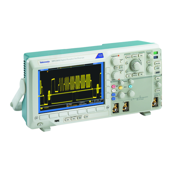
DPO3014 DPO3012 Key Features DPO3000 series instruments can help you verify, debug, and characterize electronic designs. Key features include: 500 MHz, 300 MHz, and 100 MHz bandwidths 2 and 4 channel models Sample rates up to 2.5 GS/s on all analog channels... -
Page 15: Conventions Used In This Manual
Built-in Ethernet port USB 2.0 device port for direct PC control of the oscilloscope using USBTMC protocol OpenChoice documentation and analysis software NI LabVIEW SignalExpress™ Tektronix Edition productivity and analysis software Remote viewing and control with e*Scope Remote control with VISA connectivity... - Page 16 Preface DPO3000 Series Oscilloscopes User Manual...
-
Page 17: Installation
Before Installation Unpack the oscilloscope and check that you received all items listed as standard accessories. The following pages list recommended accessories and probes, instrument options, and upgrades. Check the Tektronix Web site (www.tektronix.com) for the most current information. DPO3000 Series Oscilloscopes User Manual... - Page 18 Installation Standard Accessories Accessory Description Tektronix part number DPO3000 Series Oscilloscopes User Manual English (Option L0) 071-2410-XX French (Option L1) 071-2411-XX 071-2412-XX Italian (Option L2) German (Option L3) 071-2413-XX Spanish (Option L4) 071-2414-XX Japanese (Option L5) 071-2415-XX Portuguese (Option L6)
- Page 19 Traditional Chinese (option L8) Korean (Option L9) 335-1925-00 Russian (Option L10) 335-1926-00 For DPO3000 series: Probes One, 500 MHz, 10X passive probe per channel P6139A Front Cover Hard plastic cover to help protect the instrument 200-2524-00 DPO3000 Series Oscilloscopes User Manual...
- Page 20 161-0343-00 United Kingdom (Option A2) 161-0344-00 Australia (Option A3) 161-0346-00 Switzerland (Option A5) 161-0347-00 Japan (Option A6) 161-0342-00 China (Option A10) 161-0341-00 161-0349-00 India (Option A11) —— No power cord or AC adapter (Option A99) DPO3000 Series Oscilloscopes User Manual...
- Page 21 The extended video module enables triggering DPO3VID DPO3VID on a variety of standard HDTV signals, as well as on custom (non-standard) bilevel and trilevel video signals with 3 to 4,000 lines. TPA-BNC TekVPI to TekProbe II BNC Adapter TPA-BNC DPO3000 Series Oscilloscopes User Manual...
- Page 22 Documentation Browser CD or for download from www.tektronix.com/manuals DPO3000 Series Oscilloscopes Technical Describes the oscilloscope specifications and 071-2423-XX Reference Manual performance verification procedure. Available electronically on the Documentation Browser CD or for download from www.tektronix.com/manuals DPO3000 Series Oscilloscopes User Manual...
- Page 23 Service information on DPO3000 oscilloscopes manual DPO3000 Series Oscilloscopes Module Manual 071-2524-XX Installation The DPO3000 series oscilloscopes work with multiple optional probes. (See page 13, Connecting Probes.) Check the Tektronix Web site (www.tektronix.com) for the most current information. DPO3000 Series Oscilloscopes User Manual...
-
Page 24: Operating Considerations
Height, including feet but not handle: 203.2 mm (8 in) Width, 416.6 mm (16.4 in) Depth, 147.4 mm (5.8 in) Clearance: 51 mm (2 in) DPO3000 series Temperature: Operating: +0 °C to +50 °C Nonoperating: -40 °C to +71 °C DPO3000 Series Oscilloscopes User Manual... - Page 25 Acquisition System: 50 Ω and 75 Ω The maximum input voltage: 5 V with a peak at ±20. For Installation Category I measurements. Not for connection to Installation Category II, III, or IV circuits. DPO3000 Series Oscilloscopes User Manual...
- Page 26 To ensure proper cooling, keep the sides and rear of the instrument clear of obstructions. Total Probe Power: If the total probe power requirements exceed the available power from the oscilloscope, connect the external AC adapter (Tektronix part number 119-7465-XX) to the rear-panel Probe Power connector.
- Page 27 Temperature: Operating: -15 °C to +65 °C ( +5 °F to +149 °F) Nonoperating: -62 °C to +85 °C ( -80 °F to +185 °F) Altitude: ≤ 2,000 meters Pollution Degree: 2, Indoor use only DPO3000 Series Oscilloscopes User Manual...
- Page 28 2. Use a soft cloth dampened with water to clean the oscilloscope. Use an aqueous solution of 75% isopropyl alcohol for more efficient cleaning. CAUTION. To avoid damage to the surface of the oscilloscope or probes, do not use any abrasive or chemical cleaning agents. DPO3000 Series Oscilloscopes User Manual...
-
Page 29: Connecting Probes
ATE where you want the system to preset probe parameters. 2. TPA-BNC Adapter The TPA-BNC Adapter allows you to use TEKPROBE II probe capabilities, such as providing probe power, and passing scaling and unit information to the oscilloscope. DPO3000 Series Oscilloscopes User Manual... - Page 30 Some only pass the signal and there is no other communication. For more information on the many probes available for use with DPO3000 series oscilloscopes, refer to www.tektronix.com. DPO3000 Series Oscilloscopes User Manual...
-
Page 31: Securing The Oscilloscope
Installation Securing the Oscilloscope 1. Use a standard laptop computer style security lock to secure your oscilloscope to your location. DPO3000 Series Oscilloscopes User Manual... -
Page 32: Powering On The Oscilloscope
If you are working with static sensitive components, ground yourself. Static electricity that builds up on your body can damage static-sensitive components. Wearing a grounding strap safely sends static charges on your body to earth ground. DPO3000 Series Oscilloscopes User Manual... - Page 33 Installation To connect the power cord and power on the oscilloscope: DPO3000 Series Oscilloscopes User Manual...
-
Page 34: Powering Off The Oscilloscope
Installation Powering Off the Oscilloscope To power off the oscilloscope and remove the power cord: DPO3000 Series Oscilloscopes User Manual... -
Page 35: Functional Check
Functional Check Perform this quick functional check to verify that your oscilloscope is operating correctly. 1. Connect the oscilloscope power cable as described in Powering On the Oscilloscope. (See page 16.) 2. Power on the oscilloscope. DPO3000 Series Oscilloscopes User Manual... - Page 36 Installation 3. Connect the P6139A probe tip and reference lead to the PROBE COMP connectors on the oscilloscope. 4. Push Default Setup. DPO3000 Series Oscilloscopes User Manual...
- Page 37 (See page 22, Compensating a Passive Voltage Probe.) If no signal appears, rerun the procedure. If this does not remedy the situation, have the instrument serviced by qualified service personnel. DPO3000 Series Oscilloscopes User Manual...
-
Page 38: Compensating A Passive Voltage Probe
1. Follow the steps for the functional check. (See page 19, Functional Check.) 2. Check the shape of the displayed waveform to determine if your probe is properly compensated. Properly compensated Under compensated Over compensated DPO3000 Series Oscilloscopes User Manual... - Page 39 Installation 3. If necessary, adjust your probe. Repeat as needed. DPO3000 Series Oscilloscopes User Manual...
-
Page 40: Application Module Free Trial
After 30 days, you must purchase the module if you want to continue using the application. To see the date when your free trial period expires, push the front panel Utility button, push the lower-bezel Utility Page button, use multipurpose knob a to select Config, and push the lower-bezel About button. DPO3000 Series Oscilloscopes User Manual... -
Page 41: Installing An Application Module
To use these slots, install the module with the label facing away from you. Refer to the Tektronix 3000 Series Oscilloscopes Application Module Installation Instructions that came with your application module for instructions on installing and testing an application module. -
Page 42: Changing The User Interface Language
2. Push Utility Page. Utility Page 3. Turn multipurpose knob a and select Config. Config 4. Push Language from the resulting lower-bezel Utility Page Language Set Date & TekSecure About Time Config English Erase menu. Memory DPO3000 Series Oscilloscopes User Manual... - Page 43 6. If you choose to use English, be sure that the plastic front-panel overlay is removed. If you choose a language other than English, place the plastic overlay for the language that you desire over the front panel to display labels in that language. DPO3000 Series Oscilloscopes User Manual...
-
Page 44: Changing The Date And Time
1. Push Utility. 2. Push Utility Page. Utility Page 3. Turn multipurpose knob a and select Config. Config 4. Push Set Date & Time. System Language Set Date & TekSecure About Time Config English Erase Memory DPO3000 Series Oscilloscopes User Manual... - Page 45 (a and b) to set the time and date values. Display Date & Time On| Off Hour Minute Month Year 2007 6. Push OK Enter Date & Time. OK Enter Date & Time DPO3000 Series Oscilloscopes User Manual...
-
Page 46: Signal Path Compensation
5 mV/division or less. Failure to do so may result in the instrument not meeting warranted performance levels at those volts/div settings. To compensate the signal path: 1. Warm up the oscilloscope for at least 20 minutes. Remove all input signals (probes and cables) from channel inputs. Input signals with AC components adversely affect SPC. DPO3000 Series Oscilloscopes User Manual... - Page 47 Installation 2. Push Utility. 3. Push Utility Page. Utility Page 4. Turn multipurpose knob a and select Calibration Calibration. 5. Push Signal Path from the lower-bezel menu. Utility Page Signal Path Factory Calibration Pass Pass DPO3000 Series Oscilloscopes User Manual...
- Page 48 Service personnel use the factory calibration functions to calibrate the internal voltage references of the oscilloscope using external sources. Refer to your Tektronix field office or representative for assistance with factory calibration. NOTE. Signal Path Compensation does not include calibration to the probe tip. (See page 22, Compensating a Passive Voltage Probe.)
-
Page 49: Upgrading Firmware
1. Open up a Web browser and go to www.tektronix.com/software. Proceed to the software finder. Download the latest firmware for your oscilloscope on your PC. Unzip the files and copy the firmware.img file into the root folder of a USB flash drive. DPO3000 Series Oscilloscopes User Manual... - Page 50 Installation 2. Power off your oscilloscope. DPO3000 Series Oscilloscopes User Manual...
- Page 51 Installation 3. Insert the USB flash drive into the front-panel USB port on your oscilloscope. DPO3000 Series Oscilloscopes User Manual...
- Page 52 USB flash drive. Finally, if needed, contact qualified service personnel. NOTE. Do not power off the oscilloscope or remove the USB flash drive until the oscilloscope finishes installing the firmware. DPO3000 Series Oscilloscopes User Manual...
- Page 53 Installation 5. Power off the oscilloscope and remove the USB flash drive. DPO3000 Series Oscilloscopes User Manual...
- Page 54 Installation 6. Power on the oscilloscope. 7. Push Utility. DPO3000 Series Oscilloscopes User Manual...
- Page 55 10. Push About. The oscilloscope displays the Utility Page Language Set Date & TekSecure About Time Config English Erase firmware version number. Memory 11. Confirm that the version number matches that of the new firmware. DPO3000 Series Oscilloscopes User Manual...
-
Page 56: Connecting Your Oscilloscope To A Computer
To set up VISA communications between your oscilloscope and a computer: 1. Load the VISA drivers on your computer. You will find the drivers on the appropriate CD that comes with your oscilloscope or at the Tektronix software finder Web page (www.tektronix.com/software). DPO3000 Series Oscilloscopes User Manual... - Page 57 To communicate between the oscilloscope and a GPIB system, connect the oscilloscope to the TEK-USB-488 GPIB-to-USB Adapter with a USB cable. Then connect the adapter to your GPIB system with a GPIB cable. Cycle the power on the oscilloscope. DPO3000 Series Oscilloscopes User Manual...
- Page 58 USB is enabled. Enabled Settings Check USB on the lower-bezel menu to be sure that USB is enabled. If it is not enabled, push USB. Then push Enabled on the side-bezel menu. DPO3000 Series Oscilloscopes User Manual...
- Page 59 8. If you are using GPIB, push GPIB. Enter the Talk/Listen Address GPIB address on the side-bezel menu, using (a) 1 multipurpose knob a. This will set the GPIB address on an attached TEK-USB-488 Adapter. DPO3000 Series Oscilloscopes User Manual...
- Page 60 USB Device port Using e*Scope e*Scope lets you access any Internet-connected DPO3000 series oscilloscope from a browser on your workstation, PC, or laptop computer. No matter where you are, your oscilloscope is as close as the nearest browser. DPO3000 Series Oscilloscopes User Manual...
- Page 61 Ethernet cable. If you are connecting directly to your computer, you need a Crossover Ethernet Cable. If you are connecting to a network or a hub you need a Straight Through Ethernet Cable. 2. Push Utility. DPO3000 Series Oscilloscopes User Manual...
- Page 62 Installation 3. Push Utility Page. Utility Page 4. Turn multipurpose knob a and select I/O. 5. Push Ethernet Network Settings. Utility Page Ethernet GPIB Network Enabled Settings DPO3000 Series Oscilloscopes User Manual...
- Page 63 Test Connection NOTE. Depending on the type and speed of network to which your DPO3000 series oscilloscope is connected, you may not see the DHCP/BOOTP field update instantaneously after pressing the DHCP/BOOTP button. It may take a few seconds to update.
-
Page 64: Connecting A Usb Keyboard To Your Oscilloscope
Channel or Bus menus. Use the arrow keys on the keyboard to move the insertion point, and then type in a name or label. Labeling channels and buses makes the information on the screen easier to identify. DPO3000 Series Oscilloscopes User Manual... -
Page 65: Get Acquainted With The Instrument
Get Acquainted with the Instrument Get Acquainted with the Instrument Front-Panel Menus and Controls The front panel has buttons and controls for the functions that you use most often. Use the menu buttons to access more specialized functions. DPO3000 Series Oscilloscopes User Manual... - Page 66 Get Acquainted with the Instrument Using the Menu System To use the menu system: 1. Push a front-panel menu button to display the menu that you want to use. DPO3000 Series Oscilloscopes User Manual...
- Page 67 2. Push a lower-bezel button to select a menu item. If a pop-out menu appears, turn multipurpose knob a to select the desired choice. If a pop-up menu appears, press the button again to select the desired choice. DPO3000 Series Oscilloscopes User Manual...
- Page 68 If a pop-out menu appears, turn multipurpose knob a to select the desired choice. 4. To remove a side-bezel menu, push the lower-bezel button again or push Menu Off. DPO3000 Series Oscilloscopes User Manual...
- Page 69 6. Push Fine to turn off or on the ability to make smaller adjustments. Using the Menu Buttons Use the menu buttons to perform many functions in the oscilloscope. DPO3000 Series Oscilloscopes User Manual...
- Page 70 4. Acquire. Push to set the acquisition mode and adjust the record length. 5. Autoset. Push to perform an automatic setup of oscilloscope settings. 6. Trigger Menu. Push to specify trigger settings. DPO3000 Series Oscilloscopes User Manual...
- Page 71 USB flash drive. 9. Channel 1,2,3, or 4 Menu. Push to set vertical parameters for input waveforms and to display or remove the corresponding waveform from the display. DPO3000 Series Oscilloscopes User Manual...
- Page 72 12. M. Push to manage the math waveform, including the display or removal of the math waveform from the display. Using Other Controls These buttons and knobs control waveforms, cursors, and other data input. DPO3000 Series Oscilloscopes User Manual...
- Page 73 Push again to turn on the two vertical and two horizontal cursors. Push again to turn off all cursors. When the cursors are on, you can turn the multipurpose knobs to control their position. DPO3000 Series Oscilloscopes User Manual...
- Page 74 5. Waveform Intensity. Push to enable multipurpose knob a to control waveform display intensity and knob b to control graticule intensity. DPO3000 Series Oscilloscopes User Manual...
- Page 75 Turning it clockwise zooms in further. Turning it counterclockwise zooms out. 10. Play-pause button. Push to start or stop the automatic panning of a waveform. Control the speed and direction with the pan knob. DPO3000 Series Oscilloscopes User Manual...
- Page 76 13. → Next. Push to jump to the next waveform mark. 14. Horizontal Position. Turn to adjust the trigger point location relative to the acquired waveforms. Push Fine to make smaller adjustments. 15. Horizontal Scale. Turn to adjust the horizontal scale (time/division). DPO3000 Series Oscilloscopes User Manual...
- Page 77 19. Trigger Level. Turn to adjust the trigger level. Push this button to set the trigger level to the midpoint of the waveform. 20. Force Trig. Push to force an immediate trigger event. DPO3000 Series Oscilloscopes User Manual...
- Page 78 23. Vertical Scale. Turn to adjust the vertical scale factor of the corresponding waveform (volts/division). 24. Print. Push to print a screen image using the printer selected in the Utility menu. 25. Power switch. Push to power on or off the instrument. DPO3000 Series Oscilloscopes User Manual...
- Page 79 Save / Recall menu. 28. Default Setup. Push to perform an immediate restore of the oscilloscope to the default settings. 29. Menu Off. Push to clear a displayed menu from the screen. DPO3000 Series Oscilloscopes User Manual...
- Page 80 Identifying Items in the Display The items shown to the right may appear in the display. Not all of these items are visible at any given time. Some readouts move outside the graticule area when menus are turned off. DPO3000 Series Oscilloscopes User Manual...
- Page 81 Roll: In roll mode (40 ms/div or slower) PreVu: In this state, the oscilloscope is stopped or between triggers. You can change the horizontal or vertical position or scale to see approximately what the next acquisition will look like. DPO3000 Series Oscilloscopes User Manual...
- Page 82 4. The waveform record view shows the trigger location relative to the waveform record. The line color corresponds to the selected waveform color. DPO3000 Series Oscilloscopes User Manual...
- Page 83 Trig?: Waiting for trigger 6. The cursor readout shows time, amplitude, and delta (Δ) values for each cursor. For FFT measurements, it shows frequency and magnitude. For serial buses, the readout shows the decoded values. DPO3000 Series Oscilloscopes User Manual...
- Page 84 9. The top line of the record length/sampling rate readout shows the sampling rate (adjust with the Horizontal Scale knob). The bottom line shows the record length (adjust with the Acquire menu). DPO3000 Series Oscilloscopes User Manual...
- Page 85 Insert a negative time to capture more pretrigger information. With Delay Mode off, the bottom line shows the time location of the trigger within the acquisition, as a percentage. DPO3000 Series Oscilloscopes User Manual...
- Page 86 13. The channel readout shows the channel scale factor (per division), coupling, invert, and bandwidth status. Adjust with the Vertical Scale knob and the channel 1, 2, 3, or 4 menus. DPO3000 Series Oscilloscopes User Manual...
- Page 87 (ignoring the effect of offset). The icon colors correspond to the waveform colors. 15. The bus display shows decoded packet level information for serial buses or for parallel buses. DPO3000 Series Oscilloscopes User Manual...
-
Page 88: Front-Panel Connectors
11.5 pF ±2 pF. 3. PROBE COMP. Square wave signal source to compensate probes. Output voltage: 0 – 2.5V, amplitude ± 1% behind 1 kΩ ±2%. Frequency: 1 kHz. 4. Ground. 5. Application Module Slots. DPO3000 Series Oscilloscopes User Manual... -
Page 89: Side-Panel Connector
Get Acquainted with the Instrument Side-Panel Connector 1. Ground strap connector. This is a receptacle for a grounding strap. DPO3000 Series Oscilloscopes User Manual... -
Page 90: Rear-Panel Connectors
4. Video Out. Use the Video Out port (DB-15 female connector) to show the oscilloscope display on an external monitor or projector. 5. LAN. Use the LAN (Ethernet) port (RJ-45 connector) to connect the oscilloscope to a 10/100 Base-T local area network. DPO3000 Series Oscilloscopes User Manual... - Page 91 (one on the rear-panel and one on the front) to take advantage of USB flash drives, keyboards, and printers. 8. Power input. Attach to an AC power line with integral safety ground. (See page 8, Operating Considerations.) DPO3000 Series Oscilloscopes User Manual...
-
Page 92: Acquire The Signal
This section describes concepts of and procedures for setting up the oscilloscope to acquire the signal as you want it to. Setting Up Analog Channels Use front-panel buttons and knobs to set up your instrument to acquire signals using the analog channels. 1. Connect the P6139A or TekVPI probe to the input signal source. DPO3000 Series Oscilloscopes User Manual... - Page 93 NOTE. If you are using a probe that does not supply probe encoding, set the attenuation (probe factor) on the oscilloscope vertical menu for the channel to match the probe. 4. Push Autoset. DPO3000 Series Oscilloscopes User Manual...
- Page 94 The horizontal scale determines the size of the acquisition window relative to the waveform. You can scale the window to contain a waveform edge, a cycle, several cycles, or thousands of cycles. DPO3000 Series Oscilloscopes User Manual...
- Page 95 The label can have up to 32 characters. To label a channel or bus, follow these steps: 1. Push a front panel button for an input channel or a bus. DPO3000 Series Oscilloscopes User Manual...
- Page 96 3. Push Select Preset Label to view a list of Select Preset labels. Label 4. Turn multipurpose knob b to scroll through the list to find a suitable label. You can edit the label after you insert it if necessary. DPO3000 Series Oscilloscopes User Manual...
- Page 97 (See page 48, Connecting a USB Keyboard to Your Oscilloscope.) 6. If you do not have a USB keyboard connected, push the side- and lower-bezel arrow keys to position the insertion point. DPO3000 Series Oscilloscopes User Manual...
- Page 98 8. Push Select or Enter Character to let the oscilloscope know that you have picked the proper character to use. You can use the lower-bezel buttons to edit Enter Back Delete Clear Character Space the label as needed. DPO3000 Series Oscilloscopes User Manual...
-
Page 99: Using The Default Setup
10. Push Display Labels and select On to see Display Labels the label. On| Off Using the Default Setup To return the oscilloscope to its default settings: 1. Push Default Setup. DPO3000 Series Oscilloscopes User Manual... -
Page 100: Using Autoset
Autoset works with both the analog and digital channels. 1. Connect the analog probe, and then select the input channel. (See page 76, Setting Up Analog Channels.) 2. Push Autoset to execute an Autoset. DPO3000 Series Oscilloscopes User Manual... -
Page 101: Acquisition Concepts
Before a signal can be displayed, it must pass through the input channel where it is scaled and digitized. Each channel has a dedicated input amplifier and digitizer. Each channel produces a stream of digital data from which the instrument extracts waveform records. DPO3000 Series Oscilloscopes User Manual... - Page 102 Input signal Sampled points Digital values Real-Time Sampling DPO3000 series oscilloscopes use real-time Record points sampling. In real-time sampling, the instrument digitizes all of the points it acquires using a single trigger event.
- Page 103 fill a waveform record. Set this by pushing the Acquire button and using the resulting lower- and side-bezel menus. Trigger point: The zero time reference in a waveform record. It is shown on the screen by an orange T. DPO3000 Series Oscilloscopes User Manual...
-
Page 104: How The Analog Acquisition Modes Work
It is shown by an orange triangle. How the Analog Acquisition Modes Work Sample mode retains the first sampled point from each acquisition interval. Sample is the default mode. DPO3000 Series Oscilloscopes User Manual... - Page 105 Envelope uses Peak Detect for each individual acquisition. Average mode calculates the average value for each record point over a user-specified number of acquisitions. Average uses Sample mode for each individual acquisition. Use average mode to reduce random noise. DPO3000 Series Oscilloscopes User Manual...
-
Page 106: Changing The Acquisition Mode, Record Length, And Delay Time
Changing the Acquisition Mode, Record Length, and Delay Time Use this procedure to change the acquisition mode. 1. Push Acquire. 2. Push Mode. Mode Record Delay XY Display Set Horiz. Waveform Length Position to Display Sample |Off DPO3000 Series Oscilloscopes User Manual... - Page 107 Peak Detect, Hi Res and Sample modes all Envelope look the same. You can control the sample rate by setting the Horizontal scale and the Record Length. Average DPO3000 Series Oscilloscopes User Manual...
- Page 108 Choose among: 1000, 10 k, 100 k, 1 M, and 5 M points. 7. Push the lower-bezel Delay button to select On when you want to delay the acquisition relative to the trigger event. DPO3000 Series Oscilloscopes User Manual...
-
Page 109: Using Roll Mode
Roll mode gives a display similar to a strip chart recorder for low-frequency signals. Roll mode lets you see acquired data points without waiting for the acquisition of a complete waveform record. Roll mode is enabled when the trigger mode is auto and the horizontal scale is set to 40 ms/div or slower. DPO3000 Series Oscilloscopes User Manual... - Page 110 Switching to Envelope or Average acquisition mode, using math waveforms, turning on a bus, or switching to Normal trigger will disable Roll mode. Roll mode is disabled when you set the horizontal scale to 20 ms per division or faster. Push Run/Stop to halt Roll mode. DPO3000 Series Oscilloscopes User Manual...
-
Page 111: Setting Up A Serial Bus
Using Buses in Two Steps To quickly use serial bus triggering: 1. Push B1 or B2 and enter parameters of the bus to trigger on. You can separately use B1 and B2 to view two different buses. DPO3000 Series Oscilloscopes User Manual... - Page 112 Setting Up Bus Parameters NOTE. For all serial bus sources, use channels 1 through 4. To set up bus parameters: 1. Push B1 or B2 to bring up the lower-bezel bus menu. DPO3000 Series Oscilloscopes User Manual...
- Page 113 4. If you selected I2C above, push Define Inputs Define Thresholds Include B1 Label Bus Display Event Table Inputs R/W in and the desired side-bezel menu choices. Address You can assign the predefined SCLK Input or SDA Input to any channel. DPO3000 Series Oscilloscopes User Manual...
- Page 114 five bit code, 11110. The oscilloscope never includes these five bits in address readouts.) If you select No, then 7-bit addresses are displayed as seven bits and 10-bit addresses are displayed as ten bits. DPO3000 Series Oscilloscopes User Manual...
- Page 115 Bus Display Event Table Inputs RS-232 RS-232 9600-8-N Use the side-bezel menu to configure the bus. Use Normal polarity to trigger on RS-232 signals and Inverted polarity to trigger on RS-422, 485, and UART signals. DPO3000 Series Oscilloscopes User Manual...
- Page 116 Turn multipurpose knob a to select an End of Packet end-of-packet character. (Linefeed) 9. If you selected LIN above, push Configure. Define Thresholds Configure B1 Label Bus Display Event Table Inputs Use the side-bezel menu to configure the bus. DPO3000 Series Oscilloscopes User Manual...
- Page 117 Push LIN Standard, and turn multipurpose Standard knob a to select the appropriate standard. v1.x Push Include Parity Bits with Id to select Include Parity Bits whether or not to include parity bits. with Id DPO3000 Series Oscilloscopes User Manual...
- Page 118 Push Bus and Waveforms to display both views of the signal. Push the desired side-bezel menu choice to Binary display the bus data in hex, binary, decimal (for LIN), or ASCII (for RS-232) format. ASCII DPO3000 Series Oscilloscopes User Manual...
- Page 119 For an RS-232 bus, the table lists decoded bytes, or packets. Push Save Event Table to save the event table data in a .csv (spreadsheet) formatted file on the currently selected storage device. Bus information example: Bus and waveforms example: DPO3000 Series Oscilloscopes User Manual...
- Page 120 12. Push B1 or B2 and turn multipurpose knob a to move the bus display up or down on the screen. To trigger on serial bus conditions, refer to Triggering on Buses. (See page 121, Triggering on Buses.) DPO3000 Series Oscilloscopes User Manual...
- Page 121 Since the decode displays the MSB first, the oscilloscope reverses the order of the bits and displays 0110 1000. If the bus display is set to hex, the value displays as 68. If the bus display is set to ASCII, the value displays as h. DPO3000 Series Oscilloscopes User Manual...
- Page 122 RS-232 decoding, the stream of bytes will be displayed as packets. When decoding an RS-232 bus in ASCII mode, a large dot indicates that the value represents a character outside the printable ASCII range. DPO3000 Series Oscilloscopes User Manual...
-
Page 123: Trigger Setup
After a trigger is recognized, the instrument will not accept another trigger until the acquisition is complete and the holdoff time has expired. DPO3000 Series Oscilloscopes User Manual... - Page 124 Auto mode, when forcing triggers in the absence of valid triggering events, does not synchronize the waveform on the display. The waveform will appear to roll across the screen. If valid triggers occur, the display will become stable. DPO3000 Series Oscilloscopes User Manual...
- Page 125 When the instrument recognizes a trigger event, it disables the trigger system until acquisition is complete. In addition, the trigger system remains disabled during the holdoff period that Holdoffs follows each acquisition. DPO3000 Series Oscilloscopes User Manual...
- Page 126 Other trigger types use DC coupling only. Horizontal Position When Delay Mode is on, use horizontal position to acquire waveform detail in a region that is separated from the trigger location by a significant interval of time. DPO3000 Series Oscilloscopes User Manual...
- Page 127 find the source of the glitch. Alternatively, to see what is happening in your system as a result of the trigger event, make the posttrigger period large enough to capture data after the trigger. DPO3000 Series Oscilloscopes User Manual...
- Page 128 The level control determines where on that edge the trigger point occurs. The oscilloscope provides a long horizontal bar or bars across the graticule to temporarily show the trigger level. DPO3000 Series Oscilloscopes User Manual...
- Page 129 Trigger Setup 1. Turn the front-panel Trigger Level knob to adjust the trigger level without going to a menu. Push the knob to quickly set the trigger level to the midpoint of the waveform. DPO3000 Series Oscilloscopes User Manual...
-
Page 130: Choosing A Trigger Type
Trigger Setup Choosing a Trigger Type To select a trigger: 1. Push Trigger Menu. DPO3000 Series Oscilloscopes User Manual... - Page 131 The bus trigger requires use of the (B Trigger) DPO3EMBD, DPO3AUTO, or DPO3COMP Pulse application module. Width Runt Logic Setup & Hold Rise/Fall Time Video 3. Turn multipurpose knob a to select the desired trigger type. DPO3000 Series Oscilloscopes User Manual...
-
Page 132: Selecting Triggers
Edge triggers are the simplest and most commonly used trigger type, with both analog and digital signals. An edge trigger event occurs when the trigger source passes through a specified voltage level in the specified direction. DPO3000 Series Oscilloscopes User Manual... - Page 133 Trigger on pulses that are less than, greater than, equal to, or not equal to a specified time. You can trigger on positive or negative pulses. Pulse width triggers are primarily used on digital signals. DPO3000 Series Oscilloscopes User Manual...
- Page 134 For unclocked triggering, by default, triggering occurs when the selected condition goes true. You can also select triggering when the condition goes false, or time-qualified triggering. DPO3000 Series Oscilloscopes User Manual...
- Page 135 Rise/Fall Time Trigger on rise and fall times. Trigger on pulse edges that traverse between two thresholds at faster or slower rates than the specified time. Specify pulse edges as positive, negative, or either. DPO3000 Series Oscilloscopes User Manual...
- Page 136 C requires a DPO3EMBD module. SPI requires a DPO3EMBD module. CAN requires a DPO3AUTO module. RS-232, RS-422, RS-485, and UART require a DPO3COMP module. LIN requires either a DPO3AUTO module. (See page 24, Application Module Free Trial.) DPO3000 Series Oscilloscopes User Manual...
-
Page 137: Triggering On Buses
To set up the bus trigger: 1. If you have not already defined your bus using the front-panel B1 and B2 buttons, do so now. (See page 95, Setting Up a Serial Bus.) 2. Push Trigger Menu. DPO3000 Series Oscilloscopes User Manual... - Page 138 Bus. 5. Push Source Bus and turn multipurpose knob B1 (I2C) a to scroll through the source bus side menu B2 (CAN) until you select the bus that you want to trigger DPO3000 Series Oscilloscopes User Manual...
- Page 139 Tx Start Bit, Rx Start Bit, Tx End of Packet, Rx End of Packet,Tx Data, or Rx Data. If you are using the LIN bus trigger, you can trigger on Sync, Identifier, Data, Id & Data,Wakeup Frame, Sleep Frame, or Error. DPO3000 Series Oscilloscopes User Manual...
- Page 140 7 bit or 10 bit. Push the side-bezel Address button. Enter the address parameters of interest with multipurpose knobs a and b. Then push the lower-bezel menu Direction button and select the direction of interest: Read, Write, or Read or Write. DPO3000 Series Oscilloscopes User Manual...
- Page 141 7 bit or 10 bit. Push the side-bezel Data button. Enter the data parameters of interest with multipurpose knobs a and b. For more information on the I C address formats, refer to item 5 under Setting Up Bus Parameters. DPO3000 Series Oscilloscopes User Manual...
- Page 142 Then push the Number of Bytes button and enter the number of bytes with multipurpose knob a. If you select MOSI & MISO, push the lower-bezel Data button and enter the parameters of interest in the side-bezel menus. DPO3000 Series Oscilloscopes User Manual...
- Page 143 Read, Write, or Read or Write. If you have made a Trigger On selection of Data. Push the lower-bezel Data button and enter the parameters of interest with multipurpose knobs a and b. DPO3000 Series Oscilloscopes User Manual...
- Page 144 To use a rolling window to trigger on data, you define the number of bytes to match. Then the oscilloscope uses a rolling window to find any match within a packet, with the window rolling one byte at a time. DPO3000 Series Oscilloscopes User Manual...
- Page 145 To do so, choose the Tx End of Packet or the Rx End of Packet character as the Trigger On selection. DPO3000 Series Oscilloscopes User Manual...
-
Page 146: Checking Trigger Settings
The readouts differ for edge and the advanced triggers. 1. Trigger source = channel 1. 2. Trigger slope = rising. Edge trigger readout 3. Trigger level = 0.00 V. DPO3000 Series Oscilloscopes User Manual... -
Page 147: Using Sequence Trigger, A (Main) And B (Delayed)
Use the Edge trigger menu to set up the A trigger first. Then, to use the B trigger: 1. Push Trigger Menu. 2. Push Type. 3. Turn multipurpose knob a to select a trigger type of Sequence (B Trigger). This brings up the Sequence (B Trigger) menu. DPO3000 Series Oscilloscopes User Manual... - Page 148 Push a side-bezel button to select sequencing Time (a) 8 ns the B trigger after the A as Time or as Events. B Events Set to Minimum 5. Set the other Sequence Trigger parameters in the related side- and lower-bezel menus. DPO3000 Series Oscilloscopes User Manual...
- Page 149 Trigger Setup B Trigger After Delay Time The A trigger arms the instrument. Posttrigger acquisition starts on the first B edge after the trigger delay time. DPO3000 Series Oscilloscopes User Manual...
- Page 150 A trigger alone or the A and B triggers together, you can also use the horizontal position control to delay the acquisition by an additional amount. When using the B trigger, the A and B trigger types can only be Edge. DPO3000 Series Oscilloscopes User Manual...
-
Page 151: Starting And Stopping An Acquisition
Push Run/Stop to start acquisitions. The oscilloscope acquires repeatedly until you push the button again to stop the acquisition. Push Single to take a single acquisition. Single sets the trigger mode to Normal for the single acquisition. DPO3000 Series Oscilloscopes User Manual... -
Page 152: Display Waveform Data
You can use the channel as a trigger source whether or not it is displayed. Setting the Display Style and Persistence 1. To set the display style, push Acquire. DPO3000 Series Oscilloscopes User Manual... - Page 153 Display Waveform Data 2. Push Waveform Display. Mode Record Delay Set Horiz. Waveform XY Display Length Position to Display Sample |Off DPO3000 Series Oscilloscopes User Manual...
- Page 154 Display. Then push Triggered XY from the side menu. A data point from the first waveform specifies the horizontal location while the corresponding data point from the second waveform specifies the vertical location for each displayed point. DPO3000 Series Oscilloscopes User Manual...
- Page 155 REF1 versus REF2. On four-channel models, you can also use CH3 versus CH4, and REF3 versus REF4. When the XY Display is on, an upper window appears that displays data versus time. Setting the Graticule Style 1. To set the graticule style, push Utility. 2. Push Utility Page. Utility Page DPO3000 Series Oscilloscopes User Manual...
- Page 156 Display Waveform Data 3. Turn multipurpose knob a and select Display. Display 4. Push Graticule from the lower-bezel menu. Utility Page Backlight Graticule Screen Intensity Annotation Display Full High DPO3000 Series Oscilloscopes User Manual...
- Page 157 (The 143 mV/division selection is available in the coarse vertical scale settings for the channel when you set the trigger type to video.) The oscilloscope will automatically display the IRE graticule for NTSC signals, and the mV graticule for other video signals (PAL, SECAM, HDTV, and custom). DPO3000 Series Oscilloscopes User Manual...
- Page 158 Setting the LCD Backlight 1. Push Utility. 2. Push Utility Page. Utility Page 3. Turn multipurpose knob a and select Display. Display 4. Push Backlight Intensity. Utility Page Backlight Graticule Screen Intensity Annotation Display Full High DPO3000 Series Oscilloscopes User Manual...
-
Page 159: Setting Waveform Intensity
5. Select the intensity level from the resulting Backlight Intensity side-bezel menu. Choices are: High, Medium, and Low. High Medium Setting Waveform Intensity 1. Push the front-panel Intensity button. This will bring up the intensity readout on the display. DPO3000 Series Oscilloscopes User Manual... -
Page 160: Scaling And Positioning A Waveform
Use the horizontal controls to adjust the time base, adjust the trigger point, and to examine waveform details more closely. You can also use the Wave Inspector Pan and Zoom controls to adjust the display of waveforms. (See page 189, Using Wave Inspector to Manage Long Record Length Waveforms.) DPO3000 Series Oscilloscopes User Manual... - Page 161 Use the vertical controls to select waveforms, adjust the waveform vertical position and scale, and set input parameters. Push a channel menu button (1, 2, 3, or 4) as many times as needed and the associated menu items to select, add, or remove a waveform. DPO3000 Series Oscilloscopes User Manual...
-
Page 162: Setting Input Parameters
The math waveform, cursors, and automatic measurements remain active and valid when using preview. Setting Input Parameters Use the vertical controls to select waveforms, adjust the waveform vertical position and scale, and set input parameters. DPO3000 Series Oscilloscopes User Manual... - Page 163 On | More Use DC coupling to pass both AC and DC 50Ω components. Use AC coupling to block the DC component and show only the AC signal. Use Ground (GND) to display the reference potential. DPO3000 Series Oscilloscopes User Manual...
- Page 164 Select Full to set the bandwidth to the full oscilloscope bandwidth. Select 20 MHz to set the bandwidth to 20 MHz. 6. Push Label to create a label for the channel. (See page 79, Labeling Channels and Buses.) DPO3000 Series Oscilloscopes User Manual...
- Page 165 On the side-bezel menu, choose Set to 0 V to set the vertical offset to 0 V. For more information on offset, see Quick Tips. (See page 150, Quick Tips.) DPO3000 Series Oscilloscopes User Manual...
- Page 166 Using Probes with the TekProbe II and TekVPI Interfaces. When you attach a probe with the TekProbe II or the TekVPI interface, the oscilloscope sets the channel sensitivity, coupling, and termination resistance automatically to match the probe requirements. Tek Probe II probes require use of the TPA-BNC Adapter. DPO3000 Series Oscilloscopes User Manual...
-
Page 167: Positioning And Labeling Bus Signals
10X probe the scale factor is 10 V. If you apply excessive input voltage, the oscilloscope automatically switches to 1 MΩ termination to protect the internal 50 Ω or 75 Ω termination. For more details, refer to the specifications in the DPO3000 Series Oscilloscopes Technical Reference. Positioning and Labeling Bus Signals Positioning Bus Signals. - Page 168 To label a bus, do the following steps: 1. Push the appropriate front-panel bus button. 2. Push Label. Bus (B1) Define Thresholds (B1) Label Bus Display Event Table Inputs Parallel Parallel (See page 79, Labeling Channels and Buses.) DPO3000 Series Oscilloscopes User Manual...
-
Page 169: Annotating The Screen
Display Waveform Data Annotating the Screen You can add your own text to the screen by doing the following: 1. Push Utility. 2. Push Utility Page. Utility Page 3. Turn multipurpose knob a and select Display. Display DPO3000 Series Oscilloscopes User Manual... - Page 170 Alternatively, use a US-style USB keyboard to type in characters. (See page 48, Connecting a USB Keyboard to Your Oscilloscope.) To reposition the annotated text, press the side-bezel Position button and turn multipurpose knobs a and b, as desired. DPO3000 Series Oscilloscopes User Manual...
-
Page 171: Analyze Waveform Data
Select from features such as cursors, automatic measurements, statistics, math, and FFT. Taking Automatic Measurements To take an automatic measurement: 1. Push Measure. 2. Push Add Measurement. Add Mea- Remove Indicators Bring Configure surement Measure- Cursors on Cursors ment More Screen DPO3000 Series Oscilloscopes User Manual... - Page 172 Part of the waveform is above or below the display. To obtain a proper numerical measurement, turn the vertical scale and position knobs to make all of the waveform appear in the display. DPO3000 Series Oscilloscopes User Manual...
-
Page 173: Selecting Automatic Measurements
final value. Positive Duty The ratio of the positive pulse width to the signal period expressed as a percentage. The duty Cycle cycle is measured on the first cycle in the waveform or gated region. DPO3000 Series Oscilloscopes User Manual... - Page 174 The duration of a burst (a series of transient events) and is measured over the entire waveform or gated region. Phase The amount of time that one waveform leads or lags another waveform, expressed in degrees where 360° makes up one waveform cycle. See also Delay. DPO3000 Series Oscilloscopes User Manual...
- Page 175 Positive Overshoot = (Maximum – High) / Amplitude x 100%. Negative This is measured over the entire waveform or gated region and is expressed as: Overshoot Negative Overshoot = (Low – Minimum) / Amplitude x 100%. DPO3000 Series Oscilloscopes User Manual...
- Page 176 The most positive peak voltage. Max is measured over the entire waveform or gated region. The most negative peak voltage. Min is measured over the entire waveform or gated region. DPO3000 Series Oscilloscopes User Manual...
- Page 177 The true Root Mean Square voltage over the entire waveform or gated region. Cycle RMS The true Root Mean Square voltage over the first cycle in the waveform or the first cycle in the gated region. DPO3000 Series Oscilloscopes User Manual...
- Page 178 A voltage over time measurement. The measurement is the area over the first cycle in the waveform or the first cycle in the gated region expressed in volt-seconds. The area above the common reference point is positive, and the area below the common reference point is negative. DPO3000 Series Oscilloscopes User Manual...
-
Page 179: Customizing An Automatic Measurement
Gating confines the measurement to a certain portion of a waveform. To use: 1. Push Measure. 2. Push More as many times as needed to select Add Mea- Remove Indicators Bring Configure surement Measure- Cursors On Cursors Gating from the resulting pop-up menu. ment More Screen DPO3000 Series Oscilloscopes User Manual... - Page 180 Analyze Waveform Data 3. Position the gates from the side-bezel menu Gating options. (Full Record) Screen Between Cursors Bring Cursors On Screen DPO3000 Series Oscilloscopes User Manual...
- Page 181 Statistics characterize the stability of measurements. To adjust statistics: 1. Push Measure. 2. Push More as many times as needed to select Add Mea- Remove Indicators Bring Configure surement Measure- Cursors On Cursors Statistics from the resulting pop-up menu. ment More Screen DPO3000 Series Oscilloscopes User Manual...
- Page 182 On| Off standard deviation calculations. Mean & Std Dev Samples (a) | Reset Statistics Snapshot To see all the single-sourced measurements at one moment in time: 1. Push Measure. DPO3000 Series Oscilloscopes User Manual...
- Page 183 Statistics from the resulting ment More Screen pop-up menu. 3. Turn multipurpose knob a to select the Measurement Type of Snapshot. 4. Push OK Snapshot All Measurements. Snapshot All Mea- surements 5. View results. DPO3000 Series Oscilloscopes User Manual...
- Page 184 : 10.40 V : -8.800 V Ampl : 16.80 V Pk-Pk : 19.20 V Mean : -5.396 V CycleMean : -5.396 V : 7.769 V CycleRMS : 8.206 V Area : -21.58mVs CycleArea : -654.6μVs DPO3000 Series Oscilloscopes User Manual...
- Page 185 1. Push Measure. 2. Push More as many times as needed to select Add Mea- Remove Indicators Bring Configure surement Measure- Cursors On Cursors Reference Levels from the resulting pop-up ment Screen More menu. DPO3000 Series Oscilloscopes User Manual...
- Page 186 Use High and Low reference to calculate rise High Ref and fall times. (a) 90.0 % Use Mid reference primarily for measurements Mid Ref between edges, such as pulse widths. 50.0 % 50.0 % Low Ref 10.0 % - Set to Defaults DPO3000 Series Oscilloscopes User Manual...
-
Page 187: Taking Manual Measurements With Cursors
They are attached to the selected waveform. Four screen cursors appear. Two are vertical and two are horizontal. They are no longer specifically attached to a waveform. For example, the first time you push Cursors, the state might be off. DPO3000 Series Oscilloscopes User Manual... - Page 188 3. Push Select. This turns the cursor linking on and off. If linking is on, turning multipurpose knob a moves the two cursors together. Turning multipurpose knob b adjusts the time between the cursors. DPO3000 Series Oscilloscopes User Manual...
- Page 189 Pushing Fine also changes the sensitivity of other knobs as well. 5. Push Cursors again. This will put the cursors into screen mode. Two horizontal bars and two vertical bars span the graticule. DPO3000 Series Oscilloscopes User Manual...
- Page 190 7. Push Select. This makes the horizontal cursors active and the vertical ones inactive. Now, as you turn the multipurpose knobs, the horizontal cursors will move. Push Select again to make the vertical cursors active again. DPO3000 Series Oscilloscopes User Manual...
- Page 191 You can take timing measurements with cursors on digital channels, but not amplitude measurements. 9. Push Cursors again. This will turn off the cursor mode. The screen will no longer display the cursors and the cursor readout. DPO3000 Series Oscilloscopes User Manual...
- Page 192 Δ Readout: The Δ readouts indicate the difference between the cursor positions. a Readout: Indicates that the value is controlled by multipurpose knob a. b Readout: Indicates that the value is controlled by multipurpose knob b. DPO3000 Series Oscilloscopes User Manual...
-
Page 193: Using Math Waveforms
Create math waveforms to support the analysis of your channel and reference waveforms. By combining and transforming source waveforms and other data into math waveforms, you can derive the data view that your application requires. DPO3000 Series Oscilloscopes User Manual... - Page 194 (M) Label Math Math 3. On the side-bezel menu, set the sources to either channel 1, 2, 3, 4, or reference waveforms R1, R2, R3, or R4. Choose the +, –, x, or ÷ operators. DPO3000 Series Oscilloscopes User Manual...
- Page 195 You can zoom in on math waveforms using the inner knob of the Pan-Zoom control. Use the outer knob for positioning the zoomed area. (See page 189, Using Wave Inspector to Manage Long Record Length Waveforms.) DPO3000 Series Oscilloscopes User Manual...
-
Page 196: Using Fft
You can match these frequencies with known system frequencies, such as system clocks, oscillators, or power supplies. 1. Push Math. 2. Push FFT. Dual Wfm Advanced (M) Label Math Math DPO3000 Series Oscilloscopes User Manual... - Page 197 Hanning Window choices are: Rectangular, Hamming, Hanning, and Blackman-Harris. 6. Push the side-bezel Horizontal button to Horizontal 625kHz activate multipurpose knobs a and b to pan 1.25kHz/div and zoom the FFT display. DPO3000 Series Oscilloscopes User Manual...
- Page 198 Use the default dBV RMS scale to see a detailed view of multiple frequencies, even if they have very different amplitudes. Use the linear RMS scale to see an overall view of how all frequencies compare to each other. DPO3000 Series Oscilloscopes User Manual...
- Page 199 This is a very good window for measuring amplitude accuracy but less so for resolving frequencies. Use Hanning for measuring sine, periodic, and narrow band random noise. This window works on transients or bursts where the signal levels before and after the event are significantly different. DPO3000 Series Oscilloscopes User Manual...
-
Page 200: Using Advanced Math
Using Advanced Math The advanced math feature lets you create a custom math waveform expression that can incorporate active and reference waveforms, measurements, and/or numeric constants. To use this feature: 1. Push Math. DPO3000 Series Oscilloscopes User Manual... - Page 201 Analyze Waveform Data 2. Push Advanced Math. Dual Wfm Advanced Math Math 3. Use the side-bezel menu buttons to create custom expressions. DPO3000 Series Oscilloscopes User Manual...
- Page 202 2. Turn multipurpose knob a to select Intg(. 3. Push Enter Selection. 4. Turn multipurpose knob a to select channel 1. 5. Push Enter Selection. 6. Turn multipurpose knob a to select ). 7. Push OK Accept. DPO3000 Series Oscilloscopes User Manual...
-
Page 203: Using Reference Waveforms
1. Push Ref R. This brings up the lower-bezel reference menu. 2. Use the resulting lower-bezel menu selections (R1) | (On) (R2) | (Off) (R3) | (Off) (R4) | (Off) to display or select a reference waveform. 3-May-07 DPO3000 Series Oscilloscopes User Manual... - Page 204 Select the reference waveform and then adjust it with a multipurpose knob. You can do this whether acquisition is running or not. If a reference waveform is selected, scaling and repositioning of the reference waveform operates the same way whether zoom is turned on or off. DPO3000 Series Oscilloscopes User Manual...
-
Page 205: Using Wave Inspector To Manage Long Record Length Waveforms
The Wave Inspector controls (zoom/pan, play/pause, marks, search) help you to efficiently work with long record length waveforms. To magnify a waveform horizontally, turn the Zoom knob. To scroll through a zoomed waveform, turn the Pan knob. The Pan-Zoom Control consists of: 1. An outer pan knob 2. An inner zoom knob DPO3000 Series Oscilloscopes User Manual... - Page 206 1. Rotate the inner knob on the Pan-Zoom control clockwise to zoom in on a selected portion of the waveform. Rotate the knob counterclockwise to zoom back out. 2. Alternatively, enable or disable the zoom mode by pushing the zoom button. DPO3000 Series Oscilloscopes User Manual...
- Page 207 Panning a Waveform While the zoom feature is on, you can use the pan feature to quickly scroll through the waveform. To use pan: DPO3000 Series Oscilloscopes User Manual...
- Page 208 Turn it counterclockwise to pan backwards. The further you turn the knob, the faster the zoom window pans. Playing and Pausing a Waveform Use the play-pause feature to automatically pan through a waveform record. To use it: DPO3000 Series Oscilloscopes User Manual...
- Page 209 Use this maximum rotation feature to replay a portion of the waveform that you just saw and want to see again. DPO3000 Series Oscilloscopes User Manual...
- Page 210 Search marks provide a way to mark a waveform region for reference. You can set marks automatically with search criteria. You can search for and mark regions with particular edges, pulse widths, runts, logic states, rise/fall times, setup and hold, and bus search types. DPO3000 Series Oscilloscopes User Manual...
- Page 211 3. Investigate your waveform by moving from search mark to search mark. Use the next ( →) or previous (←) arrow button to jump from one marked location to another, without adjusting any other controls. DPO3000 Series Oscilloscopes User Manual...
- Page 212 2. Select the search type desired from the Search Search Source Slope Threshold Type lower-bezel menu. 0.00V Edge The search menu is similar to the trigger menu. 3. From the side-bezel menu, turn on the search. DPO3000 Series Oscilloscopes User Manual...
- Page 213 Custom (User) marks are saved with the waveform when the waveform is saved and when the setup is saved. Automatic search marks are not saved with the waveform when the waveform is saved. However, you can easily recapture them by reusing the search function. The search criteria are saved in the saved setup. DPO3000 Series Oscilloscopes User Manual...
- Page 214 RS-232, RS-422, RS-485, UART: Search for Tx Start Bit, Rx Start Bit, Tx End of Packet, Rx End of Packet, Tx Data, Rx Data, Tx Parity Error, Rx Parity Error. LIN: Search for Synch, Identifier, Data, ID & Data, Wakeup Frame, Sleep Frame, Error DPO3000 Series Oscilloscopes User Manual...
-
Page 215: Save And Recall Information
For waveforms, the XXXX is an integer from 0000 to 9999. The YYY is the channel of the waveform, and can be one of the following: CH1, CH2, CH3, or CH4 for the analog channels MTH for a math waveform DPO3000 Series Oscilloscopes User Manual... - Page 216 Editing File, Directory, Reference Waveform, or Instrument Setup Names. Give files descriptive names that you can recognize at a later date. To edit file names, directory names, reference waveform and instrument setup labels: 1. Push Save / Recall Menu. DPO3000 Series Oscilloscopes User Manual...
- Page 217 3. For waveform or setup files, enter the file To File manager by pushing the side-bezel menu To File item. 4. Turn multipurpose knob a to scroll through the file structure. (See page 199, External File Structure.) DPO3000 Series Oscilloscopes User Manual...
- Page 218 (See page 79, Labeling Channels and Buses.) 7. Push the Menu Off button to cancel the save operation, or push a side-bezel menu OK Save item to complete the operation. OK Save DPO3000 Series Oscilloscopes User Manual...
-
Page 219: Saving A Screen Image
Assign File Utilities Screen Waveform Waveform Setup menu. Save| to Image Setup Save Screen Image 3. From the side-bezel menu, push File Format File Format .png repeatedly to select among: .tif, .bmp, and .png formats. DPO3000 Series Oscilloscopes User Manual... -
Page 220: Saving And Recalling Waveform Data
Waveform data consists of the numeric values for each point in the waveform. It copies the data, as opposed to a graphical image of the screen. To save the current waveform data or to recall previously stored waveform data: DPO3000 Series Oscilloscopes User Manual... - Page 221 Save the information externally to a file on a USB flash drive. Alternatively, save the information internally to one of the two reference memory files on 2-channel model or one of the four reference files on 4-channel model oscilloscopes. DPO3000 Series Oscilloscopes User Manual...
- Page 222 Save Waveform screen button, and then select one of the reference waveform locations. Four-channel models have four reference locations. Two-channel models have two reference locations. Saved waveforms contain only the most recent acquisition. Gray-scale information, if any, is not saved. DPO3000 Series Oscilloscopes User Manual...
- Page 223 Displaying a Reference Waveform. To display a waveform stored in nonvolatile memory: 1. Push Ref R. 2. Push R1, R2, R3, or R4. (On) (Off) (Off) (Off) (R1) | (R2) | (R3) | (R4) | DPO3000 Series Oscilloscopes User Manual...
- Page 224 2. Push the R1, R2, R3, or R4 lower-bezel button (R1) | (R2) | (R3) | (R4) | (On) (Off) (Off) (Off) to remove the reference waveform from the display. The reference waveform is still in nonvolatile memory and can be displayed again. DPO3000 Series Oscilloscopes User Manual...
-
Page 225: Saving And Recalling Setups
GPIB addresses. To save the setup information: 1. Push Save / Recall Menu. 2. Push Save Setup or Recall Setup from the Save Save Save Setup Recall Recall Assign File Utilities Screen Waveform Waveform Setup lower-bezel menu. Save| to Image Setup DPO3000 Series Oscilloscopes User Manual... - Page 226 To File button. To Setup 2 – more – 4. If you are saving information to a USB flash drive, turn multipurpose knob a to scroll through the file structure. (See page 199, External File Structure.) DPO3000 Series Oscilloscopes User Manual...
- Page 227 5. Save the file. Save to Selected File Quick Tips Recalling the Default Setup. Push the front-panel Default Setup button to initialize the oscilloscope to a known setup. (See page 83, Using the Default Setup.) DPO3000 Series Oscilloscopes User Manual...
-
Page 228: Saving With One Button Push
Save button will save current waveform data to the defined USB drive. 1. To define the Save button behavior, push Save/Recall Menu. 2. Push Assign Save to button. Save Save Save Setup Recall Recall Assign File Utilities Screen Waveform Waveform Setup Save| to Image Setup DPO3000 Series Oscilloscopes User Manual... - Page 229 Save to Screen Image Waveform Setup 4. From now on, when you push Save the oscilloscope will perform the action that you just specified rather than requiring you to navigate through the menus each time. DPO3000 Series Oscilloscopes User Manual...
-
Page 230: Printing A Hard Copy
Connect your printer to a USB port on the rear or front panel of the oscilloscope. Alternatively, you can print to networked printers through the Ethernet port. Set Up Print Parameters To set up the oscilloscope to print hard copies: 1. Push Utility. DPO3000 Series Oscilloscopes User Manual... - Page 231 To add a USB printer to the list, plug the printer into the USB port. The oscilloscope will automatically recognize most printers. To add an Ethernet printer to the list, refer to the next topic. (See page 217, Printing Over Ethernet.) DPO3000 Series Oscilloscopes User Manual...
- Page 232 5. Select the image orientation (portrait or landscape). Landscape Portrait 6. Choose Ink Saver On or Off. The On selection will print out a copy with a clear (white) background. Ink Saver on Ink Saver off DPO3000 Series Oscilloscopes User Manual...
- Page 233 Save and Recall Information Printing Over Ethernet To set up the oscilloscope to print over Ethernet: 1. Connect an Ethernet cable to the rear-panel Ethernet port. 2. Push Utility. DPO3000 Series Oscilloscopes User Manual...
- Page 234 Save and Recall Information 3. Push Utility Page. Utility Page 4. Turn multipurpose knob a and select Print Print Setup Setup. 5. Push Select Printer. Utility Page Select Orientation Ink Saver Printer Print Setup Landscape DPO3000 Series Oscilloscopes User Manual...
- Page 235 If you are using a USB keyboard, use the arrow keys to position the insertion point and type in the printer name. (See page 48, Connecting a USB Keyboard to Your Oscilloscope.) ABCDEFGHIJKLMNOPQRSTUVWXYZ abcdefghijklmnopqrstuvwxyz 0123456789_=+-!@#$%^&*()[]{}<>/~’”\|:,.? DPO3000 Series Oscilloscopes User Manual...
- Page 236 10. Push the down arrow key to move the character Add Printer cursor down a row to the Server Name field. 11. Turn multipurpose knob a and push Select or Enter Character as often as needed to enter the name. DPO3000 Series Oscilloscopes User Manual...
- Page 237 14. When done, push OK Accept. NOTE. If you have multiple printers connected to the oscilloscope at the same time, the oscilloscope will print to the printer listed in the Utility> Utility Page> Print Setup> Select Printer menu item. DPO3000 Series Oscilloscopes User Manual...
- Page 238 Once you have connected a printer to your oscilloscope and set up print parameters, you can print current screen images with a single push of a button: Push the printer icon button in the lower left corner of the front panel. DPO3000 Series Oscilloscopes User Manual...
-
Page 239: Erasing Oscilloscope Memory
Replaces the current front-panel setup and all stored setups with the default setup Displays a confirmation or warning message, depending on whether the verification is successful or unsuccessful To use TekSecure: 1. Push Utility. 2. Push Utility Page. Utility Page DPO3000 Series Oscilloscopes User Manual... - Page 240 Language Set Date & TekSecure About Time Erase Config English Memory 5. Push OK Erase Setup and Ref Memory from Erase the side-bezel menu. Setup & Ref Memory To cancel the procedure, push Menu Off. DPO3000 Series Oscilloscopes User Manual...
- Page 241 Save and Recall Information 6. Power off the oscilloscope, and then power it back on to complete the process. DPO3000 Series Oscilloscopes User Manual...
-
Page 242: Using Application Modules
(See page 25, Installing an Application Module.) Refer to the DPO3000 Series Oscilloscopes Application Module Installation Instructions that came with your application module for instructions on installing and testing an application module. Some modules are described in the following list. Additional modules may be available. -
Page 243: Application Examples
If you need to see a signal in a circuit, but you do not know the signal amplitude or frequency, connect the probe from channel 1 of the oscilloscope to the signal. Then display the signal and measure its frequency and peak-to-peak amplitude. DPO3000 Series Oscilloscopes User Manual... - Page 244 When you are using more than one channel, the autoset function sets the vertical controls for each channel and uses the lowest-numbered active channel to set the horizontal and trigger controls. Selecting Automatic Measurements The oscilloscope can take automatic measurements of most displayed signals. To measure signal frequency and peak-to-peak amplitude: DPO3000 Series Oscilloscopes User Manual...
- Page 245 Source from the side menu and turn multipurpose knob b to select the channel from which you want to measure. Push OK Add Measurement from the side menu. Repeat this process to select the Peak-to-peak measurement. DPO3000 Series Oscilloscopes User Manual...
- Page 246 Application Examples 4. Push Menu Off. 5. Observe that the measurements appear on the screen and update as the signal changes. DPO3000 Series Oscilloscopes User Manual...
- Page 247 Connect two oscilloscope channels to the amplifier input and output as shown. Measure both signal levels and use these measurements to calculate the gain. To display the signals connected to channels 1 and 2: DPO3000 Series Oscilloscopes User Manual...
- Page 248 Application Examples 1. Push channel 1 and channel 2 to activate both channels. 2. Push Autoset. To select measurements for the two channels: 1. Push Measure to see the measurement menu. DPO3000 Series Oscilloscopes User Manual...
- Page 249 If needed, press Source and turn multipurpose knob b to select channel 1. Push OK Add Measurement from the side menu. Repeat this process to select channel 2 and again push OK Add Measurement from the side menu. DPO3000 Series Oscilloscopes User Manual...
- Page 250 In this example, you want to verify that the incoming signal to digital equipment meets its specifications. Specifically, the transition time from a low logic level (0.8 V) to a high logic level (2.0 V) must be 10 ns or less. DPO3000 Series Oscilloscopes User Manual...
- Page 251 3. Turn multipurpose knob a to select the Rise Time measurement. If needed, press Source from the side menu and turn multipurpose knob b to select the channel from which you want to measure. Push OK Add Measurement from the side menu. DPO3000 Series Oscilloscopes User Manual...
- Page 252 You can customize the rise time measurement to measure the signal transition time between any two reference levels. You can set each of these reference levels to a specific percent of the signal amplitude or to a specific level in vertical units (such as volts or amperes). DPO3000 Series Oscilloscopes User Manual...
- Page 253 Now you want to measure the width of each displayed pulse. You can use measurement gating to select a specific pulse to measure. To measure the second pulse: 2. Push Measure. DPO3000 Series Oscilloscopes User Manual...
- Page 254 Push OK Add Measurement from the side menu. 5. Push More repeatedly until you select Gating from the popup menu. 6. Select Between Cursors from the side-bezel menu to choose measurement gating using Between cursors. Cursors DPO3000 Series Oscilloscopes User Manual...
- Page 255 Application Examples 7. Place one cursor to the left and one cursor to the right of the second pulse. 8. View the resulting width measurement (160 ms) for the second pulse. DPO3000 Series Oscilloscopes User Manual...
-
Page 256: Analyzing Signal Detail
In this example, you have a noisy signal displayed on the oscilloscope, and you need to know more about it. You suspect that the signal contains much more detail than you can currently see in the display. DPO3000 Series Oscilloscopes User Manual... - Page 257 The signal appears noisy. You suspect that noise is causing problems in your circuit. To better analyze the noise: 1. Push Acquire. 2. Push Mode on the lower-bezel menu. Mode Record Delay Set Horiz. Waveform XY Display Length Position to Display Sample |Off DPO3000 Series Oscilloscopes User Manual...
- Page 258 Application Examples 3. Push Peak Detect on the side-bezel menu. Sample Peak Detect Hi Res Envelope Average 4. Push Intensity and turn multipurpose knob a to see the noise more easily. DPO3000 Series Oscilloscopes User Manual...
- Page 259 1 ns, even when the time base is set to a slow setting. Peak-detect and the other acquisition modes are explained earlier in this manual. (See page 85, Acquisition Concepts.) DPO3000 Series Oscilloscopes User Manual...
- Page 260 Now you want to analyze the signal shape and ignore the noise. To reduce random noise in the oscilloscope display: 1. Push Acquire. 2. Push Mode. Mode Record Delay Set Horiz. Waveform XY Display Length Position to Display Sample |Off 3. Push Average on the side-bezel menu. Average DPO3000 Series Oscilloscopes User Manual...
- Page 261 Averaging reduces random noise and makes it easier to see detail in a signal. In the example to the right, a ring shows on the rising and falling edges of the signal when the noise is removed. DPO3000 Series Oscilloscopes User Manual...
- Page 262 You can use the cursors to take quick measurements on a waveform. To measure the ring frequency at the rising edge of the signal: 1. Push channel 1 to select the channel 1 signal. 2. Push Measure. 3. Push Configure Cursors. Add Mea- Remove Indicators Bring Configure surement Measure- Cursors On Cursors ment More Screen DPO3000 Series Oscilloscopes User Manual...
- Page 263 Hz (1/s) as the unit of measurement. 5. Push Cursors repeatedly until the two vertical bar cursors appear on the selected waveform. 6. Place one cursor on the first peak of the ring using multipurpose knob a. DPO3000 Series Oscilloscopes User Manual...
- Page 264 Application Examples 7. If the cursor readout says that the cursors are linked, push Select to unlink them. 8. Place the other cursor on the next peak of the ring using multipurpose knob b. DPO3000 Series Oscilloscopes User Manual...
-
Page 265: Triggering On A Video Signal
Application Examples 9. The cursor Δ readout shows the measured ring frequency is 227 kHz. Triggering on a Video Signal The oscilloscope supports triggering on NTSC, SECAM, and PAL signals. DPO3000 Series Oscilloscopes User Manual... - Page 266 The video output is an NTSC standard signal. Use the video signal to obtain a stable display. To trigger on the video fields: 1. Push Trigger Menu. DPO3000 Series Oscilloscopes User Manual...
- Page 267 4. Push Video Standard, and turn multipurpose Type Video Source Trigger On Mode Standard knob a to scroll through the standards until you Video All Lines Auto 525/NTSC & Holdoff select 525/NTSC. 5. Push Trigger On. DPO3000 Series Oscilloscopes User Manual...
- Page 268 6. Select Odd Fields. Odd Fields If the signal had been noninterlaced, you could choose to trigger on All Fields. 7. Turn the Horizontal Scale knob to see a complete field across the screen. 8. View results. DPO3000 Series Oscilloscopes User Manual...
- Page 269 Triggering on Lines. To look at the video lines in the field: 1. Push Trigger Menu. 2. Push Type. Type 3. Turn multipurpose knob a to scroll through the Video trigger type side menu until you select Video. DPO3000 Series Oscilloscopes User Manual...
- Page 270 5. Select All Lines. All Lines To trigger on a specific line, select Line Number, and use multipurpose knob a to select the line number. 6. Adjust Horizontal Scale to see a complete video line across the screen. DPO3000 Series Oscilloscopes User Manual...
-
Page 271: Capturing A Single-Shot Signal
To set up for a single-shot acquisition: 1. Adjust the Vertical Scale and Horizontal Scale to appropriate ranges for the signal you expect to see. DPO3000 Series Oscilloscopes User Manual... - Page 272 4. Select Sample. 5. Push Trigger Menu. 6. Push Slope and 7. Turn the Trigger Level knob to adjust the trigger level to a voltage midway between the open and closed voltages of the replay. DPO3000 Series Oscilloscopes User Manual...
- Page 273 Application Examples 8. Push Single (single sequence). When the relay opens, the oscilloscope triggers and captures the event. The Single sequence button disables auto triggering so that only a valid triggered signal is acquired. DPO3000 Series Oscilloscopes User Manual...
- Page 274 When the next acquisition is captured with the new vertical and horizontal settings, you can see more detail about the relay contact opening. You can now see that the contact bounces several times as it opens. DPO3000 Series Oscilloscopes User Manual...
- Page 275 2. Turn the Pan knob to place the center of the zoom box close to where the relay contact begins to open. 3. Turn the Zoom knob to magnify the waveform in the zoom window. DPO3000 Series Oscilloscopes User Manual...
- Page 276 Application Examples The ragged waveform and the inductive load in the circuit suggest that the relay contact may be arcing as it opens. DPO3000 Series Oscilloscopes User Manual...
-
Page 277: Correlating Data With A Tla5000 Logic Analyzer
The iView External Oscilloscope Cable allows you to connect your logic analyzer to a Tektronix oscilloscope. This enables communication between the two instruments. For DPO3000 series oscilloscopes, you also need a TEK-USB-488 adaptor. The Add External Oscilloscope wizard, which is available from the TLA application System menu, guides you through the process of connecting the iView cable between your logic analyzer and oscilloscope. - Page 278 Application Examples To do this: 1. Select Add iView External Oscilloscope from the logic analyzer System menu. DPO3000 Series Oscilloscopes User Manual...
-
Page 279: Tracking Down Bus Anomalies
Application Examples 2. Select your model of oscilloscope. 3. Follow the on-screen instructions, and then click Next. 4. See your Tektronix Logic Analyzer documentation for more information on correlating data between your Tektronix oscilloscope and logic analyzer. Tracking Down Bus Anomalies In this example, you are testing your new I C circuit. - Page 280 First, you will display and acquire the bus signal by setting up the bus parameters and trigger. Then, you will search through each packet with the search/mark functions. NOTE. Triggering on I C, SPI, CAN, LIN, RS-232, RS-422, RS-485, and UART bus signals requires use of an appropriate DPO3EMBD, DPO3AUTO, or DPO3COMP Serial Triggering and Analysis Module. DPO3000 Series Oscilloscopes User Manual...
- Page 281 Application Examples 1. Connect the channel 1 probe to the clock line. 2. Connect the channel 2 probe to the data line. 3. Push Autoset. DPO3000 Series Oscilloscopes User Manual...
- Page 282 C bus in the resulting screen menus. 5. Push Trigger Menu. 6. Push Type to select Bus. Enter trigger Type Source Bus Trigger On Address Direction Mode B1 (I2C) Address Read Auto parameters in the resulting screen menus. & Holdoff DPO3000 Series Oscilloscopes User Manual...
- Page 283 Jump back with the left arrow key. Do you have all the packets that you expected to have? If not, at least you have narrowed your search down to the last packet sent. DPO3000 Series Oscilloscopes User Manual...
-
Page 284: Troubleshooting An Rs-232 Bus
First, you will display and acquire the digital signal. Then, you will look at both the analog and digital representations of the signal. Finally, you will search through each RS-232 byte with the search/mark functions. DPO3000 Series Oscilloscopes User Manual... - Page 285 NOTE. Triggering on RS-232 bus signals requires use of the DPO3COMP Serial Triggering and Analysis Module. (See page 24, Application Module Free Trial.) 1. Connect the desired analog probe tip to the desired test point. DPO3000 Series Oscilloscopes User Manual...
- Page 286 RS-232, and enter the parameters of the bus in the resulting screen menus. 6. Push the Bus Display lower-bezel button, push the Bus and Waveforms side-bezel button, and push the ASCII side-bezel. DPO3000 Series Oscilloscopes User Manual...
- Page 287 9. Push Search, push the Search lower-bezel button, and select On in the side-bezel menu. 10. Push Search Type. Use multipurpose knob a to select Bus. Push Search For and select the desired search, such as for the Tx Start Bit. DPO3000 Series Oscilloscopes User Manual...
- Page 288 Application Examples 11. Push the Previous and Next Mark buttons to navigate through the record. 12. Push Zoom and Pan to see the areas of interest and analyze the results. DPO3000 Series Oscilloscopes User Manual...
-
Page 289: Appendix: Warranted Specifications, Safety Certifications, And Electromagnetic Compatibility
2 mV to 4.98 mV/div 1 mV/div to 1.99 mV/div DPO3034 and DC to 300 MHz DC to 250 MHz DC to 150 MHz DPO3032 Instrument 1 mV/div to 1 V/div DPO3014 and DC to 100 MHz DPO3012 DPO3000 Series Oscilloscopes User Manual... - Page 290 ±2.0% for Coarse setting of 2 mV/div, derated at 0.100%/°C above 30 °C ±1.5% for Coarse settings of 5 mV/div and above, derated at 0.100%/°C above 30 °C ±3.0% for all Fine V/div settings, derated at 0.100%/°C above 30 °C DPO3000 Series Oscilloscopes User Manual...
- Page 291 European Union Compliance: Low Voltage Directive 2006/95/EC, as Amended by 93/68/EEC EN61010–1 2001 Safety Requirements for Electrical Equipment for Measurement, Control. and Laboratory Use Additional Compliance: IEC61010–1 2001 Safety Requirements for Electrical Equipment for Measurement, Control, and Laboratory Use DPO3000 Series Oscilloscopes User Manual...
- Page 292 EN 55011, Class A IEC 61000-3-2 IEC 61000-3-3 Immunity IEC 61000-4-2 IEC 61000-4-3 IEC 61000-4-4 IEC 61000-4-5 IEC 61000-4-6 IEC 61000-4-8 IEC 61000-4-11 Australia EMC Framework, demonstrated per Emission Standard AS/NZS 2064 (Industrial, Scientific, and Medical Equipment) DPO3000 Series Oscilloscopes User Manual...
- Page 293 Cursors, 57, 171, 247 Amplitude measurement, 160 Bandwidth, x, 148 Default Setup, 63, 77, 83 Annotating the screen, 153 Before Installation, 1 Fine, 53, 57, 58, 59, 60, 62 Application modules, 25, 226 Blackman-Harris FFT window, 184 DPO3000 Series Oscilloscopes User Manual...
- Page 294 Trigger level, 61 Aux Out, 74 Default Setup, 83, 211 Trigger menu, 114, 250 Probe Power, 74 button, 63, 77, 83 Utility, 26, 28, 31, 55, 139, 142, Video port, 74 menu, 63 153, 214 DPO3000 Series Oscilloscopes User Manual...
- Page 295 File system, 199, 206 Grid, 141 Erase setup and ref memory, 223 Fine, 58 intensity, 143 Ethernet, xi, 43, 45, 46 Fine button, 53, 57, 59, 60, 62 IRE, 141 port, 74 Firmware upgrade, 33 mV, 141 DPO3000 Series Oscilloscopes User Manual...
- Page 296 Horizontal scale, 60, 144, 182, 252, Impedance, 148 ments, 157 254, 255, 259 Indicator, waveform baseline, 71 setup analog channels, 76 and math waveforms, 179 Infinite persistence, 139 setup bus parameters, 96 DPO3000 Series Oscilloscopes User Manual...
- Page 297 Utility, 26, 28, 55, 62, 139, 153, FFT, 180 menu, 56 Vertical, 55, 146 waveforms, 177 Menu Off button, 63, 230 Label bus, 151 Max measurement, 160 Min measurement, 160 LabView, 40 Mean measurement, 161 Mode, roll, 93 LAN port, 74 DPO3000 Series Oscilloscopes User Manual...
- Page 298 Offset vertical, 149 P6139A, 11 Print, 215 OpenChoice, xi, 2 Portrait, 204, 216 Ethernet, 217 Operating specifications, 8 Position hard copy, 214 Orientation of the image, 204, 216 bus, 151 Print button, 62 Outer knob, 59 DPO3000 Series Oscilloscopes User Manual...
- Page 299 206 Rise Time measurement, 157 Cursor, 67, 176 screen images, 203 Rise/Fall trigger, defined, 119 Horizontal position/scale, 69 setups, 209 Rising Edge Count measurement, 162 Record length/sampling rate, 68 waveforms, 203 RMS measurement, 161 DPO3000 Series Oscilloscopes User Manual...
- Page 300 Signal path compensation, 30 LIN bus, 128 P6139A, 11 Single button, 61, 135, 237, 257 Logic, defined, 118 Termination, 148 Single sequence, 94, 135 modes, 108, 115 Test button, 54 Slope, trigger, 112 point, 87 DPO3000 Series Oscilloscopes User Manual...
- Page 301 114, 250 DPO3000, 8 menu, 55, 146 Trigger modes Menu knob, 62 Auto, 108 Normal, 108 offset, 151 Wave Inspector, x, 189 Offset, 149 Trigger types, defined, 116 Waveform position, 145 Triggering on Buses, 121 DPO3000 Series Oscilloscopes User Manual...
- Page 302 DPO3000, 8 button, 59 play, 191 Width graticule size, 192 play-pause, 193 DPO3000, 8 Horizontal, 259 record defined, 87 knob, 59, 190 removing, 136 search and mark, 194 user marks, 194 cursors, 177 zoom, 190 DPO3000 Series Oscilloscopes User Manual...
Need help?
Do you have a question about the DPO3000 Series and is the answer not in the manual?
Questions and answers