Table of Contents
Advertisement
Advertisement
Table of Contents

Subscribe to Our Youtube Channel
Summary of Contents for Emco-test DuraJet G5
- Page 2 Hardness Tester Introduction DuraJet 10 G5 Instruction manual Original instruction manual DuraJet G5 A2015-05 EN EMCO-TEST Prüfmaschinen GmbH Kellau 174 A-5431 Kuchl Tel: +43 6244 20438 – Fax: +43 6244 20438-8 office@emcotest.com – www.emcotest.com...
-
Page 3: Table Of Contents
Hardness Tester Introduction DuraJet 10 G5 Contents Introduction Preface Safety notes Manufacturer's notes Icons and Typographic Conventions Technical Data Startup Transporting the Machine Scope of Supply Weight and Dimensions Installing the Machine Initial Startup Design and Functions Design, Methods and Data Interfaces Control Unit Basic Operation Switching the Machine On and Off... - Page 4 Hardness Tester Introduction DuraJet 10 G5 External machine control via hardware interface Foot button Replacing the Fuses Replacing the Test Anvil Test Methods and Indenters 7-11 Messages and Problems...
-
Page 5: Introduction
Hardness Tester Introduction DuraJet 10 G5 1 Introduction Preface Our hardness testing machines represent state-of-the-art technology and comply with current norms and standards. Both the hardware and software in our machines can be upgraded on an ongoing basis. As a result, you can ensure that the technology in your machine is always up-to-date. - Page 6 Hardness Tester Introduction DuraJet 10 G5 Do not work with the machine for too long or when you are unable to concentrate Work time properly. The machine must not come into contact with water. Protect the machine from Protection from splashing.
-
Page 7: Manufacturer's Notes
Hardness Tester Introduction DuraJet 10 G5 Manufacturer's notes The rating plate sits at the right-hand side on the base. It shows the information that is Rating plate required to identify the machine. Manufacturer information Type name Serial number Mains voltage Nominal motor voltage External fuse Number of the circuit diagram... - Page 8 Hardness Tester Introduction DuraJet 10 G5 the installation location is contaminated, the machine must be operated in a separate closed test cell. The machine may only be operated by persons who have been properly trained in the operation, maintenance and repair of the machine, and are aware of the risks involved. All accident prevention and safety instructions for operating the machine must be observed.
-
Page 9: Icons And Typographic Conventions
Hardness Tester Introduction DuraJet 10 G5 Icons and Typographic Conventions The following safety instructions are used in this document. The sequence starts with Safety instructions the most important information, and shows the importance of the messages. A safety instruction always begins with the hazard sign, the signal word, and a text box that explains the hazard point and gives handling instructions. - Page 10 Hardness Tester Introduction DuraJet 10 G5 The following icons and typographic conventions are used in this instruction manual: Icons Crushing hazard indicates a risk of crushing, threatening life and limb of persons. Electric current indicates a risk of electric current, threatening life and limb of persons. Danger indicates a risk that threatens life and limb of persons.
-
Page 11: Technical Data
Hardness Tester Introduction DuraJet 10 G5 Technical Data Test loads Technical data 9.8-2450N [kgf] 1-250kg Test anvil/nose cone/test unit Test unit drive [1] DC motor Standard support [mm] Diameter 25 Nose cone support [mm] Diameter 15 Nose cone drilling [mm] Diameter 8 Test anvil dimensions Width x depth [mm]... - Page 12 Hardness Tester Introduction DuraJet 10 G5 Circuit diagram DANGER Electric current Connect the machine only to a grounded electrical outlet with a protective earth conductor contact. Any intervention in the electrical/electronic part of the unit is prohibited.
-
Page 13: Startup
Hardness Tester Startup DuraJet 10 2 Startup Transporting the Machine The machine is delivered on a pallet. Its outer packaging varies depending on the Unpacking the machine country of delivery and the delivery agreements. Remove the packaging. Use a lifting vehicle to move the machine on the pallet. ... -
Page 14: Scope Of Supply
Hardness Tester Startup DuraJet 10 Ring bolt with 10 mm thread for transportation by crane Hardness testing machine Serial number of the unit Transportation rails Pallet for transporting with lifting vehicle Scope of Supply ▪ Inspect the machine for any damage that may have occurred during transportation, Inspecting the delivery and check the delivery for completeness. - Page 15 Hardness Tester Startup DuraJet 10 If you ordered an indenter, it is included in the delivery and must be mounted. To order additional accessories and replacement parts, contact your supplier. Only approved products have been tested for use with this machine. ▪...
-
Page 16: Weight And Dimensions
Hardness Tester Startup DuraJet 10 Weight and Dimensions excluding pallet and transportation rails: approx. 110 kg Weight and dimensions including pallet and transportation rails: approx. 150 kg Installing the Machine Lifting the machine off the pallet... - Page 17 Hardness Tester Startup DuraJet 10 Loosen the four fastening screws (1). Use a crane to lift the machine off the pallet by the ring screw. ...
- Page 18 Hardness Tester Startup DuraJet 10 Two transportation rails are screwed onto the machine in place of the feet. Removing the transportation rails Use a crane to lift the machine. WARNING Dropping parts. Severe injuries of head and limbs. When using a crane for lifting, never exceed the maximum lifting capacity of the rope or chain.
- Page 19 Hardness Tester Startup DuraJet 10 Attaching the feet Screw the feet provided (1) to the unit while the unit is still suspended from the crane and is supported by the assembly stands. Otherwise, it is difficult to attach the feet because the unit weighs 110 kg and lies flat on any surface when the feet are not attached.
- Page 20 Hardness Tester Startup DuraJet 10 Space required for operation Space required for maintenance Space required for workpiece feed The machine's ergonomic design is intended to optimize operation. ▪ During installation, ensure that the work station has adequate lighting. ▪ Avoid direct glare (dazzling light sources within the operator's line of vision) and reflected glare (reflections and light reflexes) on the touch screen.
-
Page 21: Initial Startup
Hardness Tester Startup DuraJet 10 Initial Startup Connecting the unit Connections on the units Hardware interface (option) USB connection Ethernet interface Control unit connection Control unit connection Mains connection Fuses Main ON/OFF switch with indicator lamp Turn the main switch to OFF. ... - Page 22 Hardness Tester Startup DuraJet 10 After one to two minutes, the initial screen appears on the touch screen monitor of the control unit, followed shortly afterwards by the main menu. The default language of the software is English. If you want to use the software in a Selecting language - language other than English, you must configure this first.
- Page 23 Hardness Tester Startup DuraJet 10 Select the button Open. Select the language German. Select the unit mm. Language and unit have been selected. Select data and time in the right column. Select Time or Date. ...
- Page 24 Hardness Tester Startup DuraJet 10 Activating the measuring mode The three buttons Nose Cone Up, Nose Cone Down, and Start Testing on the control unit are only active when measuring mode is activated. Select the Testing button with your finger or with the touch pen. ...
- Page 25 Hardness Tester Startup DuraJet 10 Removing the nose cone Screws Allen wrench (socket head wrench) Use the allen wrench supplied to loosen the three screws. 2-13...
- Page 26 Hardness Tester Startup DuraJet 10 Remove the nose cone. Inserting the indenter 2-14...
- Page 27 Hardness Tester Startup DuraJet 10 Insert the indenter. 2-15...
- Page 28 Hardness Tester Startup DuraJet 10 Use the socket wrench provided to secure the indenter. NOTE Risk of damage. Risk of damaging the unit or the indenter. Do not overtighten the indenter. Do not tighten the indenter too firmly. Mounting the nose cone 2-16...
- Page 29 Hardness Tester Startup DuraJet 10 Place the nose cone over the indenter so that the indenter is visible from the front. 2-17...
- Page 30 Hardness Tester Startup DuraJet 10 Correct positioning of the indenter and nose cone ensures precision testing. 2-18...
- Page 31 Hardness Tester Startup DuraJet 10 Use the allen wrench supplied to tighten the three screws. Turn the main switch to the ON position. The hardness tester is supplied with calibrated factory settings. To ensure correct testing, you should have your machine calibrated by an authorized institute, manufacturer or distributor before you use it for the first time.
-
Page 32: Design And Functions
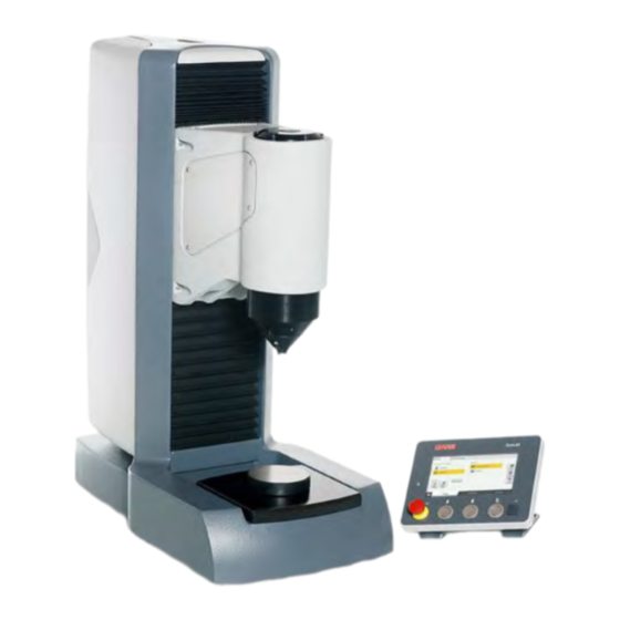
Hardness Tester Design and Functions DuraJet 10 3 Design and Functions Design, Methods and Data Interfaces Design of the unit Test unit Nose cone with indenter Control unit with touch display EMERGENCY OFF button Test anvil Machine stand The essential components of the hardness tester are the machine stand, the test unit with nose cone, the indenter and the test anvil. -
Page 33: Control Unit
Hardness Tester Design and Functions DuraJet 10 Various indenters can be supplied for the different test methods. Indenters and methods A Rockwell indenter is the standard indenter for the machine. NOTE Risk of damage Indenters should always be stored in their plastic case when not in use in order to avoid damage. - Page 34 Risk of damaging the touch screen when using sharp objects. Use your finger or a touch pen for data input. Use your finger or a touch pen for input. Use only genuine EMCO-TEST accessories. Input The three buttons Nose cone up, Nose cone down and Start testing on the control unit are active in measuring mode and in measuring mode.
- Page 35 Hardness Tester Design and Functions DuraJet 10 Safety equipment WARNING Risk of crushing by the nose cone. Severe injuries. In an emergency, press the EMERGENCY OFF button to stop the unit immediately. Never modify the safety equipment of the unit without authorization. An EMERGENCY OFF button (1) sits on the left side of the control unit as a safety device.
-
Page 36: Basic Operation
Hardness Tester Basic Operation DuraJet 10 4 Basic Operation Switching the Machine On and Off Use the main switch to turn the machine on. Switching the tester on The white LED indicator lamp is ON and the software starts. If necessary, release the EMERGENCY-OFF button on the control unit by turning it ... - Page 37 Hardness Tester Basic Operation DuraJet 10 You can enter or change numbers with the numeric keyboard. cancels the entry deletes the character to the left moves one character to the left moves one character to the right completes the entry Alphanumeric keyboard You can enter or edit text with the alphanumeric keyboard.
-
Page 38: Symbols And Buttons
Hardness Tester Basic Operation DuraJet 10 Symbols and Buttons Cancel Buttons - general Apply button Edit Scroll in list (alternatively swyping is possible) Clear input Emergency OFF is active, no operation or movement of the Icons - general machine possible. Shows that selections are active in a menu (tab page) Opens the main menu Buttons - menu... - Page 39 Hardness Tester Basic Operation DuraJet 10 Test data management "Standard". All data items are archived in Buttons - sample a standard list. Test data management "Grouped". The test data items are stored in a user-defined list. Creates a new test data group / opens the "New test data group" menu To load an existing test data group / opens a list of all existing groups.
- Page 40 Hardness Tester Basic Operation DuraJet 10 Adapting the list: Opens the menu to adjust the columns that are to be displayed. List output: Opens the menu to output the list as csv file or pdf report at the selected drive (define the drive at settings), at a connected USB flash drive or to print it on a connected printer.
- Page 41 Hardness Tester Basic Operation DuraJet 10 The buttons take you to the following menus: Menu types Measuring sequence menu Main menu Archive menu...
-
Page 42: Test Sequence
Hardness Tester Basic Operation DuraJet 10 Settings menu Test Sequence The "Test sequence" chapter describes a typical simple measurement. The "Enhanced operation" chapter gives a further description of the setting options. Start testing In the Sample menu, select the Standard option from test data management. ... - Page 43 Hardness Tester Basic Operation DuraJet 10 Select the Conversion menu. Conversion Select the Conversion table e.g. EN ISO 18265. Select the Material e.g. B2 heat-treated steel. Select the Method e.g. HRC. Conversion is selected. Select the Limits menu. ...
- Page 44 Hardness Tester Basic Operation DuraJet 10 The specified component corrections depend on the selected method. Component 1. Select the Component correction menu. correction 2. Actuate the slide switch at Component correction. 3. Select the shape Convex cylindrical or Convex spheric. ...
- Page 45 Hardness Tester Basic Operation DuraJet 10 Press the Nose cone down button (4) until the workpiece is clamped and the test unit stops automatically. Touch screen USB connection "Start Testing" button "Nose Cone Down" button "Nose Cone Up" button EMERGENCY OFF button LED indicator lamp Select the Start measurement...
- Page 46 Hardness Tester Basic Operation DuraJet 10 Measurement starts automatically if the Auto Start function is activated after clamping! The function can be found at Settings. 4-11...
-
Page 47: Testing Without The Nose Cone
Hardness Tester Basic Operation DuraJet 10 WARNING Risk of crushing by the nose cone moving downward. Severe injuries of arms and hands. Keep your hands away from the area around the moving test unit. In an emergency, press the EMERGENCY OFF button to stop the unit immediately. The software automatically analyzes and displays the impression made by the test specimen. - Page 48 Hardness Tester Basic Operation DuraJet 10 The function Auto start after clamping can not be used in a measurement without nose cone. You must therefore lower the test unit with the Nose cone down button. The test unit moves slower in this method. This protects the diamond in the indenter. 4-13...
- Page 49 Hardness Tester Basic Operation DuraJet 10 WARNING Risk of crushing by the nose cone moving downward. Severe injuries of arms and hands. Keep your hands away from the area around the moving test unit. In an emergency, press the EMERGENCY OFF button to stop the unit immediately. Approach the test unit with the Nose cone down button as closely as possible to ...
-
Page 50: Advanced Options
Hardness Tester Advanced Options DuraJet 10 5 Advanced Options This chapter introduces you to the additional options offered by the testing machine. Opening the setting menu Select the button with your finger or with the touch pen. The following screen appears on the touch screen monitor: Select the button ... -
Page 51: General Settings
Hardness Tester Advanced Options DuraJet 10 General settings The General menu has the following submenus: ▪ Configuration ▪ Times ▪ Info ▪ Modules In the Configuration submenu you can select the following settings: Configuration Configuration submenu Here you can select the basic settings, such as language, unit, Opening setup and time. - Page 52 Hardness Tester Advanced Options DuraJet 10 In the Times submenu you can set different holding times for the individual test Times procedures. Times submenu Select the test procedure, for example the Rockwell button. Preload 1, main load, and preload 2 of the test procedure are displayed. Touch the numeric value;...
- Page 53 Hardness Tester Advanced Options DuraJet 10 The Info submenu shows the following information: Info Info submenu Software version The software version is shown here. Number of The number of measurements performed with the unit is shown measurements here. Error list All system errors are listed here.
-
Page 54: User Boxes
Hardness Tester Advanced Options DuraJet 10 User boxes The User boxes menu permits up to 10 user boxes to be specified. These boxes can be filled for each measurement data group in the workflow step "Sample", and be output with the test report. Touch the button to clear the boxes. -
Page 55: Export
Hardness Tester Advanced Options DuraJet 10 Export In the Export menu you can select how the list of measured values is output. Specify delimiter and output format. Touch "Adapt export" to select the columns you want to export. Export menu Report In the Report menu you can select the information you want to show in the reports. - Page 56 Hardness Tester Advanced Options DuraJet 10 Enter the required name. Press the button to accept the name. The new name is defined and is used. You can enter a logo in your report. The logo must exist as a bitmap file in a USB flash drive in the root directory, and have the file name logo.bmp.
- Page 57 Hardness Tester Advanced Options DuraJet 10 An example of a report printout is provided below: Report printout Headlines Company logo Test method, conversion, limits Statistical trend line, bar chart, statistical analysis Result list Footer with signature field and date User fields...
-
Page 58: Network
Hardness Tester Advanced Options DuraJet 10 Network Here, you can define an available network drive that can be connected with the hardness tester. The network drive can be used for data export or for saving reports. Contact your network administrator for information. Network menu Printer A printer can either be connected directly to the hardness testes via USB or - if the... -
Page 59: Calibrating The Depth Gauge System
Hardness Tester Advanced Options DuraJet 10 Load calibration menu In the boxes Test procedure and Test method, select the test procedure and the test method for which you want to check load calibration. Place the load cell of the calibration equipment under the test unit on the test anvil ... -
Page 60: Documenting And Evaluating Results
Hardness Tester Advanced Options DuraJet 10 Remove the nose cone. Remove the indenter. In its position, install the special indenter that is usually delivered together with the depth meter (for turret option, install at position 1). Select the Depth probe menu. ... -
Page 61: Deleting Results
Hardness Tester Advanced Options DuraJet 10 Use the buttons to scroll horizontally. If you have configured a conversion, this is automatically displayed. Scroll to the left to view the results for the test method. The buttons are explained in the Chapter "Symbols and Buttons", page 4-3. Data output Touch the button to export the results. - Page 62 Hardness Tester Advanced Options DuraJet 10 The following message appears on the touch screen: Touch to delete the measured value. After you have deleted a value, all subsequent values are re-numbered. Deleting the result list Touch the button to delete the entire list of measured values. Touch the button.
-
Page 63: Cleaning And Maintenance
Hardness Tester Cleaning and Maintenance DuraJet 10 6 Cleaning and Maintenance Regular cleaning is not required. Cleaning the machine If the machine is left idle for a long period of time, ensure that it is protected from dust and dirt, and lightly oil the anvil before moving the test unit down the next time it is used. Cleaning the touch screen NOTE... -
Page 64: Startup And Retooling With Optional Accessories
Hardness Tester Startup and Retooling with Optional Accessories DuraJet 10 7 Startup and Retooling with Optional Accessories The USB port (1) sits on the front of the control unit. USB connection Various USB devices can be connected to the USB port (1): ▪... -
Page 65: External Machine Control Via Hardware Interface
The USB flash disk (USB stick) may have only a single partition. External machine control via hardware interface For this option the DuraJet G5 is equipped with an additional interface at the rear of the machine stand. Via this interface it is possible to control the DuraJet G5 via signals for "Start measurement", "Clamp test unit", "Unclamp test unit"... - Page 66 Classification low ▪ Cycle active ▪ Nose cone is clamped Scope of supply: In addition the the standard scope of supply of a DuraJet G5, the following parts are enclosed: ▪ 1x activation plug ▪ 1x blank plug Instructions for wiring and cable routing: The +24VDC power supply line (pin 1) is protected with a 3-A fuse that is installed in the DuraJet G5 unit.
- Page 67 Hardness Tester Startup and Retooling with Optional Accessories DuraJet 10 With a minimum cross-section of 1.5mm², the maximum length of the cable is 100m. Cable length of more than 100m are not permitted. The power applied at the interface connector must never be used to feed other components, sensors, or actuators.
- Page 68 Hardness Tester Startup and Retooling with Optional Accessories DuraJet 10 General safety instructions: DANGER Electric shock Prior to starting up the machine, you must make a safety compliance assessment in accordance with Machinery Directive 2006/42/EC. Comply with all the labour safety and accident prevention rules and regulations that are applicable at the location where the machine is operated.
-
Page 69: Foot Button
To be able to use the foot switch, the option "External machine control via hardware interface" must be installed in the machine. For this option the DuraJet G5 is equipped with an additional interface at the rear of the machine stand. The foot switch can be connected via this interface. - Page 70 Hardness Tester Startup and Retooling with Optional Accessories DuraJet 10 The fuse cover (1) sits between the main switch (with the green indicator lamp) and the mains connection. Turn the main switch to OFF. Unplug the power cable. Carefully pry out the fuse cover on both sides.
-
Page 71: Replacing The Test Anvil
Hardness Tester Startup and Retooling with Optional Accessories DuraJet 10 Remove the cover with the fuses. Carefully remove both fuses from their holders. Insert the replacement fuses provided into the fuse holders. Insert the fuses in their holders back into the machine. ... - Page 72 Hardness Tester Startup and Retooling with Optional Accessories DuraJet 10 Tester without the test anvil provided. Mounting a new test anvil...
- Page 73 Hardness Tester Startup and Retooling with Optional Accessories DuraJet 10 Insert the new test anvil into the space provided on the machine. 7-10...
-
Page 74: Test Methods And Indenters
Hardness Tester Startup and Retooling with Optional Accessories DuraJet 10 Unit with new test anvil and round component. Test Methods and Indenters 120° V HR15N 120° V Test methods 1/16" Ο HR30N 120° V Rockwell 120° V HR45N 120 ° V 120°... - Page 75 Hardness Tester Startup and Retooling with Optional Accessories DuraJet 10 1/8" Ο HR45W 1/8" Ο 1/4" Ο HR15X 1/4" Ο 1/4" Ο HR30X 1/4" Ο 1/2" Ο HR45X 1/4" Ο 1/4" Ο HR15Y 1/2" Ο 1/2" Ο HR30Y 1/2" Ο 1/2"...
-
Page 76: Messages And Problems
Hardness Tester Messages and Problems DuraJet 10 8 Messages and Problems If a problem occurs, send the last three entries of the error list, the software version and Error list the measured value count to your service partner. Touch OK to open the error list. ... - Page 77 Hardness Tester Messages and Problems DuraJet 10 Many error messages can be eliminated by restarting the machine. Contact your supplier if the error persists after you have restarted the machine.
- Page 78 Hardness Tester Messages and Problems DuraJet 10 In the main menu, touch Settings. Software version The following screen appears on the touch screen monitor: Touch Info. The current software version and the serial number are shown here. Use the main switch to turn the machine off. ...
- Page 79 Hardness Tester Messages and Problems DuraJet 10 The green pilot light lights up. Contact your supplier if the error persists after you restart the machine. Error description Troubleshooting Correction No information is ▪ Check the power If none of these measures are displayed on the touch supply, power cable effective, there can be a defect...
- Page 80 Hardness Tester Messages and Problems DuraJet 10 replace the indenter, refer to "Initial Startup" on page 2-9. Change the value. Entered Value outside Allowed Range! Before you start testing, move the test unit Timeout, Indenter has not down for the next measurement. Touched Sample in Time! Take the measurement again.
Need help?
Do you have a question about the DuraJet G5 and is the answer not in the manual?
Questions and answers