
Related Manuals for MKS HPS 937A Series


Summary of Contents for MKS HPS 937A Series
- Page 1 Series 937A High Vacuum Multi-Sensor System OPERATION AND MAINTENANCE MANUAL...
- Page 3 Series 937 A High Vacuum Multi-Sensor System August 1998 Part # 100009273 Rev. 4.0...
- Page 4 Baratron is a registered trademark of MKS Instruments, Inc. Elgiloy is a registered trademark of Elgiloy Co. HPS and IgniTorr are trademarks and I-MAG is a registered trademark of MKS Instruments, Inc., Vacuum Products Group Inconel is a registered trademark of Inco Alloys International, Inc.
-
Page 5: Table Of Contents
ABLE OF ONTENTS ABLE OF ONTENTS ..............1 ACKAGE ONTENTS ..............2 AFETY NFORMATION Symbols .................... 2 Symbols Used in this Manual (English) .............. 2 Symboles utilisés dans ce manuel (Français) ..........2 In dieser Betriebsanleitung vorkommende Symbole (Deutsch) ....... 3 Símbolos Usados en el Manual (Español) ............ - Page 6 Configuring a Module ............... 27 Sensor Modules ....................27 Cold Cathode ..................... 28 Pirani ......................28 Convection Pirani ..................29 Capacitance Manometer ................29 Thermocouple .................... 30 Analog Module ....................30 Pressure Units – Switches 1 and 2 ............30 Control/Combination Sensor Channels–...
- Page 7 C.C. On/C.C. Off Front Panel Push-Buttons ..........56 Cold Cathode Module Remote Connector ..........56 Analog Module .................... 56 Communications Module (optional) ............56 Using Protection and Control Set Points ..........57 Determining Protection and Control Set Points ........58 Information Update Rate ..................
- Page 8 Cleaning the Series 317 Sensor ............A.15 Testing the Series 317 Sensor ............... A.15 Preparing the 317 Sensor for Bakeout ..........A.15 Capacitance Manometer MKS Baratron® ........A.16 General ......................A.16 Installing the Baratron Capacitance Manometer .......... A.16 Connecting the Baratron™ Capacitance Manometer ........A.16 Repairing the Baratron™...
-
Page 9: Package Contents
Inspect the Series 937A System for visible evidence of damage. If it has been damaged in shipping, notify the carrier immediately. Keep all shipping materials and packaging for claim verification. Do not return the product to MKS. 937A Multi-Sensor System... -
Page 10: Safety Information
Safety Information Symbols Symbols Used in this Symboles utilisés dans Manual (English) ce manuel (Français) Definitions of CAUTION and NOTE Définition des indications messages used throughout the ATTENTION et REMARQUE manual. utilisées dans ce manuel. CAUTION: Risk of electrical ATTENTION: Risque de secousse shock. -
Page 11: In Dieser Betriebsanleitung Vorkommende Symbole (Deutsch)
Símbolos Usados en el In dieser Manual (Español) Betriebsanleitung vorkommende Symbole (Deutsch) Definition der mit VORSICHT! und Definiciones de los mensajes de HINWEIS überschriebenen PRECAUCIÓN y OBSERVACIÓN Abschnitte in dieser usados en el manual. Betriebsanleitung. VORSICHT! Stromschlaggefahr! PRECAUCIÓN: Riesgo de descarga ISO 3864, Nr. -
Page 12: Symbol Definitions
Symbol Definitions Définition des symboles Definition of Symbols apparaissant sur Found on the Unit l’appareil (Français) (English) Caution Attention refer to accompanying documents se reporter à la documentation ISO 3864, No. B.3.1 ISO 3864, No. B.3.1 Caution Attention risk of electric shock risque de secousse électrique ISO 3864, No. -
Page 13: Definitionen Der Am Gerät Angebrachten Symbole (Deutsch)
Símbolos que Aparecen Definitionen der am en la Unidad (Español) Gerät angebrachten Symbole (Deutsch) Vorsicht! Precaución Bitte Begleitdokumente lesen! Consultar los documentos adjuntos ISO 3864, Nr. B.3.1 ISO 3864, N.° B.3.1 Vorsicht! Precaución Stromschlaggefahr! Riesgo de descarga eléctrica ISO 3864, Nr. B.3.6 ISO 3864, N.°... -
Page 14: Safety Precautions
Do not substitute parts or modify instrument. Do not install substitute parts or perform any unauthorized modification to the instrument. Return the instrument to an MKS Calibration and Service Center for service and repair to ensure that all safety features are maintained. - Page 15 Do not operate in explosive environments. To avoid explosion, do not operate this product in an explosive environment unless it has been specifically certified for such operation. Service by qualified personnel only. Operating personnel must not remove instrument covers. Component replacement and internal adjustments must be made by qualified service personnel only.
- Page 16 être source d’une secousse électrique. Ne pas substituer des pièces ou modifier l’appareil. Ne pas utiliser de pièces détachées autres que celles vendues par MKS Instruments, Inc. ou modifier l’appareil sans l’autorisation préalable de MKS Instruments, Inc. Renvoyer l’appareil à un centre d’étalonnage et de dépannage MKS pour tout dépannage ou réparation afin de s’assurer que tous...
- Page 17 Ne pas utiliser dans une atmosphère explosive. Pour éviter tout risque d’explosion, ne pas utiliser l’appareil dans une atmosphère explosive à moins qu’il n’ait été approuvé pour une telle utilisation. Dépannage effectué uniquement par un personnel qualifié. L’opérateur de l’appareil ne doit pas enlever le capot de l’appareil. Le remplacement des composants et les réglages internes doivent être effectués uniquement par un personnel d’entretien qualifié.
-
Page 18: Sicherheitsvorschriften Und Vorsichtsmaßnahmen (Deutsch)
Bauen Sie in das Instrument keine Ersatzteile ein, und nehmen Sie keine eigenmächtigen Änderungen am Gerät vor! Schicken Sie das Instrument zu Wartungs- und Reparatur-zwecken an einen MKS-Kalibrierungs- und - Kundendienst ein! Dadurch wird sicher-gestellt, daß alle Sicherheitseinrichtungen voll funktionsfähig bleiben. - Page 19 Richtige Sicherung benutzen! Es ist eine Sicherung zu verwenden, deren Typ, Nennspannung und Nennstromstärke den Angaben für dieses Produkt entsprechen. Gerät nicht in explosiver Atmosphäre benutzen! Um der Gefahr einer Explosion vorzubeugen, darf dieses Gerät nicht in der Nähe explosiver Stoffe eingesetzt werden, sofern es nicht ausdrücklich für diesen Zweck zertifiziert worden ist.
-
Page 20: Procedimientos Y Precauciones De Seguridad (Español)
MKS Instruments, Inc., no asume responsabilidad alguna en caso de que el cliente haga caso omiso de estos requerimientos. Puseta a tierra del instrumento. - Page 21 Usar el fusible adecuado. Usar únicamente un fusible del tipo, clase de voltaje y de corriente adecuados, según lo que se especifica para el instrumento. Evitar su uso en entornos explosivos. Para evitar el riesgo de explosión, no usar este instrumento o en un entorno explosivo, a no ser que haya sido certificado para tal uso.
-
Page 22: Specifications
Specifications* Controller Measuring Range** 1 x 10 to 1.0 x 10 Torr 1 x 10 to 1.3 x 10 mbar 1 x 10 to 1.3 x 10 1 x 10 to 1.0 x 10 microns Operating Temperature Range 5° to 40°C (41° to 104°F) Storage Temperature Range -10°... - Page 23 Analog Outputs Buffered and Logarithmic (0.6 V/dec) outputs for each channel Two wide-range combination logarithmic outputs. Zout=100 ohms Number of Channels Front Panel Controls Power on-off switch, 7-position rotary switch for function selection, 5-position rotary switch for sensor selection, 2 push-button switches for adjustments &...
- Page 24 Computer Interface (Optional) Serial – RS-232 and RS-485 2400, 4800, 9600, 19200 bit rate selectable Electronic Casing Aluminum Dimensions 9½" x 12¼" x 3½" (W x D x H) (241 mm x 311 mm x 88 mm) Size ½ rack, 2U high Typical Weight 8.0 lb (3.6 kg) CE Certification...
-
Page 25: Sensors
Series 315 Pirani Series 345 Pirani Convection Pirani (CEP) Series 317 Convection Pirani ® MKS Baratron 622A, 626A, or 722A Capacitance Manometer; ±15 V at 35 mA externally-powered; unheated;0 to 10 V range transducer, 10 V corresponds to either 1, 10,... - Page 26 Relay Set Point Range 2.0 x 10 to 9.5 x 10 Torr 2.7 x 10 to 1.2 x 10 mbar 2.7 x 10 to 1.2 x 10 2.0 x 10 to 9.5 x 10 microns Pirani 2.0 x 10 to 9.5 x 10 Torr 2.7 x 10 to 1.2 x 10...
- Page 27 Repeatability CC, Pirani, CEP , TC 5% of indicated pressure at constant temperature 2% of indicated pressure at constant temperature Calibration Gas CC, Pirani, CEP , TC Air/nitrogen Any (gas independent) Installation Orientation CC, TC, CM,Pirani Any (port down suggested) Body horizontal only Materials Exposed to Vacuum Series 421 –...
- Page 28 Operating Temperature Range Series 421 - 0° to 70°C (32° to158°F)Special available that operates up to 200°C. Series 423 - 0° to 70°C (32° to158°F) Pirani 0° to 50°C (32° to 122°F) 10° to 50°C (50° to 122°F) 0° to 50°C (32° to 122°F) 0°...
- Page 29 Length* Series 421 – 6.3 in. (160 mm) Series 423 – 3.4 in. (86 mm) Pirani 4.4 in. (112 mm) 4.4 in. (112 mm) Type 122 and 622 - 4.9 in. (124 mm) Type 626 - 4.8 in. (121 mm) Type 722 -3.9 in.
-
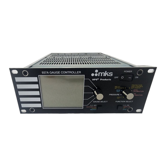
Page 30: Feature And Control Locations
Feature and Control Locations Front Panel 12 13 16 17 18 Rear Panel 937A Multi-Sensor System... - Page 31 Display Label Liquid Crystal Display Gauge Select Rotary Switch Power On-Off Switch Function Select Rotary Switch C.C. On/User Cal/Up/Zero Push-button C.C. Off/Factory Cal/Down/Beeper Push-button Power Supply Module Male, 15-pin "D" Accessory Connector AC Power Inlet, IEC 320 Slot for optional Communications Module Analog Module UCAL Enable/Disable Switch Female, 25-pin "D"...
-
Page 32: Typical Applications For The Series 937A
Typical Applications for the Series 937A Measurement of high vacuum chamber pressures Control of high vacuum systems and process sequencing using relay set points Sensing abnormal pressure and taking appropriate security measures using relay set points Controlling system pressure using the analog output as input to an automatic pressure controller Starting or stopping system processes with relay set points Measuring pressures of backfilled gases... -
Page 33: Hps™ Products Series 937A Multi-Sensor High
HPS™ Products Series 937A Multi-Sensor High Vacuum System HPS™ P 937A Multi-Sensor High Vacuum System RODUCTS ERIES uses the technologies of the cold cathode, standard Pirani, convection Pirani, and thermocouple sensors and the capacitance manometer together to measure pressures from as high as 10,000 Torr down to ultra high vacuum. The System operates as many as five sensors simultaneously. -
Page 34: Set Points
Set Points Control your system with five independently adjustable relay set points. They may be set or disabled from either the front panel or the optional communications module. The set points are nonvolatile, remaining unchanged after powering down or during a power failure. The Controller also includes additional protection and control set points to turn a cold cathode sensor off at higher pressures, extending the operating time before maintenance is required. -
Page 35: Setting Up The Series 937A Controller
Setting Up the Series 937A Controller This section covers switch and jumper settings on the various Controller modules — sensor, analog, power supply, and optional communications modules. Controller power supply and mounting is also covered. For information on connecting sensors and their cables to the Series 937A Controller, see Appendix A. -
Page 36: Cold Cathode
Enable) has either only the first of these jumpers or neither. To use older modules in a Series 937A Controller or new modules in a Series 937 or 929 controller, contact HPS™ Products Applications Engineering at MKS Vacuum Products Group to request the application note on Configuration of Cold Cathode Modules for 929/A/937/A Controllers . -
Page 37: Convection Pirani
Convection Pirani Jumper A Convection Pirani sensor module can be installed in Slots A , B , or both. Either a single-channel or a dual-channel module is available. A 3-pin header W1 with a jumper is near the end of the module opposite the rear panel of the Controller. -
Page 38: Thermocouple
Thermocouple A thermocouple module can be installed in Slots A , B , or both. Either a single-channel or a dual-channel module is available. The figure to the right shows the thermocouple module's "D" connector. A key is placed in contact #8. This key prevents connection of a Pirani, capacitance manometer, or Convection Pirani sensor cable to a Keyed "D"... -
Page 39: Line Frequency - Switch 5
Line Frequency – Switch 5 Set this switch to the line frequency in use to minimize noise pickup. This 60 Hz switch does not affect the power supply. 50 Hz Factory preset line frequency: As requested Cold Cathode Sensor Delay – Switch 6 When cold cathode sensors are turned on at high vacuum, the discharge current does not start immediately. - Page 40 RS-485 communications at high speed and over long wires may require both Bit Rate and Parity Selection ends of the cable to be terminated with its characteristic impedance. Holes SWI Seting marked R1 on the module are for a termination resistor if needed. For twisted Rate Parity Switch...
-
Page 41: Power Supply Module
A 9-pin "D" connector is used for RS-232 and RS-485 serial interfaces. Three pins are used for the RS-232 interface using the standard PC-AT connections for a DTE (data terminal equipment) device. Two more pins are used for the RS-485 interface. A second pass-through connector for RS-485 facilitates connection of multiple devices on the same bus. -
Page 42: Panel Labels
A change of pressure units, module type, or capacitance manometer head range may invalidate user calibration and setpoint values. If the set point value is within the acceptable range, it will remain the same numeric value. If it is not within the acceptable range, then the setpoint will be disabled and reset to 0.0 . -
Page 43: Ac Power Cord
Mounting the Series 937A controller into a 19" rack (HPS Part 100005651) Attach the faceplate (3.5"x5.5") to each side of the 937A front panel using the four 10-32 screws provided. Secure the screws with the nuts included in the kit. Secure this assembly to the rack using the ¼"... -
Page 44: Operating The Series 937A Controller
Operating the Series 937A Controller Please note, the characters on the Controller digital display vary slightly from those shown in this manual (e.g., P I R is actually and T C is actually If REMOTE indicator is displayed,operation from the Front Panel has been disabled. - Page 45 CC, A1, A2, B1, or B2 Channel - indicates a sensor module is inserted in this slot. A2 and B2 only display if a dual sensor module is installed. These indicators are displayed in any Function Select mode . User Zero (Vacuum) or Atmospheric Calibration - indicates the factory default calibration setting for zero, atmosphere, or both have been overridden.
-
Page 46: Using The Front Panel Controls
CONTROL 1 (Slot CC) or CONTROL 2 (Slot A) with C T L Control Sensor Status - indicates that the control sensor's pressure is above the control set point and has turned the cold cathode sensor's high voltage off. REMOTE Controller Functions Disabled Locally - indicates all functions on the Controller's front panel are disabled and are accessible only from the optional communications interface. -
Page 47: Using Function Select
Using Function Select Display Test Mode A display test is automatically performed for the first few seconds when starting the Controller. To see all display segments at any other time, turn the Function Select rotary knob to Display Test . This function is also used to review Controller setup. -
Page 48: Cold Cathode Non-Standard Configuration Codes
The indicator for the units of pressure (TORR, mBAR, PASCAL, or MICRON) also appears. An indicator U appears next to any sensor operating with a zero or atmosphere calibration value set by the user with the Zero or ATM Calibration modes (i.e., not factory-set values). -
Page 49: Setup Review Screen 2
Condition Remedy Code Module is configured correctly The high voltage supply of this CC 8 Review Steps module cannot be properly 1-3 above Reject Module controled CC (may appear with I) If the input is not The rear panel connector of this needed, this code may module provides direct control of Limited Rear Panel HV... -
Page 50: Setup Review Screen 4
The auto-zero indicator A U T appears on the top display line. The auto-zero status of each head appears on its channel's display line. Auto-zero enabled O F F Auto-zero disabled Setup Review Screen 4 This screen shows the channel and type of control/combination sensor selected for a cold cathode sensor in Slots CC or A . -
Page 51: Setup Review Screen 7
Setup Review Screen 7 The last screen shows line frequency selected. 5 0 H 50 Hz 6 0 H 60 Hz The codes which appear in the bottom lines of the display are the revisions of the Series 937A system Pressure units software and communications software (if installed) Pressure Mode... -
Page 52: Cold Cathode Sensor High Voltage
Improper connection, Broken sensor wire - A Pirani, thermocouple, or Convection Pirani sensor is improperly connected or its sensor wire is broken. Calibration error - A capacitance manometer is indicating pressure below 0 Torr. Cold Cathode Sensor High Voltage The high voltage of cold cathode sensors can be turned on and off in Pressure mode. -
Page 53: Leak Test Mode
Leak Test Mode Leak Test Mode will work with all sensors except the capacitance manometer, which is not gas dependent. If the Gauge Select switch is set to a capacitance manometer or a channel with no module installed, N O will appear in the display line of the selected channel. -
Page 54: Relay Set Points Mode
Relay Set Points Mode The Relay Set Points mode is used to review and set the pressure at which the set point relays switch. Five setpoint relays are available; one for Slot CC and two each for Slots A 15 Pin Accessory Connector and B . -
Page 55: Disabling A Relay Set Point
A new set point takes effect and is saved in nonvolatile memory when either the Function Select or the Gauge Select switch is turned to another position. The new set point is not saved if the Controller is turned off before turning one of these switches. -
Page 56: Protection And Control Set Points Mode
Protection and Control Set Points Mode This section describes how to use the Protection and Control Set Points mode to adjust these set points with cold cathode sensors. See Cold Cathode Operation, page 55, for additional information. Protection Set Point Setting a Protection Set Point To select a protection set point, Turn the Function Select switch to Protection and Control Set Points . -
Page 57: Protection And Control Set Point Display Messages
In either case, the control set point value is always displayed on the line for the channel that is configured as the control sensor. When the selected channel is not the same as the configured control channel, B1 or B2 will appear on the selected display line of Slot B to indicate which channel is the configured control channel. -
Page 58: Disabling A Protection Or Control Set Point
Disabling a Protection or Control Set Point Set the Gauge Select switch to the desired set point. Hold the Down push button until the set point is at the bottom of its range. Release and depress it once more. The set point will decrement to 0.0. -
Page 59: Zero Calibration Mode
User Calibration establishes the current reading from the sensor as the new calibration value. The calibration value is stored in non- volatile memory and is restored when the Controller is turned on. When user calibration is in effect for either zero or atmosphere, a U indicator will appear next to the channels display line. -
Page 60: Capacitance Manometer Auto-Zero Feature
A special calibration algorithm in the 937A allows independent zero and atmosphere calibration adjustments for Pirani, Convection Pirani and thermocouple sensors. Capacitance Manometer Auto-Zero Feature The auto-zero feature continuously resets the zero of a capacitance manometer when the cold cathode sensor in Slot CC indicates system pressure is low enough. -
Page 61: Atm Calibration Mode
ATM Calibration Mode Atmosphere calibration is provided for the Pirani, Convection Pirani and thermocouple sensors. Please refer to the next section for calibration of the Convection Pirani sensor. To perform Factory Calbration Turn the Function Select switch to ATM Calibration. Set the Gauge Select switch to the desired channel. -
Page 62: Calibrating The Convection Pirani Sensor For Atmosphere
Calibrating the Convection Pirani Sensor for Atmosphere Since the Series 317 Convection Pirani sensor gives numerical pressure readings at atmospheric pressure, the local atmospheric pressure must be determined in order to correctly calibrate the sensor. Atmospheric pressure depends on altitude and to a lesser degree, weather systems and climate control (HVAC systems). -
Page 63: Cold Cathode Operation
Vent the system to atmospheric pressure or back fill it with nitrogen using a reference sensor to avoid overpressure. Allow the sensor to stabilize for at least 10 minutes. Turn Function Select switch to ATM Calibration . Potentiometer for channel 1 Set the Gauge Select switch to the channel to be calibrated. -
Page 64: C.c. On/C.c. Off Front Panel Push-Buttons
The high voltage for the cold cathode sensor can be controlled by six methods. CC On/Off push buttons on the front panel The Remote connector on the rear panel of the Cold Cathode Module. The connector on the rear panel of the Analog Module (Slot CC only). Commands sent to the Series 937A Communications Module Protection Set Point (sensor automatically controlled by 937A) Control Set Point(sensor automatically controlled by 937A) -
Page 65: Using Protection And Control Set Points
If a cold cathode sensor has been disabled using the XCCn command, the ECCn command must be used to re-enable the sensor. No other method can override the XCCn command. In the event that the cold cathode can not be re-enabled from the Communications Module, the power switch on the Series 937A controller must be turned off (for at least 5 seconds) and then turned on again. -
Page 66: Determining Protection And Control Set Points
Choosing between the protection and control set points depends upon several factors, including the need for automatic start-up, and the possibility of the pressure rising into the rollback range. The reading from a cold cathode sensor will "roll back", or indicate a false low pressure, when operated above 5.0x10 Torr. -
Page 67: Information Update Rate
When using a control set point near the lower limit, check the zero calibration and correct if necessary (see page 49). If a control set point is used, disable the protection set point or set it to a higher value than the control set point. Otherwise, the protection set point will override the control set point, preventing automatic start-up of the cold cathode sensor when the pressure falls back below either set point. -
Page 68: Controller Analog Output
Controller Analog Output Description The chart identifies the pins of the female, 25-pin "D" connector on the Analog Module. analog output, combination, channel CC analog output, buffered, channel CC analog output, buffered, channel A1 Buffered and logarithmically scaled analog outputs are analog output, buffered, channel A2 available from each sensor. -
Page 69: Logarithmic Output
Logarithmic Output Logarithmic output is scaled for 0.6 V per decade of pressure. Only one curve is needed to determine the pressure from the logarithmic output for any sensor (see Appendix C). For example, at 1.0 x 10 Torr, a Pirani sensor will have the same logarithmic voltage output value, 5.4 V, as a cold cathode sensor. -
Page 70: Combination Logarithmic Output
Combination Logarithmic Output A combination sensor is a control sensor with a range that overlaps the range of the cold cathode sensor. This excludes the 10 and 100 Torr capacitance manometer heads. Refer to page 30 for the selection of control/ combination sensors. A combination output combines the measurement ranges of a cold cathode sensor and its combination sensor. -
Page 71: Error Messages
Error Messages The Series 937A Controller is designed to be maintenance free with normal operation. Three types of Controller errors may be detected when the Controller is turned on – ROM checksum, EEPROM correction data, and module or sensor setup. These errors are different from sensor error messages. -
Page 72: Setup Error
Press the Up push-button to cancel this message. The Controller will now work normally, except the correction factors are lost and can no longer correct the affected channel's A/D readings. This can cause a reading error up to +100%/-50% at pressures where sensor curves are relatively flat (near the top or bottom of a pressure range for most sensors). -
Page 73: Quick Reference Tables
Quick Reference Tables Table I Front Panel Operation Effect of Gauge Select switch and push-buttons in the seven primary functions. Push Front Panel Push-button to Set Gauge Numerical Left Right Select Switch to Display Shows Display Reverse thru Forward thru Setup review Any sensor Test... -
Page 74: Relay Setpoints
Table II Setpoint Values Pressure values below are specified in Torr. Numerical values of the limits will change depending upon the units selected; however, the acutal pressure of the limits will be the same. Values are not adjusted when units are changed. They will retain the same numerical value in the new units, which is not the same pressure. -
Page 75: Spare Parts And Accessories
Spare Parts and Accessories Part # Accessory Connector Kit 100005087 Cable for Capacitance Manometer, Type 122A/622A 10 ft (3.0 m) 100007550 25 ft (7.6 m) 100007551 50 ft (15.2 m) 100007552 Custom to 50 ft (15.2 m) 100007553 Cable for Capacitance Manometer, Type 122B/626A 10 ft (3.0 m) 100007555 25 ft (7.6 m) - Page 76 Internal Rebuild Kit Series 421 100006734 Spanner Wrench 100005279 ® Series 423 I-MAG 100002353 Module, Communications RS-232/RS-485 100009183 Module, Sensor Cold Cathode 100009428 Dual Pirani 100005961 Single Pirani 100007033 Dual Capacitance Manometer 100007321 Single Capacitance Manometer 100006037 Dual Thermocouple 100006034 Single Thermocouple 100007034 Dual Convection...
- Page 77 HPS™ Products Series 937A Combination 100009273 Vacuum Sensor System User's Manual Please call the HPS™ Products Customer Service Department of MKS Vacuum Products Group at 1-303-449-9861 or 1-800-345-1967 to order any of these parts or to receive catalogs for other MKS products.
-
Page 78: Product Warranty
PERIOD. NO WARRANTIES, EXPRESS OR IMPLIED, WILL APPLY AFTER THIS PERIOD. Warranty Service The obligations of MKS under this warranty shall be at its option: (1) to repair, replace, or adjust the product so that it meets applicable product specifications published by MKS or (2) to refund the purchase price. -
Page 79: Notes
Notes 937A Multi-Sensor System... -
Page 80: Appendix A: Installing A Series 937A Sensor
The MKS inverted magnetron design includes an isolated collector, making low pressure measurement less susceptible to contamination and allowing a wider range of pressure measurement. The MKS IgniTorr™, an optional cold cathode starting device initiates the ionization process in cold cathode sensors, assuring UHV pressure readings in seconds (see Spare Parts and Accessories, p. -
Page 81: Managing Contamination In A Cold Cathode Sensor
Managing Contamination in a Cold Cathode Sensor Do not operate at pressures above 10 Torr for extended periods as this will increase the likelihood of contamination. If pressure readings appear to be erratic, the Sensor tube may be contaminated. Inspect it visually. If contamination is visible, you should replace the internal components with an Internal Rebuild Kit (see Accessories, p.67). -
Page 82: Cleaning The I-Mag Sensor
Remove the magnet Using the smooth-jaw, needle-nose pliers, firmly grab the compression spring at the tip closest to the flange. Pull on the compression spring while rotating to free it from the formed groove of the sensor body . Continue to pull until the compression spring is completely free. - Page 83 Series 423 I-MAG ® Sensor, exploded view 937A Multi-Sensor System...
-
Page 84: Assembling The I-Mag Sensor
Assembling the I-MAG Sensor Wear gloves and assemble with clean tools. Roll the sensor body on a flat surface and, looking down the port, check the anode for any radial runout motion. It should be straight and centered with the sensor body for proper operation. -
Page 85: Preparing The Sensor For Bakeout
The I-MAG Sensor is ready for installation. If it is not immediately installed, cover the flange with clean, vacuum grade aluminum foil and cap with a flange protector. Preparing the Sensor for Bakeout To prepare the sensor for bakeout up to 400°C, remove the sensor cable and magnet assembly as described in "Disassembling the I-MAG sensor". - Page 86 Backshell Subassembly Internal Subassembly Body Subassembly Series 421 Cold Cathode Sensor, exploded view of backshell, internal, and body subassemblies 937A Multi-Sensor System...
-
Page 87: Cleaning The Series 421 Sensor
To disassemble the Sensor, remove the backshell subassembly as follows (Steps 1 through 4 are not necessary when replacing internal parts): Remove the two 4-40 x ¼" Phillips head SEMS screws and slide the backshell off the sensor. Remove the two 4-40 x ¼" button head screws Use needle nose pliers to pull the #22 contact carefully off of the ion current feedthrough... -
Page 88: Assembling The Series 421 Sensor
Assembling the Series 421 Sensor To reassemble, reverse the order used during disassembly. Note the following tightening procedure of the guard bolt . The bolt has a "-40 thread which is delicate. Finger tighten the guard bolt to compress the spring washer and then back off one turn. -
Page 89: Preventing Contamination In A Pirani Sensor
Preventing Contamination in a Pirani Sensor Locate and orient a Pirani sensor to avoid contamination which might affect the tube's element. For example, if a sensor is installed directly above a roughing pump in the system, oil vapor could contaminate the tube's filament wire and cause the calibration to shift. - Page 90 The sensor cable is connected to the Controller with the 9-pin "D" connector as shown above. This connector is equipped with integral strain relief. Screw the strain reliefs into the mating standoffs on the rear of the Controller for good contact and to avoid excess stress on the connectors. Description bridge drive, + bridge drive, -...
-
Page 91: Cleaning The Series 315/345 Sensor
Cleaning the Series 315/345 Sensor Roughing pump oils and other fluids condensing or decomposing on the heated filament can contaminate the Sensor. This changes the emissivity of the filament, which in turn can cause the calibration to change, especially at low pressure. It is not advisable to clean the Sensor. -
Page 92: Connecting The Series 317 Sensor
Mount the Sensor with the vacuum port facing downward to reduce particulates and liquids falling or flowing into it. The Sensor has been calibrated in this position. Connecting the Series 317 Sensor To fit a KF 16 port to a KF 10 port, use an HPS adaptive centering ring (HPS™... - Page 93 A Convection Pirani sensor is connected to the Controller's convection sensor module with a multiconductor shielded Description cable. It has a 9-pin "D" connector at each end as shown here. bridge drive, + This connector is equipped with integral strain relief. Screw the bridge drive, - strain reliefs into the mating standoffs on the rear of the chassis ground...
-
Page 94: Cleaning The Series 317 Sensor
Cleaning the Series 317 Sensor Roughing pump oils and other fluids condensing or decomposing on the heated filament can contaminate the Sensor. This changes the emissivity of the filament, which in turn can cause the calibration to change, especially at low pressure. -
Page 95: Capacitance Manometer Mks Baratron
Baratrons are widely known for their accuracy and reliability and are available in full scale ranges from 1 to 1000 Torr, each with a 3-decade range. See an MKS Baratron instruction manual for complete information on using these capacitance manometers. Installing the Baratron Capacitance Manometer... -
Page 96: Repairing The Baratron™ Capacitance Manometer
Baratron Type 626A shielded cable with 15-pin "D"connector Repairing the Baratron™ Capacitance Manometer Repair by the user is not recommended since replacement or movement of PC board components may require complete calibration of the unit. Return to MKS for repair. 937A Multi-Sensor System A.17... -
Page 97: Thermocouple Sensor
Thermocouple Sensor Teledyne-Hastings DV-6M General Thermocouple sensors, like Pirani sensors, measure vacuum through thermal conductivity. A thermocouple is used to measure temperature of a heated wire. The temperature of the wire is directly related to the gas pressure. Thermocouple sensors measure pressure from 1.0 x 10 to 1 Torr. -
Page 98: Cleaning The Dv-6M Sensor
Description thermocouple AC drive thermocouple AC return signal + chassis ground Keyed "D" connector for thermocouple DV-6M thermocouple sensor shielded cable with 9-pin "D" connector Cleaning the DV-6M Sensor Roughing pump oils and other fluids condensing or decomposing on the heated filament can contaminate the Sensor. -
Page 99: Appendix B: Leak Testing With The Series 937A
Appendix B: Leak Testing with the Series 937A While the Series 937A Controller is not intended to replace mass spectrometer leak detectors, it offers a simple and inexpensive method for locating leaks in high vacuum systems. Under ideal conditions, a Pirani sensor can detect leaks as small as 1x10 Torr l/s and the cold cathode sensor can be used to detect leaks as small as 1x10... - Page 100 Place the pump away from the suspected leak source and place the sensor between the leak and the pump to reduce the sensor response time. Vacuum tubing between the suspected leak and the sensor should be as short and wide as possible to shorten the time required for the probe gas to reach the sensor.
-
Page 101: Appendix C: 937A Sensor Output Vs. Pressure Curves
Appendix C: 937A Sensor Output vs. Pressure Curves When using the graphs, remember that the pressure scale is always logarithmic, and the voltage scale is linear for all sensors except the capacitance manometer. Equal increments of distance along a logarithmic scale does not correspond to equal pressure or voltage changes. -
Page 102: Buffered Analog Output Pirani (Series 315 And 345)
Buffered Analog Output Pirani (Series 315 and 345) Pressure (Torr) 937A Multi-Sensor System C. 2... -
Page 103: Buffered Analog Output Convection Pirani (Series 317)
Buffered Analog Output Convection Pirani (Series 317) Pressure (Torr) 937A Multi-Sensor System... -
Page 104: Buffered Analog Output Capacitance Manometer
Buffered Analog Output Capacitance Manometer Head Full-Scale Range (Torr) 1000 10,000 0.01 Pressure (Torr) 937A Multi-Sensor System C. 4... -
Page 105: Buffered Analog Output Thermocouple (Dv-6M)
Buffered Analog Output Thermocouple (DV-6M) Pressure (Torr) 937A Multi-Sensor System... -
Page 106: Logarithmic And Combination Output All Sensors
Logarithmic and Combination Output All Sensors Output Voltage (VDC) 937A Multi-Sensor System C. 6...
Need help?
Do you have a question about the HPS 937A Series and is the answer not in the manual?
Questions and answers