
Related Manuals for Alfa Laval SRU series


Summary of Contents for Alfa Laval SRU series
- Page 1 Instruction Manual Rotary Lobe Pumps - SRU Range ESE00693-EN14 2017-09 Original manual...
-
Page 3: Table Of Contents
Table of contents The information herein is correct at the time of issue but may be subject to change without prior notice 1. EC Declaration of Conformity ............... 2. General information ................... 2.1. General information ................3. Safety ....................3.1. Important information ................3.2. -
Page 4: Ec Declaration Of Conformity
1 EC Declaration of Conformity Revision of Declaration of Conformity 2009-12-29 The Designated Company Alfa Laval Eastbourne, Alfa Laval Ltd Company Name Birch Road, Eastbourne, East Sussex BN23 6PQ Address +44 (0) 1323 412555 Phone No. hereby declare that Pump Designation SRU1, SRU2, SRU3, SRU4. -
Page 5: General Information
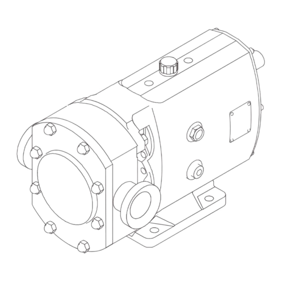
2 General information 2.1 General information The SRU pump supplied is a positive displacement rotary lobe pump; it may be supplied with or without a drive unit (see drawing). The drawing shown indicates various parts of the pump unit. The SRU range has a universal gearbox design which enables the flexibility of mounting pumps with the inlet and outlet ports in either a vertical or horizontal plane. -
Page 6: Safety
3 Safety Unsafe practices and other important information are emphasized in this manual. Warnings are emphasized by means of special signs. 3.1 Important information Always read the manual before using the pump! WARNING Indicates that special procedures must be followed to avoid serious personal injury. CAUTION Indicates that special procedures must be followed to avoid damage to the pump. -
Page 7: Safety Precautions
3 Safety Unsafe practices and other important information are emphasized in this manual. Warnings are emphasized by means of special signs. 3.3 Safety precautions Installation: Always read the technical data thoroughly. (See chapter 6 Technical data) Never start in the wrong direction of rotation with liquid in the pump. Never put your hands or fingers inside the port connections or anywhere close to rotating parts. -
Page 8: Installation
4 Installation 4.1 Unpacking, handling and storage Step 1 Refer to the pump weights guide (6 Technical data) before selecting and using any lifting gear. The drawings show how the pump should be lifted. Ensure that lifting equipment is correctly rated and used within these limits. Pump with drive unit Bareshaft pump Step 2... -
Page 9: System Design And Installation
4 Installation To ensure optimum operation it is important that any pump unit is installed correctly. When designing a pumping system the following should be taken into consideration. 4.2 System design and installation Design: Discharge line - Confirm the Net Positive Suction Head (NPSH) available from the system exceeds the NPSH required by the pump, as this is crucial for ensuring the smooth operation of the pump and preventing cavitation. - Page 10 4 Installation To ensure optimum operation it is important that any pump unit is installed correctly. When designing a pumping system the following should be taken into consideration. Table of Maximum Forces and Moments Forces Moments Pump Model Units Units SRU1 lbft SRU2...
- Page 11 4 Installation To ensure optimum operation it is important that any pump unit is installed correctly. When designing a pumping system the following should be taken into consideration. Pump Lubrication: The pump will not be supplied pre-filled with oil therefore this table must be used to select recommended oil. Oil changing: Oil level must be checked with the pump static.
- Page 12 4 Installation To ensure optimum operation it is important that any pump unit is installed correctly. When designing a pumping system the following should be taken into consideration. Coupling alignment: Before the pump unit is installed is it important to ensure that the mounting surface is flat to avoid distortion of the baseplate, which may cause pump/motor shaft misalignment and pump/motor unit damage.
-
Page 13: Flushing Seal Arrangement And Pre-Start Up Checks
4 Installation This page is not applicable for ATEX applications. For ATEX application see ATEX addendum 4.3 Flushing seal arrangement and pre-start up checks Step 1 A flushed seal arrangement is fitted in order to cool or clean the seal area. It is important that: - The flush is correctly connected (see below). -
Page 14: Recycling Information
- At end of use, the equipment shall be recycled according to relevant, local regulations. Beside the equipment itself, any hazardous residues from the process liquid must be considered and dealt with in a proper manner. When in doubt, or in the absence of local regulations, please contact the local Alfa Laval sales company. -
Page 15: Maintenance
5 Maintenance 5.1 Cleaning in place (CIP) The pump can be manually cleaned or cleaned in place (CIP). The following is an example of a typical CIP procedure. However specific advice for each application should be sought from the pump supplier. Typical CIP procedure 1. -
Page 16: Maintenance Schedule
5 Maintenance 5.2 Maintenance schedule It is advisable to install pressure gauges on both sides of the pump so that any problems within the pump/pipework can be monitored. Maintenance schedule Your weekly schedule should include: - Checking the oil level in the gearcase with the pump stationary. - Checking the seals for leakage. -
Page 17: Dismantling
5 Maintenance 5.3 Dismantling Step 1 Before dismantling the pump refer to safety precautions. See exploded view drawings (chapter 7 Parts list). Removing rotorcase cover 1. Remove rotorcase cover nuts (13) and cover (12). Step 2 Removing rotors 1. Insert a plastic/wooden block between the two rotors (17) to stop them turning. - Page 18 5 Maintenance Step 5 Removing seal retainers 1. Remove screws (15). 2. Then remove seal retainers (14) - as a liquid sealant has been used a lever may be required to remove retainers. 3. The lip seals (16) can be removed using a screwdriver/ lever once the seal retainers are removed.
- Page 19 5 Maintenance Step 9 Bearing removal 1. Hold the shafts (24 and 25) in a vice using soft jaws to protect the areas where the seals will be located. 2. Remove the bearing nuts (30) with a ‘sharp tap’ on a ‘C’ spanner.
-
Page 20: Assembly
5 Maintenance 5.4 Assembly 5.4.1 Fitting bearings to shafts Take care not to damage shaft surfaces, in particular where the seals will be located. Ensure all fastenings are tightened to torque settings as shown in 6 Technical data. On series 1, 2 and 3 pumps, bearings do not require heating. For series 4, 5 and 6 pumps, heat the bearing inner cones to 110°C (230°F). - Page 21 5 Maintenance 5.4.2 Fitting Shaft Assemblies Step 1 Replace the shaft abutment spacer (27). - For vertically ported pumps this is placed in the right hand bearing bore when viewed on the front face of the gearcase. - For horizontally ported pumps the shaft abutment spacer is placed in the top bearing bore. Step 2 Identify drive and auxillary shaft positions according to gearcase cover (5) orientation.
- Page 22 5 Maintenance 5.4.4 Checking rotor abutment alignment Step 1 Incorrect setting of rotor alignment will damage the pump. Fit rotors onto shafts (24 and 25) and tighten rotor retention nuts (22). Step 2 1. Using a depth micrometer ensure axial alignment is within tolerance of 0.012mm (0.0005 in).
- Page 23 5 Maintenance 5.4.6 Adjusting rotor timing Step 1 If the rotor timing requires adjustment (and assuming the pump has not yet been re-built), it is important to establish the cause for the rotors mistiming before proceeding. To allow timing adjustment ensure that one shaft is able to rotate within the torque locking assembly/element. The other torque locking assembly/element should be tightened to the recommended torque.
- Page 24 5 Maintenance 5.4.7 Fitting gearcase cover Step 1 Clean the gearcase cover bore and remove all gasket material from the face. Press a new lip seal (7) into the cover (5). For temperatures greater than 130°C (266°F) FPM lip seals are fitted. Step 2 Apply liquid gasket to the face of the cover where it mates with the gearcase.
- Page 25 5 Maintenance 5.4.9 Fitting primary seals Step 1 Refer to section 5.5 for seal fitting instructions. 5.4.10 Fitting rotors Step 1 1. Fit new rotor O rings (18). 2. Fit rotors (17) onto the shafts (24 and 25) with both dimpled rotor master lobes in the 6 -12 o’clock position (horizontally ported pumps) or 3-9 o’clock position (vertically ported pumps).
- Page 26 5 Maintenance 5.4.11 Fitting rotorcase cover Step 1 1. Lightly smear new O-ring (11) in grease and fit to rotorcase cover (12). 2. Fit rotorcase cover onto rotorcase (9) and tighten rotorcase cover nuts (13). 3. Refer to pump start up checks prior to operation.
-
Page 27: Primary Seals Removal And Fitting
5 Maintenance This page is not applicable for ATEX applications. For ATEX application see ATEX addendum 5.5 Primary seals removal and fitting 5.5.1 R90 Single mechanical seal Mechanical seals are fragile. Take extreme care when handling. Clean components before fitting, checking there is no damage to sealing faces. - Page 28 5 Maintenance This page is not applicable for ATEX applications. For ATEX application see ATEX addendum 5.5.2 R90 Single flushed/quench mechanical seal Item Description Stationary seal ring O-ring Stationary seal ring Rotary seal ring O-ring Rotary seal ring assembly Seal housing O-ring Seal housing lip seal Spacer O-ring Spacer...
- Page 29 5 Maintenance This page is not applicable for ATEX applications. For ATEX application see ATEX addendum 5.5.3 R90 Double flushed mechanical seal Item Description Stationary seal ring O-ring Stationary seal ring Rotary seal ring O-ring Rotary seal ring assembly - inboard Rotary seal ring assembly - outboard Seal housing O-ring Seal housing...
- Page 30 5 Maintenance This page is not applicable for ATEX applications. For ATEX application see ATEX addendum 5.5.4 Hyclean single mechanical seal Item Description Rotorcase O-ring Wave spring Stationary seal ring Shaft O-ring Rotary seal ring Washer Clip 3201-0002 Seal removal: 1.
- Page 31 5 Maintenance This page is not applicable for ATEX applications. For ATEX application see ATEX addendum 5.5.5 Hyclean single flushed/quench mechanical seal Item Description Seal housing Rotorcase O-ring Wave spring Stationary seal ring Shaft O-ring Rotary seal ring Washer Seal housing O-ring Lip Seal Seal removal: 1.
- Page 32 5 Maintenance This page is not applicable for ATEX applications. For ATEX application see ATEX addendum 5.5.6 Packed gland Item Description Shaft sleeve O-ring Shaft sleeve Spacer Packing rings Lantern ring (if fitted) Gasket Gland housing Gland follower Ring slinger Screw Packed gland removal: 1.
-
Page 33: Pressure Relief Valve
5 Maintenance 5.6 Pressure relief valve The relief valve must not be disassembled whilst the pump is in operation. Always observe the safety precautions detailed at the front of this manual. Take extreme care when removing the springs as they may be compressed. SRU 1-5 Relief valve Description Description... - Page 34 5 Maintenance 5.6.1 Relief Valve Disassembly 1. Remove manual override lever if fitted. 2. Remove screws (25) and valve housing (24). 3. Remove notched nut(s) (23) and spring adjuster (21). If springs are still compressed when the notched nut reaches end of thread, release the spring adjuster screws (26).
-
Page 35: Heating/Cooling Devices
5 Maintenance 5.7 Heating/Cooling devices The SRU pumps have the option of being fitted with heating/cooling devices. These are primarily used for heating the pumphead so as to maintain the pumped media viscosity and reduce risk of any crystallisation/solidification. They may also be used for cooling purposes. Saddle Connections Screw... -
Page 36: Troubleshooting
5 Maintenance 5.8 Troubleshooting Problem Probable Causes Solutions √ √ Incorrect direction of rotation. Reverse motor. √ Pump not primed. Expel gas from suction line and pumping chamber and introduce fluid. Increase suction line diameter. √ √ √ √ √ √... -
Page 37: Technical Data
6 Technical data 6.1 Technical data 6.1.1 Approximate oil capacities Pump model Port orientation Port orientation Vertical litres Horizontal litres Vertical US pints Horizontal US pints SRU1 SRU2 SRU3 SRU4 SRU5 SRU6 14.8 6.1.2 Weights Pump model Bare Shaft Pump kg (lb) Typical pump with drive unit kg (lb) Port Orientation Port Orientation... - Page 38 6 Technical data 6.1.3 Tool requirements Description Tool required Pump Model SRU1 SRU2 SRU3 SRU4 SRU5 SRU6 Socket Size (mm) Rotorcase cover nut (13) Torque Setting (Nm) Torque Setting (lbft) 14.8 28.8 28.8 28.8 28.8 77.4 Socket Size (mm) Rotor retention nut (22) Torque Setting (Nm) Torque Setting (lbft) 10.3...
- Page 39 6 Technical data 6.1.4 Pump Data Table Displacement Suction & Discharge Differential Max. Max. Pressure Capacity at Speed Sanitary Enlarged 1000 rpm Imp gal/ US gal/ Model rev/min litres/rev m3/hr 100 rev 100 rev inch. inch. SRU1/005/LD or H 0.053 1.17 1.40 1000...
-
Page 40: Pumphead Clearance Information
6 Technical data 6.2 Pumphead Clearance information Radial Clearance Rotor Length Front Clearance Back Clearance Mesh Clearance Minimum mesh clearance at any mesh position. All dimensions in millimeters. SRU1/005/LD (HD) TRILOBE and BILOBE ST.STL. ROTORS 8 BAR Temperature Rotor Front Back Rotor Radial... - Page 41 6 Technical data Radial Clearance Rotor Length Front Clearance Back Clearance Mesh Clearance Minimum mesh clearance at any mesh position. All dimensions in millimeters SRU3/027/LS (HS) TRILOBE and BILOBE ST.STL. ROTORS 10 BAR Temperature Rotor Front Back Rotor Radial Min. MESH* Length Clearance Clearance...
- Page 42 6 Technical data Radial Clearance Rotor Length Front Clearance Back Clearance Mesh Clearance Minimum mesh clearance at any mesh position. All dimensions in millimeters SRU4/079/LS (HS) TRILOBE and BILOBE ST.STL. ROTORS 7 BAR Temperature Rotor Front Back Rotor Radial Min. MESH* Length Clearance Clearance...
- Page 43 6 Technical data Radial Clearance Rotor Length Front Clearance Back Clearance Mesh Clearance Minimum mesh clearance at any mesh position. All dimensions in millimeters SRU6/260/LS (HS) TRILOBE and BILOBE ST.STL. ROTORS 10 BAR Temperature Rotor Front Back Rotor Radial Min. MESH* Length Clearance Clearance...
-
Page 44: Parts List
7 Parts list 7.1 SRU1 Pump Range 15 14 TD 243-052... - Page 45 7 Parts list Parts list Pos. Denomination Gearcase Dowel Stud, rotorcase retention Nut, rotorcase retention Washer, rotorcase retention Cover, gearcase Screw, gearcase cover Lip seal, drive end Shim Shim retainer Screw, shim retainer Rotorcase Stud, rotorcase/cover retention O-Ring, cover - plain Cover, rotorcase Dome nut, rotorcase cover Retainer, seal...
-
Page 46: Sru2 Pump Range
7 Parts list 7.2 SRU2 Pump Range 15 14 TD 243-052... - Page 47 7 Parts list Parts list Pos. Denomination Gearcase Dowel Stud, rotorcase retention Nut, rotorcase retention Washer, rotorcase retention Cover, gearcase Screw, gearcase cover Lip seal, drive end Shim Shim retainer Screw, shim retainer Rotorcase Stud, rotorcase/cover retention O-Ring, cover Cover, rotorcase Dome nut, rotorcase cover Retainer, seal Screw, seal retainer...
-
Page 48: Sru3 Pump Range
7 Parts list 7.3 SRU3 Pump Range 15 14 TD 243-052... - Page 49 7 Parts list Parts list Pos. Denomination Gearcase Dowel Stud, rotorcase retention Nut, rotorcase retention Washer, rotorcase retention Cover, gearcase Screw, gearcase cover Lip seal, drive end Shim Shim retainer Screw, shim retainer Rotorcase Stud, rotorcase/cover retention O-Ring, cover Cover, rotorcase Dome nut, rotorcase cover Retainer, seal Screw, seal retainer...
-
Page 50: Sru4 Pump Range
7 Parts list 7.4 SRU4 Pump Range 8 8a 3 TD 243-053... - Page 51 7 Parts list Parts list Pos. Denomination Gearcase Dowel Stud, rotorcase retention Nut, rotorcase retention Washer, rotorcase retention Cover, gearcase Screw, gearcase cover Lip seal, drive end Shim Shim retainer Screw, shim retainer Rotorcase Stud, rotorcase/cover retention O-Ring, cover Cover, rotorcase Dome nut, rotorcase cover Retainer, seal Screw, seal retainer...
-
Page 52: Sru5 Pump Range
7 Parts list 7.5 SRU5 Pump Range 3201-0011... - Page 53 7 Parts list Parts list Pos. Denomination Gearcase Dowel Stud, rotorcase retention Nut, rotorcase retention Washer, rotorcase retention Cover, gearcase Screw, gearcase cover Lip seal, drive end Shim Shim retainer Screw, shim retainer Rotorcase Stud, rotorcase/cover retention O-Ring, cover Cover, rotorcase Dome nut, rotorcase cover Retainer, seal Screw, seal retainer...
-
Page 54: Sru6 Pump Range
7 Parts list 7.6 SRU6 Pump Range 3201-0012... - Page 55 7 Parts list Parts list Pos. Denomination Gearcase Dowel Stud, rotorcase retention Nut, rotorcase retention Washer, rotorcase retention Cover, gearcase Screw, gearcase cover Lip seal, drive end Shim Shim retainer Screw, shim retainer Rotorcase Stud, rotorcase/cover retention O-Ring, cover Cover, rotorcase Dome nut, rotorcase cover Retainer, seal Screw, seal retainer...
- Page 56 © Alfa Laval Corporate AB This document and its contents is owned by Alfa Laval Corporate AB and protected by laws governing intellectual property and thereto related rights. It is the responsibility of the user of this document to comply with all applicable intellectual property laws. Without limiting any rights related to this document, no part of this document may be copied, reproduced or transmitted in any form or by any means (electronic, mechanical, photocopying, recording, or otherwise), or for any purpose, without the expressed permission of Alfa Laval Corporate AB.
Need help?
Do you have a question about the SRU series and is the answer not in the manual?
Questions and answers