Table of Contents
Advertisement
Advertisement
Table of Contents

Related Manuals for S.R.Smith aXs2


Summary of Contents for S.R.Smith aXs2
- Page 1 POOL LIFT – CEC COMPLIANT MODELS OWNER’S MANUAL & MAINTENANCE PROCEDURES S.R. SMITH, LLC CORPORATE HEADQUARTERS P.O. Box 400 • 1017 S.W. Berg Parkway Canby, Oregon 97013 USA Phone (503) 266 2231 • Fax (503) 266 4334 www.srsmith.com 700-3002-BC 10.18.2017...
-
Page 2: Deck Profile Sheet Confirmation
Aquatic access lifts are application specific. A completed Deck Profile Sheet helps to ensure the lift purchased for the application will work in accordance to ADA guidelines. S.R. Smith reviews all submitted Deck Profile Sheets as a service to our customers, free of charge. Before installing the pool lift, the installer must review and confirm the information provided on the Deck Profile Sheet. -
Page 3: Table Of Contents
DECK PROFILE SHEET CONFIRMATION ................. 2 INTRODUCTION ......................4 WARNINGS AND SAFETY SUMMARY ................5 PRODUCT OVERVIEW ....................6 aXs2 - PRODUCT COMPONENTS ................... 6 UNPACKING & ASSEMBLY INSTRUCTIONS ..............10 USING THE aXs2 LIFT ....................16 TRANSFERRING ....................... 16 STANDARD ACCESSORIES/OPTIONAL ACCESSORIES ............ -
Page 4: Introduction
Intended Lift User: All of S.R. Smith’s lifts have been designed to assist anyone who has problems entering or exiting a swimming pool or spa - the only restriction is that the User does not exceed the weight limit of the product (300 lb/136 kg). -
Page 5: Warnings And Safety Summary
WARNINGS AND SAFETY SUMMARY DANGER – FAILURE TO FOLLOW THESE WARNINGS, INSTRUCTIONS AND THE OWNER’S MANUAL MAY RESULT IN SEROUS INJURY OR DEATH ADA GUIDELINE SUMMARY* (USA Only) 1009.2.1 Pool Lift Location Pool lift shall be located where the water level does not exceed 48”. If entire pool water level exceeds 48”, place pool lift where convenient. -
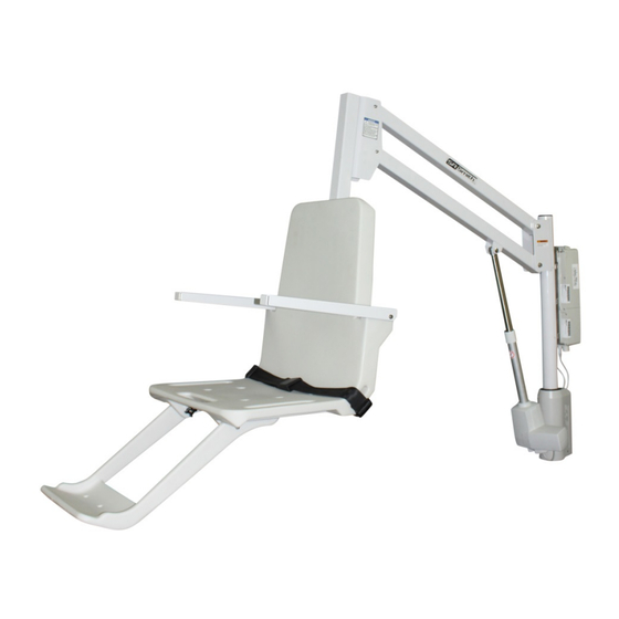
Page 6: Product Overview
The aXs2 is powered by a 24 Volt DC rechargeable battery. The lifting motion is provided by a screw driven electronic actuator and an electronic gear motor provides the turning motion. S.R.Smith has endeavored to design the safest possible lift system, however, lift users are responsible to follow all instructions in the owner’s manual, and all product labels to help ensure safe, reliable and proper... - Page 7 COMPONENT DESCRIPTION The lift is made up of several components: Base Assembly - Mounts to the pool deck and contains the turning elements of the lift. Base Insert Stem - Slides into the square anchor sleeve that is installed on the pool deck. Mast - The main vertical component of the lift.
- Page 8 The Emergency Alert (audible and LED) can be activated by pressing any two buttons on the hand control at the same time (provided with the lift). This will stop all lift movement and activate the audible alert and the Red LED will flash. Once both buttons are released, the lift will return to normal operation and the emergency audible alert will silence.
- Page 9 continues to flash, either the battery voltage is too low (battery pack needs to be replaced), or the battery charger is not properly connected to the battery. Amber Light on Steady – Whenever the amber light is on steady, a battery is connected properly to the charger and the charger is charging the battery.
-
Page 10: Unpacking & Assembly Instructions
- cleanse seat and seatbelt immediately with the above disinfectant solution. Do not use seat or seatbelt if it is damaged or becomes worn out. This lift seat assembly is designed to be used exclusively with S.R. Smith aquatic access lifts. UNPACKING & ASSEMBLY INSTRUCTIONS... - Page 11 It is important that any damage be noted on the Bill of Lading prior to signing for the delivery. Contact either S.R. Smith or your dealer immediately to notify us of any damage or missing parts.
- Page 12 7. Attach the Battery Pack (#4) to the Control Box (#2) by sliding onto the top of the Mounting Plate and down onto the Control Box. To remove battery, pull slightly away from Mounting plate and lift Battery Pack off of the Control Box. (#4) (#2) 8.
- Page 13 12. Attach the opposite end of the Actuator (#1) to the Actuator Arm Assembly (#12) using (1) Bolt (#23), (2) Washers (#16) and (1) Nut (#22) through the holes in the flanges of the Actuator Arm (see image below). 13. Attach the Support Arm Assembly (#13) to the upper holes in the Mast flanges by installing (2) Bushings (#21) into the holes in one end of the Support Arm, then insert the Arm with Bushings between the flanges of the Mast and align to the upper holes in the Mast flanges.
- Page 14 15. Attach the opposite ends of the Actuator Arm Assembly (#12) and Support Arm Assembly (#13) to Seat Bracket with (2) Bolts (#17), (4) Washers (#16) 4) Bushings (#21) and (2) Nuts (#22) in appropriate holes of the Seat Bracket (as shown below), following the same sequence as in previous step.
- Page 15 16. Locate Seat Assembly (#15) and attach to Seat Frame (#14) using (1) Screw (#28), (2) Washers (#29), and (1) Acorn Nut (#30). Tighten using (2) ½” Box Wrenches. (#30) (#29) (#14) (#15) (#28) 17. Attach Footrest (#27) to Seat using (2) Screws and (2) Thumbnuts through holes on bottom of Seat and Footrest.
-
Page 16: Using The Axs2 Lift
User. If the aXs2 will be used by a disabled person living on their own, a communication device should be installed in the area of use to call for assistance in the event of an emergency. Only persons healthy enough for water activities should use the aXs2. - Page 17 The deck anchor reaction loads can be found in the Specification Section of this manual. Once installed, you can lock the aXs2 lift into place by rotating the lift out of the way and removing the back housing of the base, using the provided hardware with a 9/16 socket wrench to tighten it into place.
-
Page 18: Standard Accessories/Optional Accessories
Seat Belt Assembly - Nylon water-resistant belt for added security. • Battery/Charger – 24-volt rechargeable battery. Optional accessories may be purchased for your aXs2 lift through your Authorized Reseller. The following accessories are available: Console/Battery Cover – P/N 910-1000: Protects battery and control unit from exposure to moisture... -
Page 19: Trouble Shooting
Activate the up and down buttons on the hand control. If lift rotates, the problem is likely the hand control. If lift does not rotate, the problem is likely the 24v motor. 7. Contact your Authorized Reseller or S.R. Smith for replacement information. Does lift raise or lower? 1. -
Page 20: Long-Term Storage
2. Write down or take a photo of the serial # sticker from the product. S.R. Smith provides a serial # for every pool lift we produce. The sticker with the serial number can be found at the bottom of the mast near the base. -
Page 21: Specifications
SPECIFICATIONS aXs2 EU/K 1. Dimensions/Capacity Mast Height 45.1”/115 cm Height-Arm Raised 63.2”/160.5 cm Seat Width 23”/58.5cm Overall Length-extended 75.9”/193 cm Storage Length-w/o chair 47”/19 cm Unit Weight- w/ chair 120 lb/54 kg Unit Weight-w/o chair 106 lb/48 kg Power 24 VDC Battery Life 30 cycles (approx.) -
Page 22: Parts List
Screw, Hex Hd - #5/16-18 x 4.0” L 800-0310 Washer, Flat - #5/16” 800-0202 Acorn Nut, #5/16” AX9006 aXs2 Total Cover (Optional Accessory, not shown) 900-6000 Stability Strap (Optional Accessory, not shown) 970-5000 Seat Cover (Optional Accessory, not shown) 910-1000... - Page 23 APPENDIX A 700-3002-BC 10.18.2017...
- Page 24 APPENDIX B 700-3002-BC 10.18.2017...
Need help?
Do you have a question about the aXs2 and is the answer not in the manual?
Questions and answers