
Related Manuals for Sanken SAMCO-NS Series


Summary of Contents for Sanken SAMCO-NS Series
- Page 1 Compact Vector Control Inverter VVVF Inverter SAMCO-NS series Instruction Manual ( Simple Version SANKEN ELECTRIC. CO., LTD.
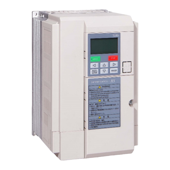
- Page 2 LCD Display Warning Notification Plastic outlook frame Rating nameplate Terminal block Radiator structure Grounding terminal Checking the product and precautions on use Checking the product ■ Product body: NS Vector Control Inverter Body (For example: NS-4A017-B):...
- Page 3 The contents of the model Voltage Class Internal Code Load Mode 3Ø-400V B: 120% 1 Min. Series Name Rated Current A017: 17A Capacity: 7.5KW Rating nameplate...
- Page 4 Connection with peripheral device Draft for the connection with peripheral device Power Supply Input power supply transformer Wiring circuit breaker Leakage circuit breaker Electromagnetic contactor AC reactor Zero-phase reactor Radio noise filter /noise filter DC reactor Zero-phase reactor...
- Page 5 ■ Installation in the side of left / right : Pls. assure the space is above 5cm, whatever is between the inside of cabinet and the outlook frame of Inverter, or between Inverter’s outlook frame while installed in the side of left/right Or could be caused of not enough of heat dissipation for Inverter.
- Page 6 ■ Installation more layers in the side of up /down: Pls. assure the distance is above 20cm, whatever is between the inside of cabinent and the outlook frame of Inverter, or between the Inverter’s outlook frame, and ensure the ventilation and cooling for each Inverter, or will be caused of being not enough of heat dissipation.
- Page 7 ■ Installment site for ventilation fan in the cabinent: ■ Notification: ◆ When several inverters are set in a control cabinet, be sure to local the ventiliation fans properly to allow free aire circulation. ◆ Ensure the air in the outside of cabinent flow to the Inverter’s heat dissipation route, take those heat from the Inverter in operation away in efficient.
- Page 8 Removal and Installation of the front cover (1)Removal of front cover (Lower) Unscrew the M4 screws, dismantle as the below Pic. Pls. carry out this work during the main circuit wiring、control circuit wiring. ◆...
- Page 9 (2)Changed fan Carry out this work only under changing fan. (3)Installation On installation, carrry out this work as the reverse procedures.
- Page 10 Terminal Connection Draft DC reactor (optional selection) Brake Unit Terminal in Main circuit (Optional) Input terminal Braking Resistor (Optional Selection) Output terminal Communication terminal Isolation cable Input Power 3 phase inductive motor 3Ø 380~460V Main Circuit 50/60Hz MCCB Relay contact output Digital Power 24V Contact capacity:250V,0.3A Load Current<150mA...
- Page 11 Composition of Main Circuit Terminals Description of Main Circuit Terminals Terminal Symbol Name Description R,S,T Input Power Terminals Terminals connected to 3 phase commercial power supply U,V,W Terminals connected to 3 phase induction motor Inverter output terminals P,P1 Terminals connected to DC reactor *1 DC reactor connection Terminals Brak Resistor connection...
- Page 12 Distribution Terminal For Main Circuit 1.NS-4A003-B、NS-4A004-B、NS-4A006-B -11-...
- Page 13 2.NS-4A009-B、NS-4A013-B、NS-4A017-B -12-...
- Page 14 3.NS-4A024-B、NS-4A032-B、NS-4A038-B -13-...
- Page 15 Main circuit terminal connection draft Shorten Plate Reactor Motor Optional Accessory Power Supply Braking Resistor Capacities of MCCB and MC and wire size ◎ MC(Electromagnetic contactor) MCCB Model No. (Leakage circuit brakerer) Rated Current Rated making current NS-4A003-B NS-4A004-B NS-4A006-B NS-4A009-B NS-4A013-B NS-4A017-B...
- Page 16 Recommend Wire Size Main Circuit Max. [mm ] Tightening Recommended wire size Screw Torque Wire size P、P1 diameter Input Wire R、S、T U、V、W Grounding wire N·m PR、X NS-4A003-B 2.0 (2.0) 2.0 (2.0) 2.0 (2.0) 2.0 (2.0) 2.0 (2.0) 2.0 (2.0) NS-4A004-B 2.0 (2.0) 2.0 (2.0) 2.0 (2.0)
- Page 17 External brake resistor(Recommend) External brake resistor (limit value) Model No. Resistor value Capacity Resistor value Capacity ※ ※ NS-4A003-B 700Ω or above 100W 420Ω or above 300W NS-4A004-B 700Ω or above 100W 420Ω or above 300W NS-4A006-B 320Ω or above 200W 190Ω...
- Page 18 Composition of Control Circuit Terminals Wire size Terminal screw diameter:M3 Recommend wire size:0.75[mm Tightening torque:0.5[N•m] The arrangement of control circuit terminals is as shown in the following ■ Most Attention: ▲ Don’t input stronger voltage to the control terminal! Or control board burnt ▲...
- Page 19 Function of control circuit terminals Type Terminal Terminal Name Function Description Rated Specification Symbol Digital signal common Common terminals for digital input and Total current consumed: terminals output signals and 24V power supply 100mA or less Input resistor:about 6.6kΩ Multi-Functional input Signals valid while the short terminals -circuited between DIX and...
- Page 20 LCD Operation Panel Status Display Inverter status during operation /stop <Frequency> <Output Current> <Roatation Speed> <load factor> <Output Voltage> <Pressure Value> Name and Function for each part of panel Inverter Condition Information Seconda ry scree n Primary screen Units Direction Key Description:...
- Page 21 Function Code Display Code No. and data For example: Push 【PR/CL】 Key, secondary screen shown F1001, and Primary screen show the value of F1001 Push【ENTER】Key, Primary screen flashing, and revise data through【 ∧ ∨ 】 、 【 】 、 【<】 、 【>】 Push【ENTER】Key, parameters setting successfully Operation panel display mode: Prmary screen and Secondary screen classified by【Status Display】and【Function Code Display】...
- Page 22 Operation mode display Action status Display content Stop Operation lamp “off”, Stop lamp “on” Operation Operation lamp “on”, Stop lamp “off” Operation lamp “flashing”, Stop lamp “flashing” Fault Monitor mode display content Display content Unit 7-Segments LCD display On operation:That is output frequency Frequency At stop: That is setting frequency Output current...
- Page 23 During status monitor display, frequency setting as the below method whatever is on operation or at stop For Example:From 5Hz to 45Hz Operation Display Description Status monitor display(Frequency display) Input value display the last right digit. (Revise the value while this digit flashing) ( 1) ※...
- Page 24 Press【∧】key, changing number to 14, second display parameters number 14 flashing, may be revised again. ∧ 【 】*4 Press【>】key switch to parameters number revised mode, second display parameters number 01 flashing, the value could be revised 【>】 Press【∧】Key, parameters number revise to 14, Seondary monitor parameters number 14 flashing, ∧...
- Page 25 Primary monitor parameter value 1 flashing, that is meaning to be revised the current value. 【ENTER】 Press 【 】key, to change the revised value ∧ to 10 ∧ 【 】 Press 【ENTER】key, primary monitor show the setting value, secondary monitor show flashing, remind to the final 【ENTER】...
- Page 26 For example: Display the disfference with the factory preset Operation Display Description Select function code F1602 (Changed code display function) Press【ENTER】Key, entered into the parameters setting condition. 【ENTER】 Press【∧】/【∨】or digit keyboard, select 1. ∧ ∨ 【 】/【 】 F1602=1 , this will compare the factory presets with Or digit keyboard current function code data.
- Page 27 Alarm status confirmation Alarm status confirmation is the function shown the Inverter status in case of a Alarm. It could be confirmed for alarm status during the latest 5 times through function code F1806~F1810 New alarm happened, the easliest alarm will be deleted. That is latest alarm in F1806, and the earliest one in F1810.
- Page 28 1:Display name as below: ※ Display Content Unit Alarm Name Output Frequency Output current Output Voltage Dc Voltage Output Power Radiator Temperature ℃ ※2 The value displayed is the status before the occurrence of an alarm. Therefore, if an alarm is caused by transient over-current, over voltage he stored value is the different from the current value、voltage value on the alarm.
-
Page 29: Function Code
Function Code Representation and Description of Function Code By changing the function code, Inverter action can be changed Function code are functionally classified into “function blocks” Function Function Block Function Block Name F10xx Basic function F11xx Basic operation function Starting• Braking function F10xx~F13xx F12xx Display function... - Page 30 Function Code List Basic Operation Function F10xx~F13xx Runing Function F10xx~F13xx Setting Factory Code Function Name Data Content resolution preset 1:V∕f Control Mode 1001 Motor control mode 2:Speed Control(Speed sensorless vector control) selection 3:Speed Control(Speedy sensor vector control) 10:Auto tuning mode 1 11:Auto tuning mode 2 40:V•f separation control 1:Operation Panel...
- Page 31 Setting Factory Code Function Name Data Content resolution preset 1007 Upper frequency limit 5~600Hz 0.01Hz 1008 Lower frequency limit 0.05~200Hz 0.01Hz 0.05 5~130 1009 Carrier frequency ※ 1:Random Soft Carrier Mode 1 adjustment 2:Random Soft Carrier Mode 2 3:Random Soft Carrier Mode 3 4:Random Soft Carrier Mode 4 1:Linear 1010...
- Page 32 Setting Factory Code Function Name Data Content resolution preset 1028 2 Start of S-shaped 0~200% Acceleration 1029 2 End of S-shaped 0~200% Acceleration 1030 Gradient of middle of 2 0~100% S-shaped acc. 1031 2 Start of S-shaped 0~200% Deceleration 1032 2 End of S-shaped 0~200% Deceleration...
- Page 33 Setting Factory Code Function Name Data Content resolution preset 1103 Starting frequency 0.05~60Hz 0.01Hz 1104 Operation start frequency 0~20Hz 0.01Hz 1105 Start delay time 0~5 sec. 0.1sec. 1106 Start standby time 0~120 sec. 0.1sec. 1107 Start standby frequency 0.05~60Hz 0.01Hz 0: Do not start 1108 Restart after momentary...
- Page 34 Setting Factory Code Function Name Data Content resolution preset 1118 DC braking start 0.05~60Hz 0.01Hz Frequency on stop 1119 DC braking time 0.1~6500.0 sec. 0.1sec. 1120 DC braking time 0.1~6500.0 sec. 0.1sec. 1121 DC braking time 0.1~6500.0 sec. 0.1sec. 1122 DC braking force F1 1~10 1123...
- Page 35 Setting Factory Code Function Name Data Content resolution preset 1:No units(Multiple of F1203 ) 1202 State display selection 2:Output voltage [V] 3:Dc voltage [V] 4:Active power [kW] 5:Apparent power [kVA]. 6:Radiator Temperature [℃] 7:Command Speed [rpm] 8:PID1 feedback value [Hz] 9:PID2 feedback value [Hz] 10:VRF analog input value [Hz] 11:V/I analog input value [Hz]...
- Page 36 Setting Factory Code Function Name Data Content resolution preset Operation direction 0: Start from the direction opposite to current 1309 Switching in v/f control directiorn after a stop mode 1: Continuous Operation 1315 Shotest operation time 0~99.99 sec. 0.01 sec. function 1316 2 upper frequency...
- Page 37 Function Code List-Input/Output Functions F14xx~F16xx Input/Output Functions F14xx~F16xx Setting Factory Code Function Name Data Content resolution preset 1401 Bias frequency 0~±600 [Hz] 0.1 [Hz] (Frequency at 0V ) (VRF) 1402 Gain frequency 0~±600 [Hz] 0.1 [Hz] (frequency at 5V / 10V ) (VRF)...
- Page 38 Setting Factory Code Function Name Data Content resolution preset 1414 Input terminal DI1 0:Unused 1:FR, 1415 Definition 2:RR, 3:2DF, 1416 Input terminal DI2 4:3DF 5:MBS, 6:ES, 7:RST, 1417 Definition 8:AD2, 9:AD3 1418 Input terminal DI3 10:JOG, 11:5DF, Definition 12:9DF, 13:FR+JOG, Input terminal DI4 14:RR+JOG,...
- Page 39 Setting Factory Code Function Name Data Content resolution preset 1422 Reference frequency 1000~60000 1000 for pulse input 1423 7~10bit 1bit Effective number of bits for VRF detection 1424 7~10bit 1bit Effective number of bits for 位数 V/I detection 1501 Internal analog output 0: No Function function 1 1: Set frequency [Hz]...
- Page 40 Setting Factory Code Function Name Data Content resolution preset 1504 Internal analog output 0:No function Function 2 1:Set frequency [Hz] 2:Output frequency [Hz] 3:PID1 feedback value [Hz] 4:PID2 feedback value [Hz] 5:Output current [A] 6:Output voltage [V] 7:DC voltage [V] 8:Radiator temperature [℃] 9: Load factor [%] (accumulated vale of electric thermistor)
- Page 41 Setting Factory Code Function Name Data Content resolution preset 0: Unused 1509 Selection of output 1: In operation 1 terminal DO1 2: Undervoltage 3: End of simple scheduled operation 4: In operation 2 5: Frequency matching (1 speed frquency) 6: Frequency matching (1 speed frequency) ~16 7: Frequency approach...
- Page 42 Setting Factory Code Function Name Data Content resolution preset 0: Alarm contact 1513 Relay contact output 1: In operation 1 Selection 2: Undervoltage 3: End of simply scheduled operation 4: In operation 2 5: Frequency matching (1 speed frequency) 6: Frequency matching(1 speed frequency)...
- Page 43 Function Code List – System-Related Functions F16xx~F18xx System-related Functions F16xx~F18xx Setting Factory Code Function Name Data content resolution preset 0:No function 1601 Copy Function 1: Transfer current code data to the operation panel (Optional accessories) 2: Transfer the contents stored by operation panel to the inverter (Excluding motor parameters measured)...
- Page 44 Setting Factory Code Function name Data content resolution preset 0: No function 1703 Output current limit 1: Yes, V/f mode(Current acceleration/deceleration at constant speed time) 2: Yes, V/f mode( 1 acceleration/deceleration time) 3: Yes, V/f mode(2 acceleration/deceleration time) 4: Yes, V/f mode (3 acceleration/deceleration time)...
- Page 45 Setting Factory Code Function Name Data content resolution preset 1710 0:Disabled Carrier frequency varied by lowering temperature 1:Enabled (Active when only A mode selected) 1801 Inverter host software Read only Version Version query 1802 Memory version query Read only Version 1803 Operation panel software Read only...
- Page 46 Special Functions F19xx~F20xx Special Functions F19xx~F20xx Setting Factory Code Function Name Data Content resolution preset 0:No function 1901 Energy-saving mode 1:Simple energy-saving mode(V/f mode) selection 2:Auto energy-saving mode 1902 0~50% Simple energy-saving rate 1903 0~65000 sec, 1sec. Simple energy-saving time 1:V·f proportional separation 2001 V·f separation function...
- Page 47 Graph operation function F21xx~Fxx Graph operation function F21xx~Fxx Setting Factory Code Function Name Data Content resolution preset 2101 frequency 0~600Hz 0.01Hz 2102 frequency 0~600Hz 0.01Hz 2103 frequency 0~600Hz 0.01Hz 2104 frequency 0~600Hz 0.01Hz 2105 frequency 0~600Hz 0.01Hz 2106 frequency 0~600Hz 0.01Hz 2107 frequency...
- Page 48 Factory Setting Code Function Name Data Content preset resolution 2214 Operation timerT12 0~65000 sec. 1sec. 2215 Operation timerT13 0~65000 sec. 1sec. 2216 Operation timerT14 0~65000 sec. 1sec. 2217 Operation timerT15 0~65000 sec. 1sec. 2218 Operation stop timer 0~65000 sec. 1sec. Midway stop 1:1 deceleration time(value of F1016 )...
- Page 49 Setting Factory Code Function Name Data Content resolution preset Forward/reverse and 2231 Acceleration/deceleration in T11 Forward/reverse and 2232 Acceleration/deceleration in T12 Forward/reverse and 2233 Acceleration/deceleration in T13 Forward/reverse and 2234 Acceleration/deceleration in T14 Forward/reverse and 2235 Acceleration/deceleration in T15 0: No analog input 2236 Disturb modulation 1: External analog VRF voltage(0~5V)...
- Page 50 Display Function F23xx Display Function F23xx Setting Factory Code Function Name Data Content resolution preset LCD contrast adjustment 2301 1~16 0:No display 2303 LCD ‘s 1 screen 1:Frequency[Hz] display parameters 2:Output current[A] setting(1-5) 3:Speed[rpm] 4:Load factor[%] 5:Output voltage[V] 6:DC voltage[V] 7:Active power[kW] 8:Apparent power[kVA] 9:Radiator Temperature[℃]...
- Page 51 Setting Factory Code Function Name Data Content resolution preset 1:No unit(Multiple of F1203 ) 2304 LCD ‘s 2 screen 2:Output voltage [V] display parameters 3:DC voltage[V] setting 4:Active power [kW] 5:Apparent power [kVA]. 6:Radiator temperature [℃] 7:Command speed [rpm] 8:PID1 feedback value [Hz] 9:PID2 feedback value [Hz] 10:VRF analog input value [Hz] 11:V/I analog input value [Hz]...
- Page 52 PID Function F30xx~F33xx PID Function F30xx~F33xx Setting Factory Code Function Name Data Content resolution preset 1:Frequency 3001 PID1 command value input 2:External analog VRF voltage(0~5V) switching 3:External analog VRF voltage(0~10V or potentiometer) 4:External analog V/I voltage(0~5V) 5:External analog V/I voltage(0~10V or potentiometer) 9:External analog V/I current(4~20mA)...
- Page 53 Setting Factory Code Function Name Data Content resolution preset PID1 operation polarity 1:Command value-feedbakck value 3011 switching 2:Feedback value-command value 1: The positive or negative deviation indicates the 3012 PID1 gain polarity switching same gain 2: The positiveor negative deviation indicates the different gain 3013 PID1 command value...
- Page 54 Setting Factory Code Function Name Data Content resolution preset 0:No input 3102 PID2 Feedback input 1:External analog VRF voltage(0~5V) switching 2:External analog VRF voltage (0~10V or potentiometer) 3:External analog V/I voltage(0~5V) 4:External analog V/I voltage (0~10V or potentiometer) 8:External analog V/I current(4~20mA) 10:Communication mode -53-...
- Page 55 Setting Factory Code Function Name Data Content resolution preset 3103 PID2 control proportional 0~100 0.01 gain 3104 PID2 control integral 0.01~100 sec. 0.01 sec. Time 3105 0~100 sec. 0.01 sec. PID2 control dividential Time PID2 control integral 3106 5~100% 0.1% (Upper frequency limit reference)...
- Page 56 Setting Factory Code Function Name Data Content resolution preset Frequency corresponding 3119 0~600Hz 0.01Hz to PID2 control max. command value 3123 1:Direct input mode PID start mode seleciton 2:Condition input mode 1:Direct end mode 3124 PID end mode selection 2:Condition end mode 3125 PID end setting value 1~100%(upper frequency limit standard)...
- Page 57 Setting Factory Code Function Name Data Content resolution preset 3303 Read only Reading PID1 input Deviation 3304 Reading PID1 output Read only Value 3305 Read only Reading PID2 command Value 3306 Reading PID2 feedback Read only Value 3307 Reading PID2 input Read only Deviation 3308...
- Page 58 Water Supply Function F34xx Water Supply Function F34xx Setting Factory Code Function Name Data Content resolution preset Water supply mode 3401 0:Water supply function disabled Selection 1:Single Pump Mode Lower limit range 3402 0.1~10 Min. 0.1min. continued time T1 Sleep wake up ratio 3403 30~95%...
- Page 59 Communication Functions F40xx~F41xx Communication Functions F40xx~F41xx Setting Factory Code Function Name Data Content resolution preset 4001 Message checksum 0:No 1:Yes 4003 0:No Pull up/Down function 1:Yes Communication response 4004 10~6000ms time 0: No function 4005 Serial communication 1: Dedicated protocol communication function function 2:...
- Page 60 Motor Parameters F5xxx Motor Parameters F5xxx Setting Factory Code Function Name Data Content resolution preset 5001 Motor poles voltage X Y ZZZ — ※ capacity X:Poles Y:Rated Voltage Z:Motor Capacity 5002 Motor current rating 0.1~999.9A 0.1A ※ About 30~110% of the Inverter current rating 5003 Motor frequency rating 10~600Hz...
- Page 61 75kW or above 0.01 0.01mH ~ 600mH 5012 Motor rotator inductance 55kW or below 0.1mH ~ 6000mH 75kW or above 0.01 0.01mH ~ 600mH 5013 Motor’s mutual inductance 55kW or below 0.1mH ~ 6000mH 75kW or above 0.01 0.01mH ~ 600mH 5014 0.01~650A...
- Page 62 Vector Control F60xx Vector Control F60xx Setting Factory Code Function Name Data Content resolution preset 6001 Torque limiter A Mode 0~200% 0.1% (Power running) B Mode 0~150% 0.1% 0:F6001 6002 Torque limiter analog 1:External analog VRF voltage(0~5V) Input function 2:External analog VRF voltage(0~10V or potentiometer)...
- Page 63 Setting Factory Code Function Name Data Content resolution preset 6014 0:No Function Motor virbration reduction rate 1:75% 2:50% 3:25% Lower frequency limit 6015 0~240Hz 0.01Hz for motor vibration reduction function Upper frequency limit 6016 0~240Hz 0.01Hz For motor vibration reduction 6017 0~100% 0.1%...
- Page 64 ■ Water supply function code description F3401 F3401 Water Supply Mode ■ F3401=0,Water supply function disabled ■ F3401=1,Selected single pump water supply Please set the related code with pressure as the actual needing:F3405(pressure command) 、 F3406(analog feedback: pressure bias) 、F3407(analog feedback:pressure gain) F3402 Lower limit range continued time Tl...
- Page 65 F3406 is valid code under the control mode of pressure command given While F3002=1、3、5 : Set pressure value at 5V While F3002=2、4、6 : Set pressure value at 10V While F3002=7、8、9 : Set pressure value at 20mA F3407 Analog feedback lower pressure limit F3407 is valid code under pressure command given control mode.
- Page 66 Energy-saving Function Energy-saving Function F1901 Energy-saving mode selection F1902 Simple energy saving rate F1903 Simple energy saving time These codes are for the selection of energy saving mode、parameters setting for the operation of energy saving. Code Function Name Data Content Setting resolution Factory preset 0: No Function...
- Page 67 ■ F1903=0~65000 This code is used for setting the delay time of running energy-saving while the conditions are ready. While Inverter finished acclerating and running stable, is satisified to simple energy saving, set the value of F1903 in order to find the suitable time into the operation of simple energy-saving mode. Operation command Output frequency Simple energy-saving time...
- Page 68 For example:Inverter max. output voltage is 440V run at 22.7Hz output voltage 200V, and simple energy-saving rate is 50%, it is needing 0.23 sec. from 100V up to 200V when exited from the simple energy-saving action, and then do the action of deceleration while the voltage was recovered. ■...
- Page 69 ◆Auto saving control is effective during constant torque operation. When rated speed has been exceeded during constant power operation, a weak magnectic control will be adpted as normal modes. ■ Compliment description for energy-saving functions ◆On the occasion of energy-saving、Motor speed control、the others feedback control using at the same time, enginer-saving function could be executed with PID control functio if the system was installed sensor.
- Page 70 Alarm list 7-segment Alarm Check points Actions monitor description display Memory Turn off the power, while CHARGE Contact the supplier Abnormality Lamp turn off, turn the power on again, And check the alarm. System Excessive external noise? Install a noise collector or filter Are the signal and power lines Keep the signal line far away from the Abnormality...
- Page 71 Turn off the power, while CHARGE AL10 System Contact the local supplier lamp turns of, turn the power on Abnormality again and check the alarm again. Overload Setting for output current limiting ACER Increase the setting value of F1701 prevention during function is too small? acceleration Pronlong acceleration/deceleration time...
- Page 72 7- segment Alarm Actions Check points monitor descripation display Momentary overload Excessive deceleration rate with Extend the deceleration time. oCPd during deceleration Decrease the setting value. setting for current limiting function (F1701) too high? Overload during Motor operated with an excessive Reduce the load.
- Page 73 7- segment Alarm Check points Actions monitor description display Over-shoot or under-shoot GAL 2 Overspeed Confirm speed command value or happened? torque command value. Modbus Communication cable GAL 3 Confirm communication cables are communication disconnected? timeout connected securely. +24V power supply output from PonG Power supply Check the +24V output power supply for load...
- Page 74 Fault Analysis Problem Check points Voltage at input termianls R、S、T are normal? Main circuit Whether is the motor wired correctly? Load too heavy? Load side Motor locked? Starting frequency setting too high (F1103)? Operation start frequency (F1104) setting too high? Operation command selected for control by external signal (F1102=2)? Motor does not rotate Operator panel...
- Page 75 SANKEN L.D. CO., LTD. Address: RM.703 Concordia Plaza, 1 Sciences Museum Rd., T.S.T. H.K. Phone:+852-2721-3611 Fax:+852-2721-6405 Published in Jun. 2016 Sanken L.D. Co., Ltd.
Need help?
Do you have a question about the SAMCO-NS Series and is the answer not in the manual?
Questions and answers