Advertisement
550-510, 550-511, & 550-516
QUICK START MANUAL
SNIPER EFI INSTALLATION INSTRUCTIONS
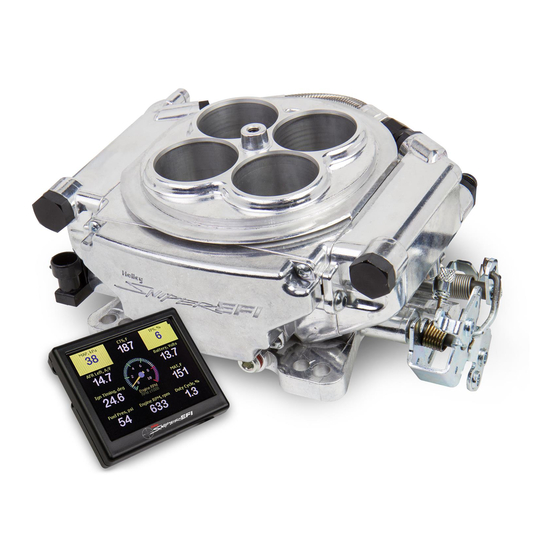
Congratulations on your purchase of a new Sniper EFI Throttle Body System built
by craftsmen to exacting standards in our Bowling Green, Kentucky facility. Every
Sniper EFI System is 100% tested before it leaves our facility for "bolt on and go"
performance.
1
Advertisement
Table of Contents

Related Manuals for Holley Sniper EFI 550-510


Summary of Contents for Holley Sniper EFI 550-510
- Page 1 550-510, 550-511, & 550-516 QUICK START MANUAL SNIPER EFI INSTALLATION INSTRUCTIONS Congratulations on your purchase of a new Sniper EFI Throttle Body System built by craftsmen to exacting standards in our Bowling Green, Kentucky facility. Every Sniper EFI System is 100% tested before it leaves our facility for “bolt on and go” performance.
-
Page 2: Introduction & System Requirements
Any RTV silicone sealants used on the engine are sensor safe Any square flange Holley type intake manifold will work. A spread bore intake manifold may work with no adapter as long as it is an aftermarket “universal flange” (meaning it has dual bolt patterns), and as long as it has enough material such that no vacuum leaks occur along the perimeter of the throttle body. - Page 3 Sniper EFI Wiring Harness Overview Before you get started – Are you experiencing any underlying problem? Holley Performance highly recommends the following items be checked and/or corrected prior to installation of your new Sniper EFI system to ensure optimum performance from your engine.
- Page 4 Throttle Linkage/Bracket Side View Reconnect the throttle and transmission kick-down linkage. Be sure to check for any binding conditions and correct before proceeding. Install the Coolant Temperature Sensor into a 3/8” NPT coolant passage in either the intake manifold or cylinder head. Do not overtighten or damage to the cylinder head or intake may occur.
- Page 5 Locate a position for the oxygen sensor as close to the engine as possible. The oxygen sensor should be mounted at a point where it can read a good average of all the cylinders on one bank. This would be slightly after all the cylinders merge. If you have long tube headers, mount the sensor approximately 1-10”...
- Page 6 Ignition Option 2 10. Option 2. Capactive Discharge Ignition – “C/D Box” - Locate the small 1 wire ignition adapter. It has a single PURPLE wire attached to a 2 pin connector (shown below). Connect this wire to the distributor connector on the main harness. The PURPLE wires should plug into each other –...
-
Page 7: Additional Inputs And Outputs
Used to drive an aftermarket tachometer Digital Gauge Output Used to drive Holley EFI analog gauges via 554-130 Gauge Module NITIAL POWER-UP AND WIZARD Turn the ignition key to the “run” position. This should apply power to the ECU as well as the Sniper EFI Handheld control module. - Page 8 It is now time to begin the Calibration Wizard! NOTE: DO NOT ATTEMPT TO START THE VEHICLE UNTIL YOU ARE TOLD TO DO SO IN THE INSTRUCTIONS BELOW. NOTE: The handheld has a SD memory card installed in the side. This card contains specific information that is required for the use of the Sniper EFI product.
- Page 9 Magnetic [timing control optional] Proceed to Step 9 Holley Dual Sync [timing control optional] Proceed to Step 9 C hoose whether your Sniper will control engine timing. For more details on this feature, refer to the Ignition Wiring Section of the Reference Manual ...
-
Page 10: Sensor Verification
If you do not get an RPM signal, there is an error in the wiring or system setup. Call Holley Tech service for advice. If the engine starts but is idling too low and appears to be struggling for air, you may have to open the throttle body idle speed screw at this time. - Page 11 IDLE SETTING/THROTTLE PLATE SETTING Once the engine is up to operating temperature, the idle speed can be set to what was configured in the Wizard. To do this, open up the Initial Startup gauge screen. With the vehicle in neutral, adjust the idle screw until the IAC Position reads between 2 and 10%.
-
Page 12: System Installation Overview
SYSTEM INSTALLATION OVERVIEW...
Need help?
Do you have a question about the Sniper EFI 550-510 and is the answer not in the manual?
Questions and answers