
Subscribe to Our Youtube Channel
Related Manuals for Festo CTEU-CO


Summary of Contents for Festo CTEU-CO
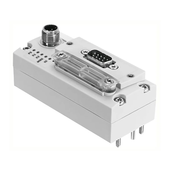
- Page 1 Universal bus node CTEU-CO Manual Functions and maintenance Bus node Type CTEU-CO Fieldbus Protocol CANopen Manual 573 768 en 1101NH [756 466]...
- Page 3 ....... . . 573 768 © (Festo AG & Co. KG, D-73726 Esslingen, 2011) Internet: http://www.festo.com E-Mail: service_international@festo.com...
- Page 4 Installation ® ® ® ® ® CANopen , CiA , TORX , TÜV and VDE are registered trademarks of the respective trademark owners in certain countries. Festo P.BE-CTEU-CO-OP+MAINT-EN en 1101NH...
-
Page 5: Table Of Contents
..........1-21 Festo P.BE-CTEU-CO-OP+MAINT-EN en 1101NH... - Page 6 ............Festo P.BE-CTEU-CO-OP+MAINT-EN en 1101NH...
-
Page 7: Intended Use
Installation Intended use The bus node type CTEU-CO described in this manual has been designed exclusively for use as a slave on the CANopen field bus. The bus node may only be used as follows: – as intended – in original condition, without any modifications by the user. -
Page 8: Range Of Application And Certifications
(PLCs) and slaves on the CANopen fieldbus. Service Please consult your local Festo Service if you have any tech- nical problems. Festo P.BE-CTEU-CO-OP+MAINT-EN en 1101NH... -
Page 9: Notes On This Manual
Information about other bus nodes and components of the CTEU… product family can be found in the user documenta- tion for the respective product. Festo P.BE-CTEU-CO-OP+MAINT-EN en 1101NH... -
Page 10: Important User Instructions
This means that failure to observe this instruction may result in damage to property. The following pictogram marks passages in the text which describe activities with electrostatically sensitive compon- ents. Electrostatically sensitive components may be damaged if they are not handled correctly. VIII Festo P.BE-CTEU-CO-OP+MAINT-EN en 1101NH... - Page 11 Accessories: Information on necessary or sensible accessories for the Festo product. Environment: Information on environment-friendly use of Festo products. Text markings The bullet indicates activities which may be carried out in • any order. 1. Figures denote activities which must be carried out in the numerical order specified.
- Page 12 Cyclic monitoring of the fieldbus station by the master controller by requesting a response within a specified time period. Node ID Address of the fieldbus station Output byte Object Directory makes all important slave parameters accessible in a standardised manner O, I Digital output, digital input Festo P.BE-CTEU-CO-OP+MAINT-EN en 1101NH...
- Page 13 They enable write and read access to any entry in the object directory of a bus node. Status bits Internal inputs which supply coded common diagnostic messages. TPDO Transmit-PDO Voltage supply Umbrella term for operating and load voltage supplies Tab. 0/1: Terms and abbreviations Festo P.BE-CTEU-CO-OP+MAINT-EN en 1101NH...
- Page 14 Installation Festo P.BE-CTEU-CO-OP+MAINT-EN en 1101NH...
-
Page 15: Commissioning
Commissioning Chapter 1 Commissioning Festo P.BE-CTEU-CO-OP+MAINT-EN en 1101NH... -
Page 16: General Information About The Canopen Fieldbus Protocol
..........1-21 Festo P.BE-CTEU-CO-OP+MAINT-EN en 1101NH... -
Page 17: Commissioning
The CTEU… product family enables the creation of a decent- ralised automation system in a CANopen fieldbus network. 1.1.1 Components Higher-order controller (CAN master): e.g. CECX Fieldbus level: CTEU bus node Device level: e.g. valve terminal VTUB-12 Drive level: e.g. linear module HME Festo P.BE-CTEU-CO-OP+MAINT-EN en 1101NH... -
Page 18: Data Exchange With The Canopen Fieldbus Protocol
DS207 DS301, V4.0.2 The Draft Standard 301 is based on the CAL communication profile DS401, V3.0 The Draft Standard 401 defines the device profiles for input and output modules within CANopen Tab. 1/1: Supported CANopen specifications Festo P.BE-CTEU-CO-OP+MAINT-EN en 1101NH... -
Page 19: Brief Overview Of The Scope Of Functions
Receive PDO 1 and 2 – Emergency telegram for fault message to the master controller – Node guarding and Heartbeat – Default setting of all identifiers as per DS301 and the station number (predefined connection set) – Variable mapping Festo P.BE-CTEU-CO-OP+MAINT-EN en 1101NH... -
Page 20: Commissioning Of A Master Controller
(also designated “CAN-Master”). The current EDS file can be found on the Festo website at www.festo.com Support/Downloads. Install this file by using the configuration software of your master controller. -
Page 21: Configuration By Using Process Data
Fig. 1/1: Overview of PDO 1 and 2 for inputs and outputs Note When filling the process data telegrams please note that CANopen specification DS401 is only observed if you fill PDO 1 exclusively with input and output bytes. Festo P.BE-CTEU-CO-OP+MAINT-EN en 1101NH... -
Page 22: Rules For Internal I/O Mapping
1.3.3 I/O linking by COB-IDs COB-IDs are made up of the function code (see Tab. 1/3) and the address of the respective fieldbus station (Node ID): Function Code Node ID Tab. 1/2: Configuration of COB-IDs Festo P.BE-CTEU-CO-OP+MAINT-EN en 1101NH... - Page 23 Node guarding / Cyclic interrogation (guarding) Heartbeat or life sign message: 1793 … 1919 “0” is used as the Node ID. Tab. 1/3: Function Code Examples for using the COB-IDs can be found in section 1.5.3. Festo P.BE-CTEU-CO-OP+MAINT-EN en 1101NH...
-
Page 24: Device Parameters
3301 for a device connected to I-Port 1 or object 3302 for a device connected to I-Port 2. Information about the structure of the device parameters can be found in the appendix, section A, and in the documentation for your device. 1-10 Festo P.BE-CTEU-CO-OP+MAINT-EN en 1101NH... -
Page 25: Communication
“operational” status with a special Network Management Telegram (NMT). Communication via both SDOs and PDOs is possible in this status. With the aid of the NMT telegrams you can switch between the different states, if required. 1-11 Festo P.BE-CTEU-CO-OP+MAINT-EN en 1101NH... - Page 26 1. Commissioning 1.5.2 CANopen status transitions Power On Application initialisation Communication initialisation Pre-operational Stopped Operational Fig. 1/2: CANopen status transitions (for a description refer to Tab. 1/4) 1-12 Festo P.BE-CTEU-CO-OP+MAINT-EN en 1101NH...
- Page 27 The objects 6000 … are always loaded with the default settings after power-on Only after the transition from operational mode to stopped or pre-operational mode Tab. 1/4: Status transitions (for an overview refer to Fig. 1/2) 1-13 Festo P.BE-CTEU-CO-OP+MAINT-EN en 1101NH...
-
Page 28: Examples Of The Communication Sequence
In the example, only output 0 is set, any outputs already set will be reset. (all values in hex) xx xx 01 00 PLC/PC/IPC Fig. 1/4: Example 2, set output 0 of the bus node 1-14 Festo P.BE-CTEU-CO-OP+MAINT-EN en 1101NH... - Page 29 Data bytes 00 10 00 00 00 00 PLC/PC/IPC 00 10 91 01 30 00 (all values in hex) Fig. 1/5: Example 3, index 1000 , read subindex 0 (device type: device profile, device extension) 1-15 Festo P.BE-CTEU-CO-OP+MAINT-EN en 1101NH...
- Page 30 Index and subindex – data bytes (not relevant) 0C 10 04 7F 00 00 PLC/PC/IPC 0C 10 00 00 00 00 (all values in hex) Fig. 1/6: Example 4: Index 100C , Subindex 0 written (Guard Time) 1-16 Festo P.BE-CTEU-CO-OP+MAINT-EN en 1101NH...
- Page 31 (e.g. switched valves) remain set even after a loss of communication, fieldbus interruptions, et c. Node guarding response PLC/PC/IPC (all values in hex) Fig. 1/7: Example 5, start “Node guarding” monitoring ( Remote request) 1-17 Festo P.BE-CTEU-CO-OP+MAINT-EN en 1101NH...
-
Page 32: Switching On
Connect any devices to the bus node via the I-Port, as • these are only recognised by the bus node when the oper- ating voltage is switched on. 1-18 Festo P.BE-CTEU-CO-OP+MAINT-EN en 1101NH... -
Page 33: Switching On The Operating Voltage
If the master controller and the fieldbus stations have separ- ate power supplies, they should be switched on in the follow- ing sequence: 1. Switch on the operating voltage supply for all fieldbus stations. 2. Switch on the operating voltage supply for the controller. 1-19 Festo P.BE-CTEU-CO-OP+MAINT-EN en 1101NH... -
Page 34: Normal Operating Status
Tab. 1/5: Operating status LEDs when switching-on Information about diagnosing using the LED displays can be found in section 2.2. 1-20 Festo P.BE-CTEU-CO-OP+MAINT-EN en 1101NH... -
Page 35: Fail State Behaviour
The “X1” and/or “X2” LED on the bus node illuminate red and remain set “MNS” LED on the bus node illu- (“Hold last minates red state”) Tab. 1/6: Constellations of Fail state behaviour 1-21 Festo P.BE-CTEU-CO-OP+MAINT-EN en 1101NH... - Page 36 Fig. 1/8: DIL switches for Fail state behaviour Further information relating to the DIL switches on the bus node can be found in Part I of the product documentation entitled “Installation and Interface manual”, which is supplied with the bus node. 1-22 Festo P.BE-CTEU-CO-OP+MAINT-EN en 1101NH...
- Page 37 Diagnosis Chapter 2 Diagnosis Festo P.BE-CTEU-CO-OP+MAINT-EN en 1101NH...
- Page 38 ......... . 2-13 Festo P.BE-CTEU-CO-OP+MAINT-EN en 1101NH...
-
Page 39: Diagnosis
Fig. 2/1: DIL switches for diagnostic messages Further information relating to the DIL switches on the bus node can be found in Part I of the product documentation entitled “Installation and Interface manual”, which is supplied with the bus node. Festo P.BE-CTEU-CO-OP+MAINT-EN en 1101NH... -
Page 40: Diagnostics Via Led Display
Diagnostics via LED display LEDs are located on the bus node for diagnosing the bus node and any connected devices (see Fig. 2/2). The LEDs can assume the following states (sometimes in different colours): illuminates flashes Festo P.BE-CTEU-CO-OP+MAINT-EN en 1101NH... -
Page 41: Ps-Led Status Display
Eliminate undervoltage on the con- LED flashes node's I-Port nected device green Signal voltage is not Check signal voltage supply present. (pin 1 and 3) LED is off Tab. 2/2: Status displays of the device-specific “PS” LED Festo P.BE-CTEU-CO-OP+MAINT-EN en 1101NH... -
Page 42: Status Display X1-/X2-Leds
Separate accessory with two interfaces for connecting another device is required. Tab. 2/3: Status displays of the device-specific “X1” LED if device 1 is connected and “X2” if device 2 is connected. Festo P.BE-CTEU-CO-OP+MAINT-EN en 1101NH... -
Page 43: Status Display Mns-Led
LED flashes • Normal operating status/no Diagnosis is possible • communication error on the Access to connected devices is LED is off fieldbus possible through PDO/SDO access Tab. 2/4: Status displays of the fieldbus-specific “MNS” LED Festo P.BE-CTEU-CO-OP+MAINT-EN en 1101NH... -
Page 44: I/O-Led Status Display
• – No commissioning of the No device connected • fieldbus Station number (Node ID) = 0 LED is off – No fieldbus connected is set Tab. 2/5: Status displays of the fieldbus-specific “I/O” LED Festo P.BE-CTEU-CO-OP+MAINT-EN en 1101NH... -
Page 45: Diagnostics Via Fieldbus
Dia- Dia- Dia- gnostics gnostics gnostics gnostics byte 1 byte 2 byte 1 byte 2 Obj. 1001 Obj. 1002 Manufacturer status register CANopen standard Manufacturer specific error field Tab. 2/6: Composition of the Emergency Message Object Festo P.BE-CTEU-CO-OP+MAINT-EN en 1101NH... - Page 46 Short circuit at outputs Operating voltage too low Load voltage too low Hardware fault Node guarding or Heartbeat error Configuration error Diagnostic message from I-Port telegram Tab. 2/7: Bus node Error Codes (as per DS401) 2-10 Festo P.BE-CTEU-CO-OP+MAINT-EN en 1101NH...
- Page 47 3 and 4 or 5 and 6 of the Emergency Message (Manufacturer Status Register, Object 1002). Transmittable error causes The following error causes are reported to the master control- ler by the bus node (Tab. 2/9): 2-11 Festo P.BE-CTEU-CO-OP+MAINT-EN en 1101NH...
- Page 48 X = Error is present on the bus node itself or is not clearly assigned to a device that is connected to the bus node via the I-Port interface. Tab. 2/9: Transmittable error causes via Emergency Message 2-12 Festo P.BE-CTEU-CO-OP+MAINT-EN en 1101NH...
-
Page 49: Reaction To Network Communication Faults
(default: switched off ). In the case of actuators it is advisable to monitor the master controller for failure in order to provide an appropriate emer- gency shutdown strategy. 2-13 Festo P.BE-CTEU-CO-OP+MAINT-EN en 1101NH... - Page 50 (Fault reaction option code object 605Eh, PNU 1021) is executed and the drive is stopped. Select the “Guard Time” with reference to the dynamics of the system. Refer to your master controller documentation for details on how to activate Node guarding. 2-14 Festo P.BE-CTEU-CO-OP+MAINT-EN en 1101NH...
- Page 51 Error treatment Chapter 3 Error treatment Festo P.BE-CTEU-CO-OP+MAINT-EN en 1101NH...
- Page 52 ......3.1.6 Read out diagnostic messages via CANopen ....Festo P.BE-CTEU-CO-OP+MAINT-EN en 1101NH...
-
Page 53: Error Treatment
Part I of the product documentation entitled “Installation and Interface manual”, which is supplied with the bus node. Information for mounting the bus node on the CAPC… electric sub-base can be found in the assembly instructions supplied with the electric sub-base. Festo P.BE-CTEU-CO-OP+MAINT-EN en 1101NH... -
Page 54: Check The Power Supply
Interface manual”, which is supplied with the bus node. Normal status LED PS-LED illuminates green and the X1 and/or X2 LED illuminate green. Error status 1 The operating voltage supply for the bus node exhibits under- voltage: – PS-LED flashes green Festo P.BE-CTEU-CO-OP+MAINT-EN en 1101NH... -
Page 55: Restart Communication Between The Bus Node And The Device
Compare the desired Node ID with the Node ID set on the • bus node (DIL switch setting). Information relating to installing the bus node can be found in Part I of the product documentation entitled “Installation and Interface manual”, which is supplied with the bus node. Festo P.BE-CTEU-CO-OP+MAINT-EN en 1101NH... -
Page 56: Check The Canopen Configuration
2. Check whether Fail State is activated on the bus node (DIL switch position). Fail State off: the outputs are set to “0” after fieldbus communication is restored. Festo P.BE-CTEU-CO-OP+MAINT-EN en 1101NH... - Page 57 Tab. 3/10: Extract from the Emergency Message table (see section 2.3.2) Option 2 Proceed as follows: Retrieve the SDO telegrams manually from the bus node • and evaluate them (see object directory in section A.2) Festo P.BE-CTEU-CO-OP+MAINT-EN en 1101NH...
- Page 58 3. Error treatment Festo P.BE-CTEU-CO-OP+MAINT-EN en 1101NH...
- Page 59 Technical appendix Appendix A Technical appendix Festo P.BE-CTEU-CO-OP+MAINT-EN en 1101NH...
- Page 60 ..........Festo P.BE-CTEU-CO-OP+MAINT-EN en 1101NH...
- Page 61 Relative air humidity as per IEC 60770 93 % at 40 °C Protection class as per EN 60529, bus node IP65/67 with appropriate cable from Festo fitted completely, plug connector inserted or accessories provided with protective cap Protection against electric shock...
- Page 62 – Current consumption (at 24 V DC) of the bus Max. 175 mA node with operation of one/two connected devices via electric sub-base CAPC-… Galvanic isolation Bus interface External fuse required Dependent on the connected device (e. g. valve terminal) Festo P.BE-CTEU-CO-OP+MAINT-EN en 1101NH...
- Page 63 125 kbps 250 kbps 500 kbps 1 000 kbps – Fieldbus cable (“trunk cables”) 500 m 250 m 100 m 40 m – Branch line cable (“drop cables”) 3,75 m 2,00 m 0,75 m 0,3 m Festo P.BE-CTEU-CO-OP+MAINT-EN en 1101NH...
- Page 64 Index Sub- Designa- Type Attr. Map. Values Explanation (hex) index tion (hex) 1000 Device type – 00030191 01 91 = device profile (fixed) DS401 3 = Digital inputs and digital outputs 1001 Error re- – gister Festo P.BE-CTEU-CO-OP+MAINT-EN en 1101NH...
- Page 65 = complete node guarding time) 1014 COB-ID – 00 00 00 80 Default emergency object Emergency COB-ID 80 + node ID Message 1015 Inhibit Time – 00 00 Transmit Blocking Time Emergency Emergency Message Message [100µs] Festo P.BE-CTEU-CO-OP+MAINT-EN en 1101NH...
- Page 66 1200 Server SDO – Number of entries parameter COB_ID 600 + Node ID Default COB-ID + Node ID Client Server (rx) COB_ID 580 + Node ID Default COB-ID + Node ID Server Client (tx) Festo P.BE-CTEU-CO-OP+MAINT-EN en 1101NH...
- Page 67 Inhibit Time 0000 Event Timer 1401 Receive – Output PDO 1 PDO Com- Communication munication Parameter Parameter 1 COB-ID 300 + Node ID Default COB-ID of the outputs Transmis- sion Type Inhibit Time 0000 Event Timer Festo P.BE-CTEU-CO-OP+MAINT-EN en 1101NH...
- Page 68 62 00 0D 08 ... Index A32 … A39 62 00 0E 08 ... Index A40 … A47 62 00 0F 08 ... Index A48 … A55 62 00 10 08 ... Index A56 … A63 A-10 Festo P.BE-CTEU-CO-OP+MAINT-EN en 1101NH...
- Page 69 Mapping Parameter 1 COB-ID 280 + Node ID Default COB-ID of the inputs Transmis- Default: acyclic sion type Inhibit Time 00 00 Transmit blocking time inputs Event Timer Time-controlled transmis- sion of the inputs [ms] A-11 Festo P.BE-CTEU-CO-OP+MAINT-EN en 1101NH...
- Page 70 60 00 0D 08 ... Index E32 … E39 60 00 0E 08 ... Index E40 … E47 60 00 0F 08 ... Index E48 … E55 60 00 10 08 ... Index E56 … E63 A-12 Festo P.BE-CTEU-CO-OP+MAINT-EN en 1101NH...
- Page 71 Device ID Function ID Str. Manufacturer name Manufacturer URL Product name Part no. Product text Serial number Hardware revision Software revision Slave Attribute (I-Port) Extended parameters dependent on the connected device (see product description) Diagnosis types A-13 Festo P.BE-CTEU-CO-OP+MAINT-EN en 1101NH...
- Page 72 (see product description) Diagnosis types 3301 Parameter – Number of entries Device 1 Parameter byte 1 … … Parameter byte 8 (Use dependent on the connected device, see product description) A-14 Festo P.BE-CTEU-CO-OP+MAINT-EN en 1101NH...
- Page 73 6200 Digital Out- – Number of outputs puts (avail- Write Output 16 Bytes able in EDS … Output 1 … 16 (Sequence dependent on standard mapping or indi- vidual mapping) A-15 Festo P.BE-CTEU-CO-OP+MAINT-EN en 1101NH...
- Page 74 A. Technical appendix A-16 Festo P.BE-CTEU-CO-OP+MAINT-EN en 1101NH...
- Page 75 Index Appendix B Index Festo P.BE-CTEU-CO-OP+MAINT-EN en 1101NH...
- Page 76 ............Festo P.BE-CTEU-CO-OP+MAINT-EN en 1101NH...
- Page 77 B. Index Index Abbreviations, Product-specific CE certification Certifications COB-ID 1-8, 1-22 Communication 1-11 Check Examples 1-14 Status transitions 1-12 Configuration Check Process data Diagnostics Emergency message Fieldbus LEDs Messages via CANopen DIL switches Diagnostics Switching positions 1-21 Festo P.BE-CTEU-CO-OP+MAINT-EN en 1101NH...
- Page 78 Manufacturer Status Register Example Load objects 1-15 Node guarding 1-17 Set output 1-14 Start CANopen network 1-14 Write objects 1-16 Fail state 1-21 Heartbeat 1-13, 2-10, 2-11, 2-12, A-8 I/O-LED Important user instructions VIII Intended use Festo P.BE-CTEU-CO-OP+MAINT-EN en 1101NH...
- Page 79 Manufacturer Status Register 2-11 Mapping Rules MNS-LED Network communication faults, Parametrising the fault reaction 2-13 Node guard Node guarding 1-13, 2-10, 2-11, 2-12, 2-13 Example 1-17 Notes on the manual Object Directory Pictograms Pre-defined error field 2-10 PS-LED Festo P.BE-CTEU-CO-OP+MAINT-EN en 1101NH...
- Page 80 B. Index Service Status transitions 1-12 Target group Text markings Transmission of error causes via Emergency Message 2-11 X1/X2-LEDs Festo P.BE-CTEU-CO-OP+MAINT-EN en 1101NH...
Need help?
Do you have a question about the CTEU-CO and is the answer not in the manual?
Questions and answers