Table of Contents
Advertisement
9/27/2017
LMU-3640 Hardware & Installation Guide
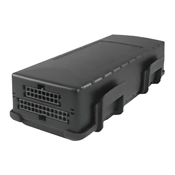
LMU-3640™
Hardware and Installation Guide
IMPORTANT: DO NOT INSTALL OR USE THE SOFTWARE
OR DOCUMENTATION UNTIL YOU HAVE READ AND
AGREED TO THE LICENSE AGREEMENT AND REVIEWED
THE LIMITED WARRANTY AND REGULATORY
INFORMATION.
1 Introduction
Welcome to the LMU-3640™ Hardware and Installation Guide. This
manual is intended to give you information on the basic setup and
installation of the CalAmp LMU-3640™ product(s) including
hardware descriptions, environmental specifications, wireless network
overviews and device installation.
1.1 About This Manual
The LMU-3640™ is one of the most flexible economy mobile
tracking hardware products available. In order to accurately
describe the functionality of these units we have broken this
manual into the following sections:
System Overview - A basic description of a
CalAmp LMU-3640™ based tracking system. This
includes a description of roles and responsibilities
of each of the CalAmp components as well as a
brief overview of the wireless data technologies
used by the LMU-3640™.
Hardware Overview - Describes the physical
characteristics and interfaces of the LMU-3640™.
Installation and Verification - Provides guidance
for the installation of the LMU-3640™ versions in a
vehicle and instructions on how to verify the
installation is performing adequately.
1.2 About The Reader
In order to limit the size and scope of this manual, the following assumptions have been made about the reader.
1. You are familiar with GPS concepts and terminology
https://puls.calamp.com/wiki/LMU-3640_Hardware_%26_Installation_Guide
LMU-3640 Hardware & Installation Guide - PULS Wiki
Contents
1 Introduction
1.1 About This Manual
1.2 About The Reader
3.1 LMU-3640™
3.2 Location Messaging Unit - LMU-3640™
4.2 Activating LTE Using AT Commands
4.3 Auto provisioning of GSM or HSPA LMUs
4.4 Activating GSM or HSPA LMU using AT Commands
4.5 Preparing for Installation
4.6 Plan The Installation
4.7 Installing the LMU in a Vehicle
4.8 Installation Verification
4.6.1 Size and Placement of LMU Unit
4.6.2 Access to the SIM (Subscriber Identity Module) Card
4.6.3 Protection from Heat
4.6.4 Visibility of Diagnostic LEDs
4.6.5 Cable Length
4.6.6 Moisture and Weather Protection
4.6.7 Preventing Accidental or Unauthorized Modification
4.7.1 Place the LMU unit in the vehicle.
4.7.2 Connect power, ignition, and ground.
4.7.3 Typical Connection Sequence
4.8.1 Comm Verification
4.8.2 GPS Verification
4.8.3 Inbound Verification
4.8.4 Verification via SMS
1/23
Advertisement
Table of Contents

Related Manuals for CalAmp LMU-3640

Summary of Contents for CalAmp LMU-3640
-
Page 1: Table Of Contents
4.6 Plan The Installation 4.6.1 Size and Placement of LMU Unit 4.6.2 Access to the SIM (Subscriber Identity Module) Card The LMU-3640™ is one of the most flexible economy mobile tracking hardware products available. In order to accurately 4.6.3 Protection from Heat 4.6.4 Visibility of Diagnostic LEDs... -
Page 2: About Calamp
LMU-3640™ are sold exclusively to authorized systems integrators, software firms, and service providers who have developed their offering around the capabilities of the LMU-3640™. Customers are trained by CalAmp to integrate the mobile device with their system and to assist in support and maintenance of the devices. -
Page 3: Component Descriptions
LMU Manager is the primary support and configuration tool in the CalAmp system. It allows access to almost every feature available to the LMU-3640™. Unlike the backend software, it has the option of talking directly to an LMU-3640™ or making a request forwarded by the LM Direct server. -
Page 4: Lmu-3640
LMU-3640 Hardware & Installation Guide - PULS Wiki 2.2.5 LMU-3640™ The LMU-3640™ is responsible for delivering the location and status information when and where it is needed. Data requests can come from any of the following sources: PEG™ script within the LMU-3640™... -
Page 5: Physical Specifications
9 to 30 VDC. SAE Test: SAE J1455, SAE J1113 Backup Battery The LMU-3640™ supports a Lithium-Ion 1000 mAh backup battery input to be used when primary power is lost; the supported voltage range is 9 to 16 VDC Transient Protection... -
Page 6: Lmu-3640™ Connectors
SAE Test: SAE J1455 Mil Standard 202G and 810F Operating Voltage Range The LMU-3640™ supports vehicles with 12 or 24 VDC systems including transients and electrical system noise; this includes ranges from 7 to 32 VDC. Electrostatic Discharge (ESD) No damage or performance degradation after the ESD disturbance. - Page 7 LMU-3640 Hardware & Installation Guide - PULS Wiki 3.2.1 I/O Connector The LMU-3640™'s features expanded power and I/O capabilities via its 24-Pin Molex 43045-2202 connector. Its pin-out is as follows: *Refer to the Harness Diagrams page for more information on appropriate accessories for the LMU-3640™.
-
Page 8: Vbus Connector
VIN 1 Analog to Digital Input 4 VIN 2 Analog to Digital Input 4 3.2.2 VBUS Connector The LMU-3640™’s features a 16-Pin Molex 43045-1600 connector to the vehicle bus. Its pin-out is as follows: Signal Name Color J1708H Brown J1850-... -
Page 9: I/O Descriptions
3.4.1 3-Axis Accelerometer Input The LMU-3640™ supports an internal 3 Axis Precision Accelerometer as one of its discreet inputs. When the LMU is moved in any direction, the associated input will be in the High state. If the LMU’s accelerometer does not detect motion, then the input will be in the Low state. No external connections are required for this functionality to be operational. -
Page 10: Outputs
Sample Relay Wiring 3.4.4 Status LEDs The LMU-3640™ is equipped with 3 Status LEDs; one for GPS, one for COMM (wireless network status), one for GPS, and one for WiFi. The LEDs use the following colors to indicate service: Status LEDs https://puls.calamp.com/wiki/LMU-3640_Hardware_%26_Installation_Guide... -
Page 11: Configuration And Activation
4 Configuration and Activation This section details how to quickly get an LMU-3640™ provisioned and configured to point at a specific server. It is assumed that a PEG script has already been created and is being managed through LMU Manager or PULS™, the CalAmp Maintenance System.
Need help?
Do you have a question about the LMU-3640 and is the answer not in the manual?
Questions and answers