Table of Contents
Advertisement
Advertisement
Table of Contents

Related Manuals for Keeler All Pupil II


Summary of Contents for Keeler All Pupil II
- Page 1 All Pupil II Indirect Ophthalmoscope Instructions for use Next Next...
-
Page 2: Table Of Contents
Contents Page Page 1. Copyright and trademarks ........... 3 • Slimline lithium ion ............16 2. Introduction ................4 • Charging and charging cycle ........17 3. Symbols .................. 5 • Wall mounting .............. 20 4. Safety ..................6 7. SmartPack and WallPack ............. 22 • Device classification • Parts list • Warnings • Power conversion . -
Page 3: Copyright And Trademarks
1. Copyright and trademarks The information contained within this manual must not be reproduced in whole or in part without the manufacturer’s prior written approval. As part of our policy for continued product development we reserve the right to make changes to specifications and other information contained in this document without prior notice. All Pupil II and All Pupil II LED are registered trademarks of Keeler Ltd 2012. Copyright © Keeler Limited 2012. Published in the UK 2012. Home Back Next... -
Page 4: Introduction
2. Introduction Thank you for purchasing the Keeler All Pupil II Indirect Ophthalmoscope. We have taken the greatest care in the design, development and manufacture of this product to ensure that you get many years of trouble free service. However, it is important that you read the descriptions, installation and operating instructions carefully prior to installing or using your new indirect ophthalmoscope. Please read and follow these instructions carefully. Home Back Next... -
Page 5: Symbols
3. Symbols Read user instructions for warnings, cautions and Follow instructions for use additional information High voltage The CE mark on this product indicates it has been tested to and conforms with the provisions noted Trip hazard within the 93/42/EEC Medical Device Directive Optical radiation hazard Consult instructions for use Hot surface Double insulated Non-ionizing radiation Manufacturer's name and address This way up This Symbol on the product or on its packaging and instructions indicates that it was put on the Keep dry Keep dry market place after August 2005 and that this product shall not be treated as Household Waste Fragile Type B protections against shock Material suitable Material suitable for recycling for recycling Home Back Next Mandatory action sign... -
Page 6: Safety
Carefully read this Instruction Section before using your Keeler area with soap and water. If it contacts the eye, seek medical product. For your own safety and that of your customers attention immediately observe all cautionary information provided in this section. The • US Federal law restricts this device to sale by or order of a following information is intended to highlight potential safety physician or practitioner hazards that can be associated with misuse, or damage. Do not fit mains power adapter into a damaged mains Warnings and cautions outlet socket Route power cords safely to eliminate risk of tripping or Warning damage to equipment • Check your Keeler product for signs of transport / storage damage prior to use Bulbs / LED’s can reach high temperatures in use – allow to cool before handling • Do not use if the product is visibly damaged, and periodically inspect for signs of damage Do not exceed maximum recommended exposure time • Do not use in the presence of flammable gases / liquids, or in After removal of the bulb / LED do not touch the bulb / an oxygen rich environment LED contacts and the patient simultaneously • This product should not be immersed in fluids Home Back Next • Do not disassemble or modify the battery. There are no... -
Page 7: Cautions
4. Safety Caution • Use only genuine Keeler approved parts and accessories or • Ensure battery orientation is correct, or personal injury / device safety and performance may be compromised damage to equipment may occur • Use only Keeler approved batteries, chargers and power • Care should be taken when handling halogen bulbs. Halogen supplies as per the accessories listed in section 12 bulbs can shatter if scratched or damaged • The product has been designed to function safely when at an • Ensure device is securely held in docking station to minimise ambient temperature between +10°C and +35°C risk of injury or damage to equipment • Keep out of the reach of children • Follow guidance on cleaning / routine maintenance to prevent personal injury / damage to equipment • To prevent condensation from forming, allow instrument to come to room temperature before use Switch off the electrical supply and disconnect from the mains electrical supply before cleaning and inspection • For indoor use only (protect from moisture) • Dispose of batteries in line with local environmental • When replacing lithium battery pack, turn indirect off and regulations attach new pack • At product end of life dispose of in accordance with local • Remove batteries when device may not be used for prolonged... -
Page 8: Safety Considerations
4. Safety Safety considerations It is well established that exposure of the eye to intense light While no visible retinal lesions have been identified for sources for extended periods of time poses a risk of retinal ophthalmic instruments, it is recommended that illumination photic injury. Many ophthalmic instruments illuminate the eye levels be set to the minimum level necessary to perform the with intense light. The decision about the intensity of the light diagnostic function. Young children and persons with diseased level to use in any procedure must be made on a case to case eyes may be at a higher risk. The risk may also be increased if basis. In each case, the clinician must take a risk benefit the person being examined has had any exposure with the same judgement about the intensity of light to be used. Use of instrument or any other ophthalmic instrument using an intense insufficient intensity may result in inadequate visualization and visible light source during the previous 24 hours. This will apply in adverse effects more serious than retinal photic damage. particularly if the eye has been exposed to retinal photography. Further, despite all efforts taken to minimise the risk of retinal damage, damage may still occur. Retinal photic injury is a The light emitted from this instrument is potentially hazardous. possible complication of the need to use bright light clearly The longer the duration of exposure, the greater the risk of ocular damage. Exposure to light from this instrument when visualize ocular structure during delicate ophthalmic surgical procedure. operated at maximum intensity will exceed the safety guideline after 17 minutes. The limit for the API II LED is 35 minutes. Home Back Next... -
Page 9: Setting Up And Using The All Pupil Ii
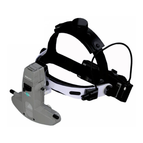
5. Setting up and using the All Pupil II Description of the Product A Headband Size Adjuster I Brow Bar B Headband Height Adjuster J Interpupillary Distance Setting Control C Cushioned Padded Liners K Mirror Angle Control D Aperture Control Lever L Optics Hinge Adjuster E Headband Dimmer Switch M Filter Selector Bar F Brow Bar Adjuster G Front Window H Binocular Block Home Back... -
Page 10: Headband Adjustment
5. Setting up and using the All Pupil II Headband Adjustment Comfortable Fit Adjust the Height and Size Adjusters (A and B) so that the indirect is supported comfortably, as shown in figs 1 and 2. Ophthalmoscope Angle Alignment fig.1 fig.2 Position the Brow Bar (I) such that the Binocular Block (H) is set on the optical axis. The Brow Bar (I) may be correctly positioned by loosening the Brow Bar Adjusters (F). When in the correct position secure by tightening (F) as shown in fig 3. Position the All Pupil II as close to the eyes as possible for maximum field as shown in fig 4. by using the Optics Hinge Adjuster (L). fig.3 fig.4 Home Back Next... -
Page 11: Interpupillary Distance Setting Control
5. Setting up and using the All Pupil II Interpupillary Distance Setting Control (J) Mirror Angle Control (K) Because the eyes are dissociated, particular care must be taken The light is positioned vertically into the upper two thirds of the to ensure the optics (eyepieces) are set properly in front of each field of view by rotating the spindle (K) located on either side of eye. the binocular block. Always set the Aperture Control Lever (D) to the large light patch for this exercise. Place an object, perhaps the thumb, approximately 40cm from the face and centre it horizontally in the light patch. Then, close one eye. Using the thumb and forefinger of the opposite hand, slide the Interpupillary Distance Setting Control (J) of the open Head Dimmer Switch (E) eye (located directly under each eyepiece) so that your object moves into the centre of the field, keeping the object in the Turn the illumination on by rotating the headband dimmer centre of the light patch. Repeat for the other eye. switch (E) in an anti clockwise direction. Obtaining a Fused Image... -
Page 12: Setting The Aperture
5. Setting up and using the All Pupil II Aperture Control Lever (D) Large The large, round homogenous patch is suitable for routine The Aperture Control Lever (D) changes the aperture size to examinations through fully dilated pupils view through large, medium and small pupils. Intermediate Select either the large, intermediate or small aperture by Select either the large, intermediate or small aperture by The intermediate patch is designed to reduce reflections The intermediate patch is designed to reduce reflections adjusting lever from left to right - small - intermediate - large. adjusting lever from left to right - small - intermediate - large. when entering a partially or poorly dilated pupil (3mm). It when entering a partially or poorly dilated pupil (3mm). It is also ideal for closer inspection of particular fundal areas. is also ideal for closer inspection of particular fundal areas. Small Small This light patch is ideal for small, undilated pupils. This light patch is ideal for small, undilated pupils. Home Back Next... -
Page 13: Selecting Filters
5. Setting up and using the All Pupil II Filter Selector Bar (M) Red Free Filter This filter reduces red light, so blood will appear black, The All Pupil II has two selectable filters built in to the silhouetted against a dark background. head unit. Select the appropriate filter by sliding the Filter Selector Bar (M) either left or right from its mid position. Diffuser This unique extra wide beam of diffused light permits a The Filter Selector Bar is marked with dots to indicate in more relaxed technique during more challenging fundus more relaxed technique during more challenging fundus which direction to slide it for each filter. which direction to slide it for each filter. which direction to slide it for each filter. examinations. Beginners may also find this aperture examinations. Beginners may also find this aperture particularly helpful since, in order to achieve a full lens particularly helpful since, in order to achieve a full lens image, the alignment between the headset, the image, the alignment between the headset, the condensing lens and the pupil is not as critical as with the condensing lens and the pupil is not as critical as with the conventional beam. conventional beam. The instrument provides protection from UV/IR. -
Page 14: Wireless Chargers
6. Wireless chargers – power supply assembly Set Plug Replace the blanking plate with the appropriate mains plug adaptor if required, or use IEC 60320 TYPE 7 connector (not supplied). IEC 60320 TYPE 7 connector Home Back Next... -
Page 15: Standard Lithium
6. Wireless chargers – Standard Lithium Inserting/replacing the Battery Pack 1. Release battery by pressing release button as shown and lift battery pack from cradle. 2. To insert new battery pack, place in cradle until fully engaged. Press release button Home Back Next... -
Page 16: Slimline Lithium Ion
6. Wireless chargers – Slimline Lithium-ion Inserting/replacing the Battery Pack 1. Release battery by pressing release button as shown and lift battery pack from cradle. 2. To insert new battery pack, place in cradle until fully engaged. Home Back Next... -
Page 17: Power Supply
Remove the blanking plate 6. Wireless chargers Connect to charging/docking station Charging 1. Replace the blanking plate with the Replace with appropriate appropriate mains plug adapter, and mains plug connect plug on cable to power input adapter Power Supply socket on charger. Spare battery Switch on your Lithium Charger by plugging it into a mains outlet. Press release Charging/ button and docking station push up 2. Place your spare battery pack or headset into your Lithium Power supply Charger as shown. inlet Spare battery Charging/ docking station Home Home Back Back Next Next... - Page 18 Charging spare battery 6. Wireless chargers Charging battery on headband Headband Battery Holder Slimline Lithium ion Flashing LED – Battery requires charging. Charging Station No indicator – Battery is fully charged. Flashing indicator – Top up Charge. Solid indicator – Rapid Charge. The battery pack can be used at any time Charging spare battery only during the charging cycle and will Standard Charging battery on automatically resume charging when Lithium headband battery pack is placed back in the charger. Direction arrow on charger indicates which battery is being charged. Home Home Back Back Next Next...
- Page 19 6. Wireless chargers Charging Cycle - Standard Lithium The battery attached to the indirect will take approximately 2 hours to fully charge. The battery will last approximately 2 hours on full power. The spare battery will take 4 hours to charge. Charging Cycle - Slimline Lithium ion The battery attached to the indirect will take approximately 1½ hours to fully charge. The battery will last approximately 1 hour on full power. The spare battery will take 1½ hours to charge. Home Back Next...
-
Page 20: Wall Mounting
6. Wireless chargers – wall mounting Use template document provided to mark position of charger and drill holes. Home Back Next... - Page 21 6. Wireless chargers – wall mounting Caution Home Back Next...
-
Page 22: Smartpack And Wallpack
7. SmartPack and WallPack Parts List A Hex Key B Screws C Screws D Wall Plugs E Base Cap F Wall Mount G Adhesive Pads H Rechargeable battery Part No. EP39 22079 I Body J Power Supply K Australian Plug L UK Plug M Euro Plug N USA Plug Home Back Next... -
Page 23: Power Conversion
7. SmartPack and WallPack Set Plug Power Conversion Assemble the power supply as per the instructions in section 6. Convert to either WallPack or SmartPack by following the illustration below. IEC 60320 TYPE 7 connector Home Back Next... -
Page 24: Wall Mounting / Charging
7. SmartPack and WallPack 30 mm Fixing the Wall Mount Use the wall plugs and screws to mount the wall pack unit, attach the adhesive pads to the side of the case. Ø 6 x 50 mm Connection Insert the connectors into the sockets Charge Time as shown. Before connecting ensure Charge the battery for that both the 12 - 14 hours before initial use. dimmer control Note: The unit becomes warm and mains outlet when charging, this is normal. are switched off. Recharging may take place while indirect is in use. Normal battery life is 1.5 to 5 hours depending on setting with a recharge time of two hours or on continuous trickle. Home Back Next... -
Page 25: Led Displays
7. SmartPack and WallPack Power Supply Battery LED Displays Insert or remove the indirect plug or switch the indirect off/on. Slow Pulse Power Supply Mains Fast Pulse • Switch the indirect ON/OFF • Insert or remove the mains plug LED On • Place on or off the cradle switch • Green LED illuminates when indirect is on LED Off Charging Trickle Charging In use Battery low Home Back Next... -
Page 26: Led/Bulb Replacement
8. LED/bulb replacement All Pupil II LED Caution: All PupiI II bulbs can be replaced with Bulbs / LED’s can reach high temperatures in use – allow an LED light source if required. Follow to cool before handling fitting instructions as for bulbs, and as shown below: Use only genuine Keeler approved parts and accessories or device safety and performance may be compromised Disconnect the instrument from the electrical supply. Remove the bulb / LED from the back of the instrument and insert the replacement, ensuring that the bulb / LED key is aligned with the aperture and securely pushed in. After removal of the After removal of the bulb / LED do not touch the bulb / LED do not touch the bulb / LED contacts and bulb / LED contacts and the patient simultaneously the patient simultaneously For further details see section 12. Home Back Next... -
Page 27: Cleaning Instructions
9. Cleaning • Only manual non-immersion cleaning as described should be used for this instrument • Do not autoclave or immerse in cleaning fluids Always disconnect power supply from source before cleaning a Wipe the external surface with a clean absorbent, non- shedding cloth dampened with a water / detergent solution (2% detergent by volume) or water / isopropyl alcohol solution (70% IPA by volume). Avoid optical surfaces b Ensure that excess solution does not enter the instrument. Use caution to ensure cloth is not saturated with solution c Surfaces must be carefully hand-dried using a clean non- shedding cloth d Safely dispose of used cleaning materials Home Back Next... -
Page 28: Specifications And Electrical Ratings
10. Specifications and electrical ratings All Pupil II Input mains data: 100-240V – 50/60Hz Power supply rating: 12V : 2.5amps Operation: Continuous Classification: Class II equipment Type B protection against shock Transport, storage and operating conditions Transport Storage Operation Temperature -40°C -10°C +10°C range to +70°C to +55°C to +35°C Relative 10% to 95% 10% to 95% 30% to 75% humidity API II LED... -
Page 29: Annex I - Emc Statement And Guidelines
11. Annex I – EMC statement and guidelines The Keeler All Pupil II Indirect Ophthalmosope is a medical electrical instrument. The instrument requires special care concerning electromagnetic compatibility (EMC). This section describes the suitability in terms of electromagnetic compatibility of this instrument. When installing or using this instrument, please read carefully and observe what is described here. Portable or mobile-type radio frequency communication units may have an adverse effect on this instrument, resulting in malfunctioning. Note: The API II LED is considered to be inherently EMC benign (1) however when used as intended in conjunction with the All Pupil II Indirect Ophthalmoscope, the EMC requirements for the API II apply, and must be adhered to. (1) Refer to section 1.1.4 of the guide for the EMC Directive 2004/108/EC, published 21st May 2007. Home Back Next... - Page 30 11. Annex I – EMC statement and guidelines Guidance and manufacturer’s declaration – electromagnetic immunity The Keeler All Pupil II is intended for use in the electromagnetic environment specified below. The customer or the user should assure that it is used in such an environment. Immunity test IEC 60601 Test level Compliance level Electromagnetic environment - guidance Electrostatic ± 6 kV contact ± 6 kV contact Floors should be wood, concrete or ceramic tile. discharge (ESD). ± 8 kV air ± 8 kV air If floors are covered with synthetic material, the relative IEC 61000-4-2 humidity should be at least 30%. Electrical fast ± 2 kV for power supply lines ± 2 kV for power supply lines Mains power quality should be that of a typical commercial transient/burst. ± 1 kV for input/output lines or hospital environment. IEC 61000-4-4 Surge. ± 1 kV line(s) to line(s) ± 1 kV line(s) to line(s) Mains power quality should be that of a typical commercial IEC 61000-4-5 ± 2 kV line(s) to earth or hospital environment.
- Page 31 11. Annex I – EMC statement and guidelines Guidance and manufacturer’s declaration – electromagnetic emissions The Keeler All Pupil II is intended for use in the electromagnetic environment specified below. The customer or user should assure that it is used in such an environment. Emissions test Compliance Electromagnetic environment - guidance RF emissions Group 1 The Keeler All Pupil II uses RF energy only for its internal function. CISPR 11 Therefore, its RF emissions are very low and are not likely to cause any interference in nearby electronic equipment. Charger only RF emissions Class B The Keeler All Pupil II is suitable for use in all establishments, including CISPR 11 domestic establishments and those directly connected to the public low- voltage power supply network that supplies buildings used for domestic Harmonic emissions Class A purposes. IEC 61000-3-2 Voltage fluctuations / Complies flicker emissions IEC 61000-3-3 Indirect RF emissions Complies The Keeler All Pupil II is not suitable for interconnection with other Ophthalmoscope CISPR 15 equipment.
- Page 32 Electromagnetic environment - guidance Portable and mobile RF communications equipment should be used no closer to any part of the Keeler All Pupil II, including cables, than the recommended separation distances calculated from the equation applicable to the frequency of the transmitter. Recommended separation distance Conducted RF 3 Vrms d = 1.2 √ p IEC 61000-4-6 150 kHz to 80 MHz d = 1.2 √ p 80MHz to 800 MHz Radiated RF 3 V/m 3 V/m d = 2.3 √ p 800MHz to 2.5GHz IEC 61000-4-3 80MHz to 2.5GHz Where p is the maximum output power rating of the transmitter in watts(W) according to the transmitter manufacturer and d is the recommended separation distance in metres(m). Field strengths from fixed RF transmitters, as determined by an electromagnetic site survey¹, should be less than the compliance level in each frequency range.² Interference may occur in the vicinity of equipment marked with the following symbol: Note 1 At 80MHz and 800MHz, the higher frequency range applies. Note 2 These guide lines may not apply in all situations. Electromagnetic propagation is affected by absorption and reflection from structures, objects and people. ¹ Field strengths from fixed transmitters, such as base stations ( cellular / cordless) telephones and land mobile radios, amateur radio, AM and FM radio broadcast and TV broadcast cannot be predicted theoretically with accuracy. To assess the electromagnetic environment due to fixed RF transmitters, an electromagnetic site survey should be considered. If the measured field strength in the location in which the Keeler All Pupil II is used exceeds the applicable RF compliance level above, the Keeler All Pupil II should be observed to verify normal operation. If abnormal performance is observed, additional measures may be necessary, such as re-orientating or relocating the Keeler All Pupil II. Home Back Next ² Over the frequency range 150kHz to 80 MHz, field strengths should be less than 3 V/m.
- Page 33 11. Annex I – EMC statement and guidelines Recommended separation distances between portable and mobile RF communications equipment and the Keeler All Pupil II The Keeler All Pupil II is intended for the use in an electromagnetic environment in which radiated RF disturbances are controlled. The customer or the user of the Keeler All Pupil II can help prevent electromagnetic interference by maintaining a minimum distance between portable and mobile RF communications equipment (transmitters) and the Keeler All Pupil II as recommended below, according to the maximum output power of the communications equipment. Rated maximum Separation distance according to frequency of transmitter output power of transmitter 150 kHz to 80MHz 80MHz to 800MHz 800MHz to 2.5GHz d = 1.2√ p d = 1.2√ p d = 2.3√ p 0.01 0.12 0.12 0.23 0.37 0.37 0.74 For transmitters rated at a maximum output power not listed above, the recommended separation distance d in metres (m) can be determined using the equation applicable to the frequency of the transmitter, where p is the maximum output power rating of the transmitter in watts (W) according to the transmitter manufacturer. Note 1 At 80MHz and 800MHz, the higher frequency range applies. Note 2 These guide lines may not apply in all situations. Electromagnetic propagation is affected by absorption and reflection from structures, objects and people. Home Back...
-
Page 34: Spare Parts And Accessories
12. Spare parts and accessories The following accessories are typical of those supplied in the kits Wireless, with standard battery and charger (e.g. 1204-P-3041) as indicated: As for 1204-P-3038 example, without 1945-P-1001, but plus: Part Number Description API Bulb version, wired (e.g. 1204-P-3038) EP39-22706 Wall pad Part Number Description EP59-49013 Wall mount template EP79-06498 Rawlbloc wall plug (qty 2) EP09-00755 API II case 1012-P-5110 API II halogen bulb EP29-32777 Power supply 1941-P-5334 Standard charger EP39-53748 Eye Lens Plano (qty 2) EP39-53799 Rubber Eye Cap (qty 2) The following items are available in addition to the accessories EP79-70059... -
Page 35: Api Ii Led
12. Spare parts and accessories API II LED The API II LED is a replacement light source for the All Pupil II Indirect Ophthalmoscope. Follow the guidance in section 8 for fitting. Home Back Next... -
Page 36: Teaching Mirror
12. Spare parts and accessories Teaching mirror To remove, slide the teaching mirror to the right of the pin and return to its case leaving mounting bar in position (A) Remove the screws from To make the teaching mirror Non-Removable for security the panel beneath the purposes proceed as follows: front window with the Remove the screws as in step (A). Position the mounting bar and screwdriver supplied. replace the screw on left side only. Fit the teaching mirror as in step (B). Fold the Teaching Mirror down and slide it to the right to reveal fixing hole. Then secure the (B) Fit the mounting bar with mounting bar with the special the pin pointing to the washer and pan head screw right and secure with provided. screws removed in step (A). Return the teaching mirror to Slide the teaching mirror its central position. onto the pin on the mounting bar. The teaching mirror can now be demounted only by removing The teaching mirror can now be the screw. Retain the screwdriver swivelled up and down. for future use. Home Back Next... -
Page 37: Eyepiece Caps
12. Spare parts and accessories Eyepiece Caps These are available in the following colours: Red (EP39-25050), Light Blue (EP39-25069) and Eyepiece caps are provided to protect spectacles and have rubber Dark Blue (EP39-25077) surrounds to prevent scratching. To use, simply fit over the eyepieces. Replacements are available from the distributor (Part Do not use ExpressiOn Clip on Covers during surgical No. EP39-53799). For further details please refer to the accessory procedures lists on page 34. Plano Lenses The Keeler All Pupil II is supplied with +2D lenses as standard. Plano lenses, if preferred, are also available from the distributor. These are included in certain API II kits. For further details please refer to the accessory lists on page 34. ExpressiOn Clip on Covers A range of different colour front covers are available to fit over your Indirect. To fit the cover, simply push on until the small clips on the side and underneath engage with the slots in the main moulding as shown in diagram. Please ensure the cover is fitted correctly (as per instructions) before use. See image to right. Home Home Back Next... -
Page 38: Warranty
13. Warranty No user serviceable parts – all preventative maintenance and servicing must only be performed by authorised Keeler representatives. Your Keeler product is guaranteed for 3 years and will be replaced, or repaired free of charge subject to the following:- • Any fault due to faulty manufacture • The instrument and accessories have been used in compliance with these instructions • Proof of purchase accompanies any claim Please note: The API II LED is guaranteed for 5 years. Batteries are covered by this warranty statement for 1 year only. Home Back Next... -
Page 39: Contact And Disposal Information
14. Contact and disposal information Keeler Limited Keeler Instruments Inc Clewer Hill Road 3222 Phoenixville Pike Windsor Building #50 Berkshire SL4 4AA Malvern, PA 19355 England Freephone: 0800 521 251 Toll Free: 1 800 523 5620 Tel: +44 (0)1753 857177...
Need help?
Do you have a question about the All Pupil II and is the answer not in the manual?
Questions and answers