Table of Contents
Advertisement
Advertisement
Table of Contents

Subscribe to Our Youtube Channel
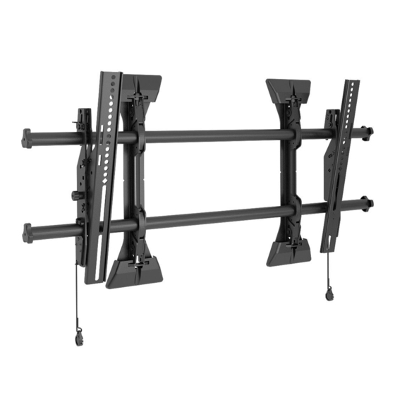
Summary of Contents for CHIEF MTM1U
- Page 1 I N S T A L L A T I O N I N S T R U C T I O N S MTM1U MSM1U LSM1U LTM1U FUSION HEIGHT ADJUST FLAT PANEL MOUNTS Spanish Product Description German Product Description Portuguese Product Description Italian Product Description MSM1U / MTM1U / LSM1U / LTM1U...
-
Page 2: Important Safety Instructions
MSM1U/ claim that the information contained herein covers all details, MTM1U does not exceed 125 lbs (56.7 kg); OR 200 lbs (90.7 conditions or variations, nor does it provide for every possible kg) for the LSM1U/LTM1U. -
Page 3: Installation Instructions
Installation Instructions MSM1U / MTM1U / LSM1U / LTM1U DIMENSIONS MSM1U 6.00 152.4 RAILS CAN BE SLID LEFT OR RIGHT FOR OFFSET MAXIMUM MOUNTING PATTERN IS 22.7" (576 mm) WITHOUT REVERSING UPRIGHTS DIMENSIONS: INCHES MAXIMUM MOUNTING PATTERN IS 25.3" (642 mm) WITH REVERSING UPRIGHTS... - Page 4 MSM1U / MTM1U / LSM1U / LTM1U Installation Instructions DIMENSIONS - continued LSM1U DIMENSIONS: INCHES [MILLIMETERS] LTM1U DIMENSIONS: INCHES [MILLIMETERS]...
- Page 5 Installation Instructions MSM1U / MTM1U / LSM1U / LTM1U LEGEND Tighten Fastener Pencil Mark Apretar elemento de fijación Marcar con lápiz Befestigungsteil festziehen Stiftmarkierung Apertar fixador Marcar com lápis Serrare il fissaggio Segno a matita Bevestiging vastdraaien Potloodmerkteken Serrez les fixations...
-
Page 6: Tools Required For Installation
MSM1U / MTM1U / LSM1U / LTM1U Installation Instructions TOOLS REQUIRED FOR INSTALLATION 3/16" x 10" 1/8" 7/32" (5.5mm) Wood Stud (included) (included) 3/8" (9.5mm) Concrete PARTS Universal Hardware Kit H (4) G (4) F (4) E (4) C (4) -
Page 7: Installing To A Wood Stud Wall
Drill one 7/32" (5.5mm) pilot hole in each stud. be mounted to a bare 8" concrete, 8"x8"x16" concrete block; or 2" x 4" wood studs (16" on center for MSM1U/MTM1U, and 16" Partially install two 5/16 x 2-1/2" flanged lag bolts (N) into or 24"... - Page 8 MSM1U / MTM1U / LSM1U / LTM1U Installation Instructions Installing to a Concrete Wall 12. Drill 3/8" x 3-1/2" (9.5mm x 88.9mm) pilot holes at markings for lower mounting holes. (See Figure 3) Determine the center of the TV screen, and where it should 13.
- Page 9 The location of the left and right interface brackets (Y and Z or AA and BB) may be switched, with the knobs on the MTM1U/LTM1U interface brackets (AA and BB) facing the Pull cord inside of the mount. (See Figure 7)
- Page 10 MSM1U / MTM1U / LSM1U / LTM1U Installation Instructions If necessary, the tilt interface bracket knobs may be NOTE: NEVER place both interface brackets (Y and Z or AA switched to allow the interface brackets (AA and BB) to be and BB) to one side of the wall mount center line! (See reversed.
- Page 11 Installation Instructions MSM1U / MTM1U / LSM1U / LTM1U Hang screen onto the top rail of the mount (CC). (See Figure 11) • MSM1U / LSM1U: Hang top hook of interface brackets (Y and Z) onto the top rail of the mount (CC).
- Page 12 Do NOT allow both interface brackets (Y and Z or AA and BB) to be located on same side of wall bracket. (See Figure 10) (MTM1U / LTM1U only) Move latch on top of interface brackets to CLOSED position. (See Figure 14) Interface...
- Page 13 Installation Instructions MSM1U / MTM1U / LSM1U / LTM1U Locking Screen Interface Brackets (Optional) Locking Mount (Optional) Lock screen interface brackets onto mount rails using one Add padlock (not included) to interface bracket to complete 3/8-16 x 3/4" set screw (U) on each interface bracket. (See security.
- Page 14 MSM1U / MTM1U / LSM1U / LTM1U Installation Instructions...
- Page 15 Installation Instructions MSM1U / MTM1U / LSM1U / LTM1U...
- Page 16 MSM1U / MTM1U / LSM1U / LTM1U Installation Instructions USA/International A 6436 City West Parkway, Eden Prairie, MN 55344 P 800.582.6480 / 952.225.6000 F 877.894.6918 / 952.894.6918 Europe A Franklinstraat 14, 6003 DK Weert, Netherlands P +31 (0) 495 580 852...


Need help?
Do you have a question about the MTM1U and is the answer not in the manual?
Questions and answers