JVC DT-V1710CG Service Manual
Multi-format monitor
Hide thumbs
Also See for DT-V1710CG:
- Instructions manual (228 pages) ,
- Instructions manual (64 pages) ,
- Instructions manual (28 pages)
Table of Contents
Advertisement
SERVICE MANUAL
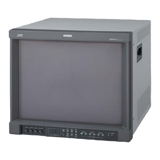
MULTI-FORMAT MONITOR
DT-V1710CG
DT-V1710CG
For the specifications, adjustments or part lists of optional board IF-C01PNG (NTSC/PAL
video input card) and IF-C01COMG (Component/RGB input card), refer to service manual
DT-V1700CG
(No.51899).
/E
1. PRECAUTIONS .......................................................................................................................................... 1-3
2. SPECIFIC SERVICE INSTRUCTIONS .......................................................................................................... 1-4
3. DISASSEMBLY ........................................................................................................................................... 1-5
4. ADJUSTEMNT .......................................................................................................................................... 1-13
5. TROUBLE SHOOTING .............................................................................................................................. 1-73
COPYRIGHT © 2003 VICTOR COMPANY OF JAPAN, LTD.
TABLE OF CONTENTS
BASIC CHASSIS
R1
/U
/E
No. 52152
2003/9
Advertisement
Table of Contents

Related Manuals for JVC DT-V1710CG


Summary of Contents for JVC DT-V1710CG
- Page 1 SERVICE MANUAL MULTI-FORMAT MONITOR BASIC CHASSIS DT-V1710CG DT-V1710CG For the specifications, adjustments or part lists of optional board IF-C01PNG (NTSC/PAL video input card) and IF-C01COMG (Component/RGB input card), refer to service manual DT-V1700CG (No.51899). TABLE OF CONTENTS 1. PRECAUTIONS ............................1-3 2.
-
Page 2: Specifications
SPECIFICATIONS Items Contents Type Multi-format monitor Picture Tube 17” Flat 33cm(13”) × 25cm(9-7/8”) / 41cm(16-1/4”) [measured diagonally] Effective Screen Size Input Signal Frequency Horizontal : 15kHz/27kHz – 45kHz Vertical : 50Hz – 80Hz Video Band Component : 25MHz (-3dB) Video (Y/C) : 8MHz (-3dB) Horizontal Resolution 1080/60i : 800 TV lines Video (Y/C) : 600 TV lines... - Page 3 SECTION 1 PRECAUTION 1.1 SAFETY PRECAUTIONS (1) The design of this product contains special hardware, (9) When service is required, observe the original lead dress. many circuits and components specially for safety Extra precaution should be given to assure correct lead dress in the high voltage circuit area.
- Page 4 SPECIFIC SERVICE INSTRUCTIONS 2.1 HOW TO IDENTIFT MODEL Please check the destination and the version of your model by RATING LABEL. ! DT-V1710CG/U [FOR NORTH AMERICA MODEL] INDICATED “DT-V1710CGU” ! DT-V1710CG/E [FOR EUROPE AND ASIA MODELS] INDICATED “DT-V1710CGE” 1-4 (No. 52152)
- Page 5 SECTION 3 DISASSEMBLY 3.1 DISASSEMBLY PROCEDURE 3.1.5 REMOVING THE CRT AND LED PW BOARD • Remove the SLOT PANEL, TOP COVER, REAR PANEL, CAUTION : BOTTOM COVER, SLOT CHASSIS and CHASSIS BASE. • Some parts are active even after the main power switch is (1) Remove the four screws [14] and remove the SIDE set to OFF.
- Page 6 TOP COVER MOTHER PWB SIGNAL PWB REMOTE PWB JOINT BRACKET LED PWB SLOT CHASSIS SIDE BRACKET PB BRACKET HV CONTROL MODULE PWB S. CORRECTION CRT SOCKET CHASSIS BASE SIDE BRACKET SUB DEF MODULE PWB SPEAKER CONTROL MAIN PWB BASE REAR PANEL FRONT VR PWB BOTTOM COVER FRONT CONTROL PWB...
- Page 7 3.2 DEMAGNETIZATION PROCEDURE 3.2.1 CAUTION (1) Use a rod-type demagnetization coil. NOTE: Never use a ring-shaped demagnetization coil. (2) Keep the demagnetization coil at a distance of more than 1.5 cm from the CRT screen and the main unit during use. (3) When demagnetizing the CRT screen, hold the demagnetization coil perpendicularly to the CRT screen.
- Page 8 3.2.2 DEMAGNETIZING THE CRT SCREEN (1) While holding the power button of the demagnetization coil, move it to approach the CRT screen area that has color irregularities. (Keep the demagnetization coil at a distance of more than 1.5 cm from the screen.) (2) From the area with the colour irregularities, move the demagnetization coil as if drawing a spiral toward the center of the CRT screen.
- Page 9 3.3 MEMORY IC REPLACEMENT 3.3.1 MEMORY IC The unit incorporates a nonvolatile Memory IC, which stores data on the video and deflection systems, etc. When it is replaced with an IC without the data stored in it, the set may malfunction or the video may become abnormal when the unit is turned on.
- Page 10 3.3.3 FACTORY SETTING VALUE ! INITIAL SETTING VALUE TABLE [SET-UP MENU] Setting Item Data / Variable range Initial setting value Remarks FUNCTION SETTING COLOR SYSTEM AUTO / NTSC / PAL AUTO Apply the NTSC/PAL signal AUTO INPUT ON/OFF Apply the HD SDI/SDI signal SYNC SELECT INT.
- Page 11 ! INITIAL SETTING VALUE TABLE [MAIN MENU] Setting Item Data / Variable range Initial setting value APERTURE CONTROL LEVEL 00 – 10 CONTROL FREQ. HIGH / LOW / OFF HIGH SLOT CONDITION Type of boards installed in the rear panel slots. INPUT A –...
- Page 12 REPLACEMENT OF CHIP COMPONENT 3.4.1 CAUTIONS (1) Avoid heating for more than 3 seconds. (2) Do not rub the electrodes and the resist parts of the pattern. (3) When removing a chip part, melt the solder adequately. (4) Do not reuse a chip part after removing it. 3.4.2 SOLDERING IRON (1) Use a high insulation soldering iron with a thin pointed end of it.
- Page 13 SECTION 4 ADJUSTMENT 4.1 ADJUSTMENT PRECUTION (1) Make sure that connection is correctly mode AC to AC power souce. (2) Warm run the unit and measuring tools sufficiently (at least 30 minutes). (3) Perform all adjustments based on the initial values. There is no problem if the result of an adjustment performed by observing the screen is different from the initial value.
- Page 14 4.4 MEASURING INSTRUMENTS AND FIXTURES (1) DC voltmeter ( or digital voltmeter) (2) Oscilloscope (3) Color analyzer (colour temperature meter) (4) High-voltage voltmeter (5) Signal generator (Should be compatible with the following signal specifications.) (6) Scale (made of non-metallic material) (7) IF-C01PNG (NTSC/PAL Video Input Card) (8) IF-C01COMG (Component/RGB Input Card) Fromats of Signal Used in Adjustments...
- Page 15 4.6 TIMING CHART OF SIGNALS REQUIRED FOR ADJUSTMENTS Generate the signals required for adjustments with a programmable signal generator by referring to the following figure. Display area Front porch Sync Back porch Total period Signal NTSC(14.3) 480/60i 576/50i 480/60p 576/50p 720/50p 720/60p 1080/24psF 1080/50i 1080/60i Resolution(Horizontal)
- Page 16 4.7 ADJUSTMENT LOCATIONS S. CORRECTION PWB (SOLDER SIDE) CRT SOCKET PWB (SOLDER SIDE) CN0RD CN00R FRONT TP-47B TP-47R TP-47G TP-GND CN010 CN011 MAIN PWB FRONT S. CORRECTION PWB CN011 HV CONTROL MODULE PWB CN005 CN010 CN001 CN004 SUB DEF MODULE PWB CN002 CN003 F901...
- Page 17 4.8 BASIC OPERATIONS OF SERVICE MENU 4.8.1 SERVICE MENU ITEMS The service menu is roughly classified according to setup and adjustments, and is divided into the following items. Do not alter the values of unnecessary items. SIGNAL BLOCK Adjustments of the contrast, brightness, chroma and phase. WHITE BALANCE BLOCK Adjustments of the white balance.
- Page 18 2. Setting the Service Menu items (1) With the Service Menu displayed, press the key to < > SIGNAL BLOCK select the item to be adjusted, then press the VOL+ SA : VIDEO -NTSC ) key to enter the submenu for the item. SB : Y/C -NTSC SC : VIDEO -PAL...
-
Page 19: Service Menu
4.8.3 SERVICE MENU FLOW CHART [SERVICE MENU] [SIGNAL BLOCK 1/3] [SIGNAL BLOCK 2/3] [SIGNAL BLOCK 3/3] < > < > < > SIGNAL BLOCK SIGNAL BLOCK SIGNAL BLOCK SIGNAL BLOCK SA : VIDEO -NTSC SI : COMP. -1080/60i SQ : ASPECT WHITE BALANCE BLOCK SB : Y/C -NTSC... - Page 20 [SERVICE MENU] [CPU BLOCK] [CA : MENU] < > CPU BLOCK XXXXX X XXXXX SIGNAL BLOCK CA : MENU XXXX WHITE BALANCE BLOCK CB : SIGNAL XXXX DEFLECTION BLOCK CC : SETTING XXXX CPU BLOCK CD : DEFLECTION DIAGNOSIS CE : OSD etc UPC1884 ADJ.
- Page 21 4.9 INITIAL SETTING VALUE OF SERVICE MENU Note that the following values other than the fixed values should simply be used as references during adjustments. Their correct values may be variable depending on individual units. [SIGNAL BLOCK] Setting item Variable range Initial setting value SA [VIDEO NTSC] S[A01]...
- Page 22 Setting item Variable range Initial setting value S[D04] PHASE -064 ~ +063 S[D05] APERTURE -064 ~ +063 S[D06] BRIGHT LOW -128 ~ +127 S[D07] Y DL 000/001 000 (Fixed value) S[D08] R-Y PHASE 000 ~ 003 000 (Fixed value) S[D09] R/B GAIN 000 ~ 003 002 (Fixed value)
- Page 23 Setting item Variable range Initial setting value SH [COMP. 576/50p] S[H01] CONTRAST -064 ~ +063 +018 S[H02] BRIGHT HIGH -128 ~ +127 S[H03] CHROMA -064 ~ +063 S[H04] PHASE -064 ~ +063 S[H05] APERTURE -064 ~ +063 S[H06] BRIGHT LOW -128 ~ +127 S[H07] Y DL...
- Page 24 Setting item Variable range Initial setting value S[K07] Y DL 000/001 000 (Fixed value) S[K08] R-Y PHASE 000 ~ 003 000 (Fixed value) S[K09] R/B GAIN 000 ~ 003 003 (Fixed value) S[K10] G-Y PHASE 000 ~ 003 002 (Fixed value) S[K11] G/B GAIN 000 ~ 003...
- Page 25 Setting item Variable range Initial setting value S[O02] BRIGHT HIGH -128 ~ +127 -070 S[O03] BRIGHT LOW -128 ~ +127 -070 SP [SCAN UNDER] S[P01] NTSC-COMPOS. CONTRAST -064 ~ +063 -007 S[P02] NTSC-COMPOS. BRIGHT HIGH -128 ~ +127 S[P03] NTSC-COMPOS. BRIGHT LOW -128 ~ +127 S[P04] NTSC-Y/C CONTRAST...
- Page 26 Setting item Variable range Initial setting value S[P41] 720/50p BRIGHT HIGH -128 ~ +127 S[P42] 720/50p BRIGHT LOW -128 ~ +127 SQ [ASPECT] S[Q01] NTSC-COMPOS. OVERSCAN CONTRAST -064 ~ +063 -011 S[Q02] NTSC-COMPOS. OVERSCAN BRIGHT HIGH -128 ~ +127 S[Q03] NTSC-COMPOS.
- Page 27 Setting item Variable range Initial setting value S[Q41] 480p UNDERSCAN BRIGHT HIGH -128 ~ +127 S[Q42] 480p UNDERSCAN BRIGHT LOW -128 ~ +127 S[Q43] 576p OVERSCAN CONTRAST -064 ~ +063 -011 S[Q44] 576p OVERSCAN BRIGHT HIGH -128 ~ +127 S[Q45] 576p OVERSCAN BRIGHT LOW -128 ~ +127 S[Q46]...
- Page 28 Setting item Variable range Initial setting value S[S23] 576p ZOOMSCAN BRIGHT HIGH -128 ~ +127 S[S24] 576p ZOOMSCAN BRIGHT LOW -128 ~ +127 S[S25] 1080/60i ZOOMSCAN CONTRAST -064 ~ +063 +009 S[S26] 1080/60i ZOOMSCAN BRIGHT HIGH -128 ~ +127 S[S27] 1080/60i ZOOMSCAN BRIGHT LOW -128 ~ +127 S[S28]...
- Page 29 [WHITE BALANCE BLOCK] Setting item Variable range Initial setting value WA [NTSC(COMPOS.,Y/C) HIGH] W[A01] DRIVE (R) -128 ~ +127 W[A02] DRIVE (G) – W[A03] DRIVE (B) -128 ~ +127 W[A04] CUTOFF (R) -128 ~ +127 W[A05] CUTOFF (G) -128 ~ +127 W[A06] CUTOFF (B) -128 ~ +127...
- Page 30 Setting item Variable range Initial setting value WG [COMP. 480(576)p HIGH] W[G01] DRIVE (R) -128 ~ +127 W[G02] DRIVE (G) – W[G03] DRIVE (B) -128 ~ +127 W[G04] CUTOFF (R) -128 ~ +127 W[G05] CUTOFF (G) -128 ~ +127 W[G06] CUTOFF (B) -128 ~ +127 WH [COMP.
- Page 31 Setting item Variable range Initial setting value WM [COMP. 1080/50i HIGH] W[M01] DRIVE (R) -128 ~ +127 W[M02] DRIVE (G) – W[M03] DRIVE (B) -128 ~ +127 W[M04] CUTOFF (R) -128 ~ +127 W[M05] CUTOFF (G) -128 ~ +127 W[M06] CUTOFF (B) -128 ~ +127 WN [COMP.
- Page 32 Setting item Variable range Initial setting value WS [COMP. 720/50p HIGH] W[S01] DRIVE (R) -128 ~ +127 W[S02] DRIVE (G) – W[S03] DRIVE (B) -128 ~ +127 W[S04] CUTOFF (R) -128 ~ +127 W[S05] CUTOFF (G) -128 ~ +127 W[S06] CUTOFF (B) -128 ~ +127 WT [COMP.
- Page 33 [DEFLECTION BLOCK] Setting item Variable range Initial setting value DA [NTSC(COMPOS.,Y/C) OVER] D[A01] HORIZONTAL SIZE -064 ~ +064 -016 D[A02] VERTICAL SIZE -064 ~ +064 D[A03] HORIZONTAL POSITION -064 ~ +064 +015 D[A04] VERTICAL POSITION -064 ~ +064 D[A05] SIDE PIN DISTORTION -032 ~ +032 +005 D[A06]...
- Page 34 Setting item Variable range Initial setting value D[D03] HORIZONTAL POSITION -064 ~ +064 D[D04] VERTICAL POSITION -064 ~ +064 D[D05] SIDE PIN DISTORTION -032 ~ +032 +001 D[D06] CORNER DISTORTION (W) -032 ~ +032 D[D07] CORNER DISTORTION (S) -032 ~ +032 D[D08] PARALLELOGRAM DISTORTION -032 ~ +032...
- Page 35 Setting item Variable range Initial setting value D[G06] CORNER DISTORTION (W) -032 ~ +032 D[G07] CORNER DISTORTION (S) -032 ~ +032 -002 D[G08] PARALLELOGRAM DISTORTION -032 ~ +032 D[G09] TRAPEZOIDAL DISTORTION -032 ~ +032 -005 D[G10] HORIZONTAL ARC DISTORTION -032 ~ +032 D[G11] VERTICAL LINEARITY (S CORRECTION) -016 ~ +016...
- Page 36 Setting item Variable range Initial setting value D[J09] TRAPEZOIDAL DISTORTION -032 ~ +032 D[J10] HORIZONTAL ARC DISTORTION -032 ~ +032 D[J11] VERTICAL LINEARITY (S CORRECTION) -016 ~ +016 D[J12] VERTICAL LINEARITY (C CORRECTION) -016 ~ +016 +002 DK [576/50p OVER] D[K01] HORIZONTAL SIZE -064 ~ +064...
- Page 37 Setting item Variable range Initial setting value DN [1080/60i UNDER] D[N01] HORIZONTAL SIZE -064 ~ +064 -011 D[N02] VERTICAL SIZE -064 ~ +064 -025 D[N03] HORIZONTAL POSITION -064 ~ +064 D[N04] VERTICAL POSITION -064 ~ +064 +001 D[N05] SIDE PIN DISTORTION -032 ~ +032 +001 D[N06]...
- Page 38 Setting item Variable range Initial setting value D[Q04] VERTICAL POSITION -064 ~ +064 D[Q05] SIDE PIN DISTORTION -032 ~ +032 +015 D[Q06] CORNER DISTORTION (W) -032 ~ +032 D[Q07] CORNER DISTORTION (S) -032 ~ +032 D[Q08] PARALLELOGRAM DISTORTION -032 ~ +032 D[Q09] TRAPEZOIDAL DISTORTION -032 ~ +032...
- Page 39 Setting item Variable range Initial setting value D[T07] CORNER DISTORTION (S) -032 ~ +032 D[T08] PARALLELOGRAM DISTORTION -032 ~ +032 D[T09] TRAPEZOIDAL DISTORTION -032 ~ +032 D[T10] HORIZONTAL ARC DISTORTION -032 ~ +032 D[T11] VERTICAL LINEARITY (S CORRECTION) -016 ~ +016 D[T12] VERTICAL LINEARITY (C CORRECTION) -016 ~ +016...
- Page 40 Setting item Variable range Initial setting value D[W10] HORIZONTAL ARC DISTORTION -032 ~ +032 D[W11] VERTICAL LINEARITY (S CORRECTION) -016 ~ +016 -002 D[W12] VERTICAL LINEARITY (C CORRECTION) -016 ~ +016 -003 DX [720/50p UNDER] D[X01] HORIZONTAL SIZE -064 ~ +064 -015 D[X02] VERTICAL SIZE...
- Page 41 Setting item Variable range Initial setting value D[Y26] 480p OVERSCAN VERTICAL POSITION -064 ~ +064 +001 D[Y27] 480p OVERSCAN SIDE PIN DISTORTION -032 ~ +032 +012 D[Y28] 480p UNDERSCAN VERTICAL SIZE -064 ~ +064 +006 D[Y29] 480p UNDERSCAN VERTICAL POSITION -064 ~ +064 +001 D[Y30]...
- Page 42 Setting item Variable range Initial setting value D[302] VERTICAL SIZE -064 ~ +064 +040 D[303] HORIZONTAL POSITION -064 ~ +064 D[304] VERTICAL POSITION -064 ~ +064 D[305] SIDE PIN DISTORTION -032 ~ +032 -003 [CPU BLOCK] Setting item Variable range Initial setting value CC [SETTING] C[C41]...
- Page 43 4.10 ADJUSTMENT PROCEDURES 4.10.1 SCREEN VOLTAGE COARSE ADJUSTMENT SCREEN VOLTAGE COARSE ADJUSTMENT Measuring Instruments Signal generator (All-black signal, Crosshatch signal) Oscilloscope Card (Slot) Component/RGB Input Card (Slot 1) Test Points Anode of CRT TP-47B, TP-47R, TP-47G [CRT SOCKET PWB] TP-GND [CRT SOCKET PWB] Adjustment Points SCREEN VR [Bottom potentiometer on high-voltage transformer] VR502 (High-voltage VR) [S.CORRECTION PWB]...
- Page 44 4.10.3 X-RAY PROTECTOR ADJUSTMENT/CHECK X-RAY PROTECTOR ADJUSTMENT/CHECK Measuring Instruments Signal generator (All-white signal) High-voltage voltmeter DC voltmeter Card (Slot) Component/RGB Input Card (Slot 1) Test Points Anode of CRT TP-XR, TP-GND [S. CORRECTION PWB] Adjustment Points VR501 (X-Ray Protector Adjustment VR) [S. CORRECTION PWB] VR502 (High-Voltage VR) [S.
- Page 45 4.10.4 HIGH-VOLTAGE ADJUSTMENT HIGH-VOLTAGE ADJUSTMENT Measuring Instruments Signal generator (All-black signal) High-voltage voltmeter Card (Slot) Component/RGB Input Card (Slot 1) Test Points Anode of CRT Adjustment Points VR502 (High-Voltage VR) [S. CORRECTION PWB] Note: Perform the following adjustments after completing the Screen Voltage Coarse adjustment and X-Ray Protector adjustment.
- Page 46 4.10.6 IMAGE ROTATION ADJUSTMENT IMAGE ROTATION ADJUSTMENT Measuring Instruments Signal generator (Size adjustment signal) Card (Slot) Component/RGB Input Card (Slot 1) Test Points Adjustment Points D101 (Rotation), DM04 (Vertical Position) [Service Menu] Notes: • Perform the following adjustments after completing the Screen Voltage Coarse adjustment, High-Voltage, Focus and X-Ray Protector adjustments.
- Page 47 4.10.7 CONVERGENCE ADJUSTMENT CONVERGENCE ADJUSTMENT Measuring Instruments Signal generator (Crosshatch signal with circle pattern) Card (Slot) Component/RGB Input Card (Slot 1) Test Points Adjustment Points VR504 (CONV_H) [S. CORRECTION PWB] VR505 (CONV_V) [S. CORRECTION PWB] Notes: • Perform the following adjustments after completing the Screen Voltage Coarse adjustment, X-Ray Protector, High Voltage and Focus adjustments.
- Page 48 4.10.8 CONTRAST ADJUSTMENTS CONTRAST ADJUSTMENT (HDTV) Measuring Instruments Signal generator (Crosshatch signal) Oscilloscope Card (Slot) Component/RGB Input Card (Slot 1) Test Points TP-47G [CRT SOCKET PWB] TP-GND [CRT SOCKET PWB] Adjustment Points S*01 (Contrast) [Service Menu] Notes: • Perform the following adjustments after completing the Screen Voltage Coarse adjustment.
- Page 49 CONTRAST ADJUSTMENT (SDTV) Measuring Instruments Signal generator (Crosshatch signal) Oscilloscope Card (Slot) Component/RGB Input Card (Slot 1) Test Points TP-47G [CRT SOCKET PWB] TP-GND [CRT SOCKET PWB] Adjustment Points S*01 (Contrast) [Service Menu] Notes: • Perform the following adjustments after completing the 1080/60i signal Contrast adjustment.
- Page 50 CONTRAST ADJUSTMENT (NTSC/PAL VIDEO) Measuring Instruments Signal generator (Crosshatch signal) Oscilloscope Card (Slot) NTSC/PAL Video Input Card (Slot 2) Test Points TP-47G [CRT SOCKET PWB] TP-GND [CRT SOCKET PWB] Adjustment Points S*01 (Contrast) [Service Menu] Notes: • Ensure that the output waveforms from the NTSC/ PAL Video Input Cards are normal before proceeding to the following adjustments.
- Page 51 CONTRAST ADJUSTMENT (NTSC/PAL Y/C) Measuring Instruments Signal generator (Crosshatch signal) Oscilloscope Card (Slot) NTSC/PAL Video Input Card (Slot 2) Test Points TP-47G [CRT SOCKET PWB] TP-GND [CRT SOCKET PWB] Adjustment Points S*01 (Contrast) [Service Menu] Notes: • Ensure that the output waveforms from the NTSC/ PAL Video Input Cards are normal before proceeding to the following adjustments.
- Page 52 4.10.9 CHROMA/PHASE ADJUSTMENTS CHROMA/PHASE ADJUSTMENTS (COMPONENT) Measuring Instruments Signal generator (Color bar signal) Oscilloscope Card (Slot) Component/RGB Input Card (Slot 1) Test Points TP-47B [CRT SOCKET PWB] TP-GND [CRT SOCKET PWB] Adjustment Points S*03 (Chroma), S*04 (Phase) [Service Menu] Notes: •...
- Page 53 CHROMA/PHASE ADJUSTMENTS (NTSC) Measuring Instruments Signal generator (Color bar signal) Oscilloscope Card (Slot) NTSC/PAL Video Input Card (Slot 2) Test Points TP-47B [CRT SOCKET PWB] TP-GND [CRT SOCKET PWB] Adjustment Points S*03 (Chroma), S*04 (Phase) [Service Menu] Notes: • Ensure that the output waveforms from the NTSC/PAL Video Input Cards are normal before proceeding to the following adjustments.
- Page 54 CHROMA ADJUSTMENTS (PAL) Measuring Instruments Signal generator (Color bar signal) Oscilloscope Card (Slot) NTSC/PAL Video Input Card (Slot 2) Test Points TP-47B [CRT SOCKET PWB] TP-GND [CRT SOCKET PWB] Adjustment Points S*03 (Chroma) [Service Menu] Notes: • Ensure that the output waveforms from the NTSC/PAL Video Input Cards are normal before proceeding to the following adjustments.
- Page 55 4.10.10 DEFLECTION SYSTEM ADJUSTMENTS HORIZONTAL/VERTICAL IMAGE POSITION, IMAGE AMPLITUDE AND IMAGE DISTORTION ADJUSTMENTS (HDTV OVERSCAN MODE) Measuring Instruments Signal generator (Size adjustment signal, Crosshatch signal) Card (Slot) Component/RGB Input Card (Slot 1) Test Points Adjustment Points D*01 (Horizontal Size), D*02 (Vertical Size), D*03 (Horizontal Position), D*04 (Vertical Position), D*05 (Side Pin Distortion), D*06 (Corner Distortion (W)), D*07 (Corner Distortion (S)), D*08 (Parallelogram Distortion), D*09 (Trapezoidal Distortion), D*10 (Horizontal Arc Distortion), D*11 (Vertical Linearity (S Correction)), D*12 (Vertical Linearity (C Correction)) [Service Menu]...
- Page 56 HORIZONTAL/VERTICAL IMAGE POSITION, IMAGE AMPLITUDE AND IMAGE DISTORTION ADJUSTMENTS (HDTV UNDERSCAN MODE) Measuring Instruments Signal generator (Size adjustment signal, Crosshatch signal) Card (Slot) Component/RGB Input Card (Slot 1) Test Points Adjustment Points D*01 (Horizontal Size), D*02 (Vertical Size), D*03 (Horizontal Position), D*04 (Vertical Position), D*05 (Side Pin Distortion), D*06 (Corner Distortion (W)), D*07 (Corner Distortion (S)), D*08 (Parallelogram Distortion), D*09 (Trapezoidal Distortion), D*10 (Horizontal Arc Distortion), D*11 (Vertical Linearity (S Correction)), D*12 (Vertical Linearity (C Correction)) [Service Menu]...
- Page 57 HORIZONTAL/VERTICAL IMAGE POSITION, IMAGE AMPLITUDE AND IMAGE DISTORTION ADJUSTMENTS (SDTV OVERSCAN 4:3 MODE) Measuring Instruments Signal generator (Size adjustment signal, Crosshatch signal) Card (Slot) Component/RGB Input Card (Slot 1) Test Points Adjustment Points D*01 (Horizontal Size), D*02 (Vertical Size), D*03 (Horizontal Position), D*04 (Vertical Position), D*05 (Side Pin Distortion), D*06 (Corner Distortion (W)), D*07 (Corner Distortion (S)), D*08 (Parallelogram Distortion), D*09 (Trapezoidal Distortion), D*10 (Horizontal Arc Distortion), D*11 (Vertical Linearity (S Correction)), D*12 (Vertical Linearity (C Correction)) [Service Menu]...
- Page 58 HORIZONTAL/VERTICAL IMAGE POSITION, IMAGE AMPLITUDE AND IMAGE DISTORTION ADJUSTMENTS (SDTV UNDERSCAN 4:3 MODE) Measuring Instruments Signal generator (Size adjustment signal, Crosshatch signal) Card (Slot) Component/RGB Input Card (Slot 1) Test Points Adjustment Points D*01 (Horizontal Size), D*02 (Vertical Size), D*03 (Horizontal Position), D*04 (Vertical Position), D*05 (Side Pin Distortion), D*06 (Corner Distortion (W)), D*07 (Corner Distortion (S)), D*08 (Parallelogram Distortion), D*09 (Trapezoidal Distortion), D*10 (Horizontal Arc Distortion), D*11 (Vertical Linearity (S Correction)), D*12 (Vertical Linearity (C Correction)) [Service Menu]...
- Page 59 VERTICAL IMAGE POSITION, IMAGE AMPLITUDE AND IMAGE DISTORTION ADJUSTMENTS (SDTV OVERSCAN 16:9 MODE) Measuring Instruments Signal generator (Size adjustment signal, Crosshatch signal) Card (Slot) Component/RGB Input Card (Slot 1) Test Points Adjustment Points DY** (Vertical Size), DY** (Vertical Position), DY** (Side Pin Distortion), CE** (Corner Distortion (W)), CE** (Corner Distortion (S)), CE** (Parallelogram Distortion), CE** (Trapezoidal Distortion), CE** (Horizontal Arc Distortion) [Service Menu] Notes:...
- Page 60 VERTICAL IMAGE POSITION, IMAGE AMPLITUDE AND IMAGE DISTORTION ADJUSTMENTS (SDTV UNDERSCAN 16:9 MODE) Measuring Instruments Signal generator (Size adjustment signal, Crosshatch signal) Card (Slot) Component/RGB Input Card (Slot 1) Test Points Adjustment Points DY** (Vertical Size), DY** (Vertical Position), DY** (Side Pin Distortion), CE** (Corner Distortion (W)), CE** (Corner Distortion (S)), CE** (Parallelogram Distortion), CE** (Trapezoidal Distortion), CE** (Horizontal Arc Distortion) [Service Menu] Notes:...
- Page 61 HORIZONTAL/VERTICAL IMAGE POSITION, IMAGE AMPLITUDE AND IMAGE DISTORTION ADJUSTMENTS (NTSC/PAL OVERSCAN 4:3 MODE) Measuring Instruments Signal generator (Mono-scope signal, Crosshatch signal) Card (Slot) NTSC/PAL Video Input Card (Slot 2) Test Points Adjustment Points D*01 (Horizontal Size), D*02 (Vertical Size), D*03 (Horizontal Position), D*04 (Vertical Position), D*05 (Side Pin Distortion), D*06 (Corner Distortion (W)), D*07 (Corner Distortion (S)), D*08 (Parallelogram Distortion), D*09 (Trapezoidal Distortion), D*10 (Horizontal Arc Distortion), D*11 (Vertical Linearity (S Correction)), D*12 (Vertical Linearity (C Correction)) [Service Menu]...
- Page 62 HORIZONTAL/VERTICAL IMAGE POSITION, IMAGE AMPLITUDE AND IMAGE DISTORTION ADJUSTMENTS (NTSC/PAL UNDERSCAN 4:3 MODE) Measuring Instruments Signal generator (Mono-scope signal, Crosshatch signal) Card (Slot) NTSC/PAL Video Input Card (Slot 2) Test Points Adjustment Points D*01 (Horizontal Size), D*02 (Vertical Size), D*03 (Horizontal Position), D*04 (Vertical Position), D*05 (Side Pin Distortion), D*06 (Corner Distortion (W)), D*07 (Corner Distortion (S)), D*08 (Parallelogram Distortion), D*09 (Trapezoidal Distortion), D*10 (Horizontal Arc Distortion), D*11 (Vertical Linearity (S Correction)), D*12...
- Page 63 VERTICAL IMAGE POSITION, IMAGE AMPLITUDE AND IMAGE DISTORTION ADJUSTMENTS (NTSC/PAL OVERSCAN 16:9 MODE) Measuring Instruments Signal generator (Mono-scope signal, Crosshatch signal) Card (Slot) NTSC/PAL Video Input Card (Slot 2) Test Points Adjustment Points DY** (Vertical Size), DY** (Vertical Position), DY** (Side Pin Distortion), CE** (Corner Distortion (W)), CE** (Corner Distortion (S)), CE** (Parallelogram Distortion), CE** (Trapezoidal Distortion), CE** (Horizontal Arc Distortion) [Service Menu] Notes:...
- Page 64 VERTICAL IMAGE POSITION, IMAGE AMPLITUDE AND IMAGE DISTORTION ADJUSTMENTS (NTSC/PAL UNDERSCAN 16:9 MODE) Measuring Instruments Signal generator (Mono-scope signal, Crosshatch signal) Card (Slot) NTSC/PAL Video Input Card (Slot 2) Test Points Adjustment Points DY** (Vertical Size), DY** (Vertical Position), DY** (Side Pin Distortion), CE** (Corner Distortion (W)), CE** (Corner Distortion (S)), CE** (Parallelogram Distortion), CE** (Trapezoidal Distortion), CE** (Horizontal Arc Distortion) [Service Menu] Notes:...
- Page 65 4.10.11 WHITE BALANCE ADJUSTMENTS LOW-LIGHT WHITE BALANCE (REFERENCE VALUE) ADJUSTMENT Measuring Instruments Signal generator (Crosshatch signal, 10-step gray scale signal) Oscilloscope Card (Slot) Component/RGB Input Card (Slot 1) Test Points TP-47R, TP-47G, TP-47B [CRT SOCKET PWB] TP-GND [CRT SOCKET PWB] Adjustment Points SCREEN VR [Bottom potentiometer on high-voltage transformer] W*04 (Cut Off (R)), W*05 (Cut Off (G)), W*06 (Cut Off (B)) [Service Menu]...
- Page 66 COMPONENT SIGNAL WHITE BALANCE (HIGH: D9300) ADJUSTMENTS Measuring Instruments Signal generator (10-step gray scale signal) Color temperature meter Card (Slot) Component/RGB Input Card (Slot 1) Test Points Adjustment Points W*01 (Drive (R)), W*03 (Drive (B)), W*04 (Cut Off (R)), W*05 (Cut Off (G)), W*06 (Cut Off (B)) [Service Menu] Notes: •...
- Page 67 COMPONENT SIGNAL WHITE BALANCE (LOW: D65) ADJUSTMENTS Measuring Instruments Signal generator (10-step gray scale signal) Color temperature meter Card (Slot) Component/RGB Input Card (Slot 1) Test Points Adjustment Points W*01 (Drive (R)), W*03 (Drive (B)), W*04 (Cut Off (R)), W*05 (Cut Off (G)), W*06 (Cut Off (B)) [Service Menu] Notes: •...
- Page 68 NTSC/PAL SIGNAL WHITE BALANCE (HIGH: D9300, LOW: D65) ADJUSTMENTS Measuring Instruments Signal generator (10-step gray scale signal) Color temperature meter Card (Slot) NTSC/PAL Video Input Card (Slot 2) Test Points Adjustment Points W*01 (Drive (R)), W*03 (Drive (B)), W*04 (Cut Off (R)), W*05 (Cut Off (G)), W*06 (Cut Off (B)) [Service Menu] Notes: •...
- Page 69 4.10.12 BRIGHTNESS ADJUSTMENTS BRIGHTNESS ADJUSTMENTS (HDTV) Measuring Instruments Signal generator (Gray scale signal) Card (Slot) Component/RGB Input Card (Slot 1) Test Points Adjustment Points S*02 (Overscan Bright High), S*06 (Overscan Bright Low), SP** (Underscan Bright High/Low) [Service Menu] Notes: • Perform the following adjustments after completing the Contrast and White Balance adjustments.
- Page 70 BRIGHTNESS ADJUSTMENTS (SDTV) Measuring Instruments Signal generator (Gray scale signal) Card (Slot) Component/RGB Input Card (Slot 1) Test Points Adjustment Points S*02 (4:3 Overscan Bright High), S*06 (4:3 Overscan Bright Low), SP** (4:3 Underscan Bright High/Low), SQ** (16:9 Overscan/Underscan Bright High/Low) [Service Menu] Notes: •...
- Page 71 BRIGHTNESS ADJUSTMENTS (NTSC/PAL VIDEO) Measuring Instruments Signal generator (Gray scale signal) Card (Slot) NTSC/PAL Video Input Card (Slot 2) Test Points Adjustment Points S*02 (4:3 Overscan Bright High), S*06 (4:3 Overscan Bright Low), SP** (4:3 Underscan Bright High/Low), SQ** (16:9 Overscan/Underscan Bright High/Low) [Service Menu] Notes: •...
- Page 72 BRIGHTNESS ADJUSTMENTS (NTSC/PAL Y/C) Measuring Instruments Signal generator (Gray scale signal) Card (Slot) NTSC/PAL Video Input Card (Slot 2) Test Points Adjustment Points S*02 (4:3 Overscan Bright High), S*06 (4:3 Overscan Bright Low), SP** (4:3 Underscan Bright High/Low), SQ** (16:9 Overscan/Underscan Bright High/Low) [Service Menu] Notes: •...
-
Page 73: Trouble Shooting
SECTION 5 TROUBLE SHOOTING 5.1 SELF DIAGNOSIS The unit incorporates a self-diagnosis function and is capable of indicating the absence of raster by blinking on the front panel LEDs and the on-screen display. 5.1.1 DISPLAYING THE SELF DIAGNOSIS INDICATIONS (1) LED indication: When raster is absent, the six LEDs of INPUT SELECT A to F on the front panel blink to indicate this condition. (2) On-screen display: The self diagnosis results can be displayed when the unit is on. - Page 74 5.1.3 ON-SCREEN DISPLAY (SELF DIAGNOSIS DISPLAY MODE) (1) How to enter the self diagnosis display mode: Press a key on the front panel to display the service menu and select “DIAGNOSIS”. (See “Basic Operations of Service Menu” on page 1-17.) (2) How to clear the trouble history in the self diagnosis mode: In the DIAGNOSIS MENU as shown on the high, select...
- Page 75 DIMENSIONS Unit : mm < Front View > < Side View > 466.5 UNDER PULSE COLOR DEGAUSS SCAN CROSS MUTING POWER SLOT 1 SLOT 2 SLOT 3 MENU ASPECT INPUT SELECT VOLUME SCREENS AREA CHECK MARKER <Front View with the wide mask attached> UNDE R P U LS E COLO R...
- Page 76 VICTOR COMPANY OF JAPAN, LIMITED AV & Multimedia Company 12,3-chome, Moriya-cho, Kanagawa-ku, Yokohama, Kanagawa 221-8528, Japan (No. 52152) Printed in Japan...