Table of Contents
Advertisement
Quick Links
Advertisement
Table of Contents

Related Manuals for Blue Giant EPJ-40


Summary of Contents for Blue Giant EPJ-40
- Page 1 OWNER’S MANUAL EPJ-40 ELECTRIC PALLET TRUCK WARNING Do not operate or service this product unless you have read and fully understand the entire contents of this manual. Failure to do so may result in property damage, bodily injury or death.
- Page 2 WARNING Do not operate this truck unless you have been autho- care when traveling without load as the risk of overturn rized and trained to do so, and have read all warnings may be greater. and instructions in Operator’s Manual and on this Always look in direction of travel.
-
Page 3: Table Of Contents
TABLE OF CONTENTS Section Page Section Page 1 LIST OF ILLUSTRATIONS..........1-II 5-1.6. BELLY-BUTTON SWITCH REPLACEMENT. 5- 1 LIST OF TABLES ............1-II 5-1.7. HORN SWITCH REPLACEMENT....5-4 5-1.8. LIFT AND LOWER SWITCH REPLACEMENT.. DESCRIPTION1-1 5-2. COMPARTMENT COVERS......5-6 1-1. INTRODUCTION..........1-1 5-2.1. - Page 4 TABLE OF CONTENTS - Continued 10-1.6. CHARGER INSTALLATION....... 10-1 10-1.19. BATTERY INDICATOR REMOVAL.... 10-4 10-1.7. EMERGENCY DISCONNECT REMOVAL. 10-2 10-1.20. BATTERY INDICATOR INSTALLATION..10-4 10-1.8. EMERGENCY DISCONNECT INSTALLATION. 10-1.21. LIFT LIMIT SWITCH REMOVAL....10-6 10-2 10-1.22. LIFT LIMIT SWITCH INSTALLATION..10-6 10-1.9.
- Page 5 FIGURE 1-1 NAME PLATE ........1-1 FIGURE 10-1ELECTRICAL COMPONENTS (SHEET FIGURE 1-2. D40 LIFT TRUCK......1-1 1) 10-3 FIGURE 2-1SAMPLE OF OPERATOR CHECK LIST .. FIGURE 10-2ELECTRICAL COMPONENTS (SHEET 2) 10-5 FIGURE 2-2FORWARD/REVERSE CONTROL..2-4 FIGURE 10-3ELECTRIC SYSTEM ...... 10-6 FIGURE 2-3PUSHBUTTON SWITCHES ....
- Page 6 PDM0495...
-
Page 7: Introduction
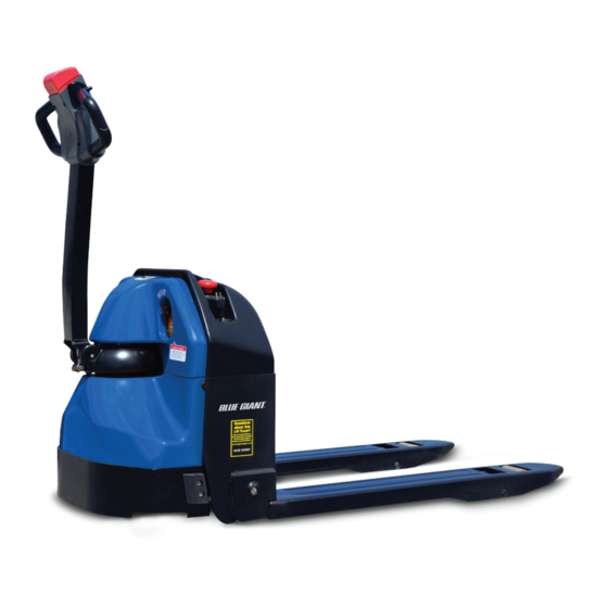
SECTION 1 DESCRIPTION 1-1. INTRODUCTION. forks raised or lowered. The lift truck must be pro- tected from the elements. This publication describes the 24 volt D40 lift truck dis- tributed by Big Lift LLC. Included are operating instruc- The model number will be found on the name plate tions, planned maintenance instructions, lubrication (Figure 1-1) along with the serial number, lifting capac-... -
Page 8: Safety Features
1-3. SAFETY FEATURES. • Readily accessible horn button. The D40 is designed and engineered to provide maxi- • Handle to provide a firm hand hold for operator. mum safety for operator and payload. Some of the • Flow control valve regulates maximum lowering safety features incorporated into the design are: speed within prescribed limits. -
Page 9: Operation2-1
SECTION 2 OPERATION 2-1. GENERAL. • Always look in direction of travel. Keep a clear view, and when load interferes with visibility, travel with This section gives detailed operating instructions for load or lifting mechanism trailing. the D40 lift truck. The instructions are divided into the various phases of operations, such as operating lift, •... -
Page 10: Name Plate
Table 2-1 Operator Checks ITEM PROCEDURE ITEM PROCEDURE Wheels Check drive wheel for cracks or Transmission Check for signs of fluid leakage. damage. Move truck to check and hydraulic load for freedom of rotation. systems. Hydraulic Check operation of lift and lower Forks Check for cracks and damage. -
Page 11: Figure 2-1Sample Of Operator Check List
R6479 Figure 2-1 Sample of Operator Check List... -
Page 12: General Control Operation
2-4. GENERAL CONTROL OPERATION. The speed control (See Figure 2-2) located on each side of the control head provides fingertip control for driving the truck. Rotate the control in the direction you want to travel. The farther you rotate the control from the neutral position, the faster the truck will travel. -
Page 13: Steering Arm Gas Spring
2-9. BACKREST. An adjustable load backrest (Figure 12-9) is incorpo- rated. Backrest (3) is adjustable to 46” forks for stan- dard pallets and 36” for beverage pallets. Handle (4) is used to secure the backrest in the raised position for full use of 46”... - Page 14 NOTES...
-
Page 15: Planned Maintenance3-1
SECTION 3 PLANNED MAINTENANCE 3-1. GENERAL. CAUTION: Gases produced by a battery can be explosive. Do not smoke, use an open Planned maintenance consists of periodic visual and flame, create an arc or sparks in the operational checks, parts inspection, lubrication, and vicinity of the battery. -
Page 16: Safety Rules
Although a leakage voltage reading of zero volts may Charge the battery only in areas designated for not be possible, a cleaner battery will have more that use. usable charge for truck operation and not affect opera- Battery terminals should be checked and cleaned tion of electronic devices on the unit. -
Page 17: Charging Batteries
3-4. CHARGING BATTERIES Charging requirements will vary depending on depth of discharge and temperature. Follow safety rules when placing a battery on charge. Proceed as follows: Park truck at charging station with forks lowered and turn the key switch off. Check the condition of the AC cord and battery cables. -
Page 18: Batteries Replacement
3-5. BATTERIES REPLACEMENT Remove the hose and harness (3, Figure 3- 3) and battery cable (2). Remove four screws Access to the batteries requires moving the controller (3) and take out the controller board (4). board. Proceed as follows: Remove two screws (1, Figure 3-2) and remove cover (2). -
Page 19: Lubrication
3-6. LUBRICATION. Table 3-2 Recommended Lubricants (See Table 3-3 for Application) Refer to Table 3-2 for the recommended types of No. 1 Transmission oil—EP SAE 80W-90 grease and oil. Table 3-3 in conjunction with Figure 3-4 Transmission oil—EP SAE 10W-30 (Note) identifies the items requiring lubrication. -
Page 20: Lubrication Diagram
D40-27 Figure 3-4 Lubrication Diagram Table 3-3 Lubrication Chart FIG 3-2 LOCATION METHOD OF TYPE APPLICATION INDEX APPLICATION (Table 3-3) LUBRICANT Transmission No. 1 Fill to level plug opening Capacity 2 pints Hydraulic Reservoir No. 3 With lift carriage fully lowered, fill Capacity-1 quarts reservoir with hydraulic oil to 1 inch below opening... -
Page 21: General
SECTION 4 TROUBLESHOOTING 4-1. GENERAL ate: Truck Does Not Operate Forward or Reverse: Trouble With Braking: Trouble With Lifting Or Lower- Table 4-1 as a guide to determine possible ing, and Miscellaneous malfunctions. causes of trouble. The table is divided into five main categories: Truck and Hydraulic System Will Not Oper- Table 4-1 Troubleshooting Chart MALFUNCTION... - Page 22 Table 4-1 Troubleshooting Chart - Continued MALFUNCTION PROBABLE CAUSE CORRECTIVE ACTION TROUBLE WITH BRAKING - Continued Brake drags. Defective electric brake (2, Figure Replace. 12-5). Brake grabs. Defective electric brake (2, Figure Replace. 12-5). Abnormal noise and chatter when Defective electric brake (2, Figure Replace.
- Page 23 Table 4-1 Troubleshooting Chart - Continued MALFUNCTION PROBABLE CAUSE CORRECTIVE ACTION TROUBLE WITH LIFTING OR LOWERING - Continued Forks lift, but will not go down. Defect in hydraulic system Check lowering control switch in control head and lowering sole- noid on valve assembly (17, Figure 12-15).
-
Page 24: Controller Troubleshooting
4-2. CONTROLLER TROUBLESHOOTING • The number of times that each alarm occurs consec- utively 4-2.1. Zapi Handset • The Hour Meter reading (value) when the latest A Zapi Handset is available that is designed specifi- event of every alarm occurred cally for use with the Zapi controller. -
Page 25: Settings And Adjustments
4-2.4. Settings and Adjustments 4-2.4.1. Set Options To set options proceed as follows and refer to Table 4- Connect the Zapi Handset, refer to paragraph 4-2.1. Press the ROLL up button (1, Figure 4-2) and the SET up button (5) at the same time to enter the CONFIG MENU. - Page 26 Table 4-2 Set Options - Continued Parameter Factory Setting Description SET INPUT #2 PRESENT It can be can be set as: • PRESENT: CNA#14 (Table 4-5) is managed as a cutback speed input (SR#2). • OPTION #1: CNA#14 (Table 4-5) is managed as an inching back- ward.
- Page 27 Table 4-2 Set Options - Continued Parameter Factory Setting Description AUX OUTPUT #1 BRAKE This option handles output CNA#3 (Table 4-5). It can be used as: • BRAKE: CNA#3 (Table 4-5) drives an electromechanical Brake. • HYDROCOMNT: CNA#3 (Table 4-5) drives the contractor for a hydraulic steering function when the direction input or brake pedal input are active or a movement of the truck is detected.
- Page 28 Parameter Factory Setting Description AUX VOLTAGE #1 100% This option specifies the percentage of the keyswitch controlled voltage to be applied to the loads on CNA#1 (Table 4-5) (main contactor coil) and CNA#3 (Table 4-5) (electromechanical brake). The voltage modulation is set with a PWM at 1 kHz frequency. After an initial delay of about 1 sec in which the entire keyswitch controlled voltage is applied to the loads, the PWM reduces the voltage at the loads down to the specified percentage.
-
Page 29: Figure 4-3Zapi Handset
4-2.4.2. Adjustments To change an adjustment proceed as follows and refer Table 4-3: Connect the Zapi Handset, refer to paragraph 4-2.1. Press the ROLL up button (1, Figure 4-3) and the SET up button (5) at the same time to enter the CONFIG MENU. -
Page 30: Figure 4-4Throttle Regulation
Parameter Factory Setting Description THROTTLE X POINT This parameter together with the THROTTLE Y POINT, changes the characteristic of the accelerator input curve: when the acceler- ator is de-pressed to X point percent, the corresponding truck speed is Y point percent of the Maximum truck speed. The rela- tionship between the accelerator position and the truck speed is linear between the THROTTLE 0 ZONE and the X point and also between the X point and the maximum accelerator position but... -
Page 31: Figure 4-5Zapi Handset
4-2.4.3. Parameter Change To change a parameter proceed as follows and refer to Table 4-4: Connect the Zapi Handset, refer to paragraph 4-2.1. Press the ROLL down button (1, Figure 4-5) and the ENTER button (3) at the same time to enter the MAIN MENU. - Page 32 Table 4-4 Parameter Adjustments - Continued Parameter Factory Setting Description CUTBACK SPEED 100% Typically from 10% to 100%. It determines the percentage of the max speed applied when the cutback switch 1 (SR#1 on CNA#15 (Table 4-5) is active. When set to 100% the speed reduction is ineffective.
-
Page 33: Zapi Controller
R6628 Figure 4-6 Zapi Controller Connections Table 4-5 Zapi Controller Connector Pins CNA Connector ABBREVATION DESCRIPTION CNA#1 Negative of main contactor coil. CNA#2 Positive of main contactor coil. CNA#3 Output for driving the electromechanical brake coil; drives the load to -Batt. Maximum current: 3 A. CNA#4 Negative of pump contactor soil. - Page 34 CNA Connector - Continued ABBREVATION DESCRIPTION CNA#12 -BATT -Batt. CNA#13 MOT TH Motor thermal sensor input. The internal pull-up is a fixed 2mA (Max 5V) source current. CNA#14 Speed reduction 2 input. Active low (switch opened). CNA#15 Speed reduction 1 input. Active low (switch opened). CNA#16 +12V This output provides a +12V signal for the MDI PRC, it present;...
- Page 35 CNC Connector CONNECTOR ABBREVATION DESCRIPTION CNC#1 PCLRXD Positive serial reception. CNC#2 NCLRXD Negative serial reception. CNC#3 PCLTXD Positive serial transmission. CNC#4 NCLTXD Negative serial transmission. CNC#5 Negative console power supply. CNC#6 +12V Positive console power supply. CNC#7 FLASH Must be connected to C8 for the Flash memory programming (if used).
- Page 36 NOTES 4-16 BG-D40-0131...
-
Page 37: Steering Arm, Control Head And Compartment
SECTION 5 STEERING ARM, CONTROL HEAD AND COMPARTMENT 5-1. CONTROL HEAD Remove the cap assembly (24, Figure 5-2) as described in paragraph 5-1.3. 5-1.1. Control Head Removal Disconnect harness (15, Figure 5-1) from potenti- Turn off key switch (21, Figure 12-20) and emer- ometer (21, Figure... -
Page 38: Figure 5-2Control Head
Disconnect harness (15, Figure 5-1) from emer- WARNING: When removing the control head in the gency reverse switch (26, Figure 5-2). following steps, be sure to hold it in place until the control harness is disconnected. Remove two screws (5), two washers (7) and two flat washers (6). -
Page 39: Control Head Installation
5-1.2. Control Head Installation Remove screw (16), screw (22), two lock washers (6) and two flat washers (7) and remove potenti- Secure control head and handle (19, Figure 5-2) ometer (21) and switch assembly (26) from with two screws (11), two washers (12) and two bracket (20). -
Page 40: Figure 5-3Emergency Reverse Switch As
D40-4 Figure 5-3 Emergency Reverse Switch Assembly 5-1.7. Horn Switch Replacement. Solder harness (23) to new switch. Position new switch in bracket of assembly (10) Remove the cap assembly as described in para- and secure with the two pins. graph 5-1.3. -
Page 41: Figure 5-4Cap Assembly
D40-3 Figure 5-4 Cap Assembly 5-1.8. Lift and Lower Switch Replacement. Unsolder harness (23, Figure 5-2) from defective switch. Remove the cap assembly as described in para- Solder the harness to new switch. graph 5-1.3. Position switches and four springs (4, Figure 5-4) Remove switch assembly (13 or 14,... -
Page 42: Compartment Covers
5-2. COMPARTMENT COVERS Remove two screws (7), two screws (8) and mid- dle cover (9). 5-2.1. Removal. Pull lower cover (3) up and out. Turn off key switch (21, Figure 12-20) and emer- 5-2.2. Installation. gency disconnect (2, Figure 12-19). Pull charger cable up and remove cap (6, Figure Position lower cover (3,... -
Page 43: Steering Arm
Feed the cable through cover (1, Figure 5-5) and Position the new gas return spring (3) inside the position cover (1) on the frame. Secure with two steering arm being sure it fully engages its seat. screws (4) and two washers (5). Position the opposite end of gas return spring (3) Install cap (4) on cable (3) and position the cap on on bracket (17) and install screw (4). - Page 44 BG-D40-0131...
-
Page 45: Brake Servicing6-1
SECTION 6 BRAKE SERVICING 6-1. BRAKES. The threaded air gap adjusting nuts are then screwed clockwise until they bottom. The brake system consists of a drive motor mounted brake. This brake is spring applied and electrically Finally tighten the three mounting screws to released. -
Page 46: Stopping Distance Adjustment
6-1.2. Stopping Distance Adjustment. Install the compartment covers as described in paragraph 5-2. The stopping distance of the truck should require mini- mal adjustment. However, this distance should be 6-1.3. Brake Assembly Replacement checked with each planned maintenance. Block load wheels. Using an unloaded truck, run truck to its top speed on Remove the compartment covers as described in an even dry concrete surface. -
Page 47: Transmission, Drive Wheel, Load Wheel7-1
SECTION 7 TRANSMISSION, DRIVE WHEEL, LOAD WHEEL BG-D40-0131... -
Page 48: Load Wheel
7-1. Load Wheel. 7-1.2. Repair Remove bearings (1, Figure 7-1) from wheels (2). 7-1.1. Removal Inspect bearings (1) and replace if necessary. Raise forks. Reassemble bearings (1) in wheels (2). Turn off key switch (21, Figure 12-20) and emer- gency disconnect (2, Figure 12-19). -
Page 49: Drive Wheel
7-2. Drive Wheel. Remove the compartment covers as described in paragraph 5-2. Turn off key switch (21, Figure 12-20) and emer- Remove the brake (2, Figure 7-2) as described in gency disconnect (2, Figure 12-19). paragraph 6-1.3. Remove the compartment covers as described in Remove the steering arm as described in para- paragraph 5-2. -
Page 50: Figure 7-2Transmission Motor, Brake
D40-5 Figure 7-2 Transmission Motor, Brake Mounting BG-D40-0131... -
Page 51: Elevation System Servicing8-1
SECTION 8 ELEVATION SYSTEM SERVICING 8-1. GENERAL Turn off key switch (21, Figure 12-20) and emer- gency disconnect (2, Figure 12-19). The elevation system includes the lift linkage, front Remove screw (24, Figure 8-1) and shaft (15) frame and back frame. from each side of frame (14). -
Page 52: Repair
8-2.2. Repair Install reassemble by reversing the steps above. Remove pins (11, Figure 8-2), shafts (12) and 8-2.3. Installation load wheel (13) from wheel brackets (8). Position link assembly under frame (4). Remove pins (11) and shafts (10). Free brackets Position wheel brackets (8, Figure 8-2) in frame... -
Page 53: Hydraulic System Servicing9-1
SECTION 9 HYDRAULIC SYSTEM SERVICING 9-1. LINES AND FITTINGS NOTE: Leaking hydraulic fittings may be remedied by simply tightening fittings. If this does not rem- WARNING: When forks are raised, pressure exists in edy the leak, the fittings or line must be the hydraulic system lines and fittings. -
Page 54: Hydraulic And Electrical Assembly
CAUTION: Hydraulic oil can damage parts. Wipe off 9-2.2. Installation any oil immediately. Provide a container Position board (4, Figure 12-17) on frame and under the line or fitting before discon- secure with four screws (1, Figure 12-17), four necting. lock washers (2) and four flat washers (3). -
Page 55: Figure 9-2Pump & Motor Assy
D40-15 Figure 9-2 Pump & Motor Assy BG-D40-0131... -
Page 56: Installation
9-3.3. Installation 9-3.4.2.Repair Position pump and motor (4, Figure 9-1) on board Secure the lift cylinder in a vise, clamping lightly and secure with two screws (5), lock washers (6) at the base of the cylinder. and flat washers (7). Unscrew gland nut (4, Figure 9-3) from body (5). - Page 57 BG-D40-0131...
- Page 58 NOTES BG-D40-0131...
-
Page 59: Electrical Components10-1
SECTION 10 ELECTRICAL COMPONENTS 10-1.ELECTRICAL CONTROL PANEL Tag and disconnect harness (1, Figure 12-21) from controller (18, Figure 10-1). 10-1.1.Maintenance Remove four screws (16), lock washers (17) and remove controller (18). NOTE: Erratic operation of the truck may be caused by defective controller components. -
Page 60: 10-1.7.Emergency Disconnect Removal
10-1.7.Emergency Disconnect Removal. Tag and disconnect wires from contactor (19, Fig- 10-1). Turn off key switch (21, Figure 12-20) and emer- Remove two screws (8), lock washers (9), flat gency disconnect (2, Figure 12-19). washers (10) and remove contactor (19). Remove the compartment covers as described in paragraph 5-2. -
Page 61: Figure 10-1Electrical Components
D40-18 Figure 10-1 Electrical Components (Sheet 1) BG-D40-0131 10-3... -
Page 62: 10-1.13.Cooling Fan Removal
10-1.13.Cooling Fan Removal. Turn on key switch (21, Figure 12-20) and emer- gency disconnect (2, Figure 12-19). Turn off key switch (21, Figure 12-20) and emer- gency disconnect (2, Figure 12-19). 10-1.17.Key Switch Removal. Remove the compartment covers as described in Turn off key switch (21, Figure 12-20) and emer-... -
Page 63: Figure 10-2Electrical Components
D40-19 Figure 10-2 Electrical Components (Sheet 2) BG-D40-0131 10-5... -
Page 64: 10-1.21.Lift Limit Switch Removal
10-1.21.Lift Limit Switch Removal. 10-1.22.Lift Limit Switch Installation. Lower forks fully. Position limit switch (17, Figure 10-3) on bracket (15) and secure with two screws (19), lock wash- Turn off key switch (21, Figure 12-20) and emer- ers (20) and nuts (21). gency disconnect (2, Figure 12-19). -
Page 65: Deadman Switch
10-2.PUMP MOTOR. Remove the compartment covers as described in paragraph 5-2. The pump motor is replaceable but not repairable. Disconnect wiring from the deadman switch (16, Refer to paragraph 9-3. Figure 12-1). 10-3.DRIVE MOTOR. Remove the two screws (19), lock washers (20) and bracket (18) from bracket (17). - Page 66 NOTES 10-8 BG-D40-0131...
-
Page 67: Optional Equipment11-1
SECTION 11 OPTIONAL EQUIPMENT BG-D40-0131 11-1... - Page 68 NOTES 11-2 BG-D40-0131...
-
Page 69: Illustrated Parts Breakdown12-1
SECTION 12 ILLUSTRATED PARTS BREAKDOWN Following is an illustrated parts breakdown of assemblies and parts associated with the D40 Lift Truck. BG-D40-0131 12-1... -
Page 70: Figure 12-1Steering Arm
D40-1 Figure 12-1 Steering Arm 12-2 BG-D40-0131... -
Page 71: Steering Arm
Steering Arm Pos. Part Number Description Qty. Notes Reqd. 1120-340000-00-B CONTROL HEAD ASSEMBLY FIGURE 12-2 1120-330000-0A CONTROL ARM ASSEMBLY 1120-320000-00 GAS SPRING 0000-000151-00 SCREW, M8 X 25 1120-300003-00 SHAFT 0000-000011-00 BUSHING, 2015 0000-000386-00 SCREW, M5 X 20 1120-300005-00 BRACKET 0000-000016-00 SCREW, M6 X 8 10 0000-000030-00 SCREW, M10 X 16... -
Page 72: Figure 12-2Control Head
D40-2 Figure 12-2 Control Head 12-4 BG-D40-0131... -
Page 73: Cap Assembly
Control Head Pos. Part Number Description Qty. Notes Reqd. — CAP ASSEMBLY REF See pos. # 24 1120-340005-00 CONTROL KNOB RIGHT SIDE 0000-000038-00 LOCK WASHER, M3 0000-000037-00 SCREW, M3 X 15 0000-000004-00 SCREW, M5 X 12 0000-000206-00 LOCK WASHER, M5 0000-000390-00 FLAT WASHER, M5 0000-000088-00... - Page 74 D40-2 Figure 12-2 Control Head - Continued 12-6 BG-D40-0131...
-
Page 75: Control Head
Control Head - Continued Pos. Part Number Description Qty. Notes Reqd. 22 0000-000010-00 SCREW, M5 X 6 CONTROL HEAD M. SWITCH AND 23 1120-343000-00-B HARNESS ASSEMBLY 24 1120-342000-00-B CAP ASSEMBLY BG-D40-0131 12-7... -
Page 76: Figure 12-3Cap Assembly
D40-3 Figure 12-3 Cap Assembly 12-8 BG-D40-0131... - Page 77 Cap Assembly Pos. Part Number Description Qty. Notes Reqd. 1120-342001-00 COVER 1120-342203-00 BUTTON FOR LIFTING (R) 1120-342202-00 BUTTON FOR LOWERING (R) 1120-342102-00 SPRING 1120-342201-00 BUTTON BRACKET (R) 1120-342105-00 1120-342104-00 BUTTON FOR LIFTING (L) 1120-342103-00 BUTTON FOR LOWERING (L) 1120-342101-00 BUTTON BRACKET (L) 10 1120-342002-00 HORN BUTTON —...
-
Page 78: Figure 12-4 Emergency Reverse Switch Assembly
D40-4 Figure 12-4 Emergency Reverse Switch Assembly 12-10 BG-D40-0131... -
Page 79: Emergency Reverse Switch Assembly
Emergency Reverse Switch Assembly Pos. Part Number Description Qty. Notes Reqd. 1120-343002-00 EMERGENCY REVERSE BUTTON 1120-343003-00 SPRING 1120-342005-00 1120-343001-0A BRACKET 1120-343004-00 REVERSING SWITCH WIRE HAR- 1220-520005-0C Incl. switch NESS 1220-560002-00 REVERSING SWITCH BG-D40-0131 12-11... -
Page 80: Figure 12-5Transmission Motor, Brake Mounting
D40-5 Figure 12-5 Transmission Motor, Brake Mounting 12-12 BG-D40-0131... -
Page 81: Brake Assembly
Transmission Motor, Brake Mounting Pos. Part Number Description Qty. Notes Reqd. 0000-000027-00 SCREW, M6 X 55 1120-210000-00 BRAKE ASSEMBLY 1120-220000-00 MOTOR ASSEMBLY FIGURE 12-18 0000-000154-00 SCREW, M8 X 35 0000-000159-00 LOCK WASHER, M8 0000-000176-00 FLAT WASHER, M8 0000-000155-00 SCREW, M10 X 40 0000-000063-00 LOCK WASHER, M10 0000-000007-00... -
Page 82: Figure 12-6Transmission Transmission Used Up To Serial # E2219364
D40-6 Figure 12-6 Transmission Transmission Used up to Serial # E2219364 12-14 BG-D40-0131... - Page 83 ransmission Used up to Serial # E2219364 Pos. Part Number Description Qty. Notes Reqd. 1120-240001-30 GEAR CASE 1120-240002-30 PLUG 0000-000214-00 O-RING 135 X 3.1 1120-240003-30 COVER 0000-000056-00 LOCK WASHER, M6 0000-000259-00 BOLT, M6 X 16 1120-240004-30 WASHER — As Required 0000-000961-00 BEARING 1120-240005-30...
- Page 84 D40-6 Figure 12-6 Transmission Used up to Serial # E2219364 12-16 BG-D40-0131...
- Page 85 Transmission Used up to Serial # E2219364 Pos. Part Number Description Qty. Notes Reqd. 26 0000-000025-00 LOCK WASHER, M12 27 0000-000157-00 NUT, M12 X 1.25 28 1120-240015-30 WASHER — As Required 29 1120-240016-30 GEAR 30 1120-240018-30 WASHER BG-D40-0131 12-17...
- Page 86 D40-6 Figure 12-7 Transmission Used from Serial # E2219365 12-18 BG-D40-0131...
- Page 87 Transmission Used from Serial # E2219365 Pos. Part Number Description Qty. Notes Reqd. 1120-240001-30 GEAR CASE 1120-240002-30 PLUG 0000-000214-00 O-RING 135 x 3.1 1120-240003-30 COVER 0000-000056-00 LOCK WASHER M6 0000-000259-00 BOLT M6 x 16 1120-240004-30 WASHER 0000-000961-00 BEARING 1120-240005-30 PLUG 1120-240006-30 SPIRAL BEVEL GEAR 1120-240007-30...
-
Page 88: Figure 12-7Transmission Used From Serial # E2219365
D40-6 Figure 12-7 Transmission Used from Serial # E2219365 12-20 BG-D40-0131... - Page 89 Transmission Used from Serial # E2219365 Pos. Part Number Description Qty. Notes Reqd. 26 0000-000025-00 LOCK WASHER, M12 27 0000-000157-00 NUT, M12 X 1.25 28 1120-240015-30 WASHER 29 1120-240016-30 GEAR 30 1120-240018-30 WASHER BG-D40-0131 12-21...
-
Page 90: Figure 12-8Compartment Covers
D40-7 Figure 12-8 Compartment Covers 12-22 BG-D40-0131... -
Page 91: Compartment Cover
Compartment Covers Pos. Part Number Description Qty. Notes Reqd. 1118-100001-00-01 COVER Black 1a 1118-100001-00-02 COVER Light Blue 1b 1118-100001-00-06 COVER Dark Blue 1118-100001-00-05 COVER Green 1118-100002-00 UPPER COVER Big Joe Yellow 2a 1118-100002-00-02 UPPER COVER Light Blue 2b 1118-100002-00-05 UPPER COVER Dark Blue 1118-100002-00-04 UPPER COVER... -
Page 92: Figure 12-9Load Backrest
D40-22 Figure 12-9 Load Backrest 12-24 BG-D40-0131... -
Page 93: Load Backrest
Load Backrest Pos. Part Number Description Qty. Notes Reqd. 1118-151000-00 LOAD BACKREST Height 48” (1220mm) 1a 1118-152000-00 LOAD BACKREST Height 60” (1524mm) 0000-000270-00 BOLT 0000-000060-00 LOCKWASHER 10000-000373-00 FLATWASHER BG-D40-0131 12-25... -
Page 94: Figure 12-10Frame
D40-11 Figure 12-10 Frame 12-26 BG-D40-0131... -
Page 95: Frame
Frame Pos. Part Number Description Qty. Notes Reqd. 1 0000-000396-00 SCREW, M6 X 20 2 1118-130005-00 SHAFT 3 0000-000650-00 SNAP RING, M25 4 1118-110000-40 FORK FRAME Fork width 27” (685mm) 4a 1118-110000-20 FORK FRAME Fork width 22” (540mm) 5 1118-130003-00 LINK 6 1115-130004-0A SHAFT... -
Page 96: Figure 12-11Lift Link Assembly
D40-12 Figure 12-11 Lift Link Assembly 12-28 BG-D40-0131... -
Page 97: Load Wheel
Lift Link Assembly Pos. Part Number Description Qty. Notes Reqd. 1 1219-141000-30 DOWN LINK Fork width 27” (685mm) 1a 1219-141000-10 DOWN LINK Fork width 22” (540mm) 2 0000-001034-00 BUSHING 3 1219-140001-00 SHAFT 4 0000-000101-00 NUT, M22 X 1.5 5 1219-142200-00 CONNECTOR 6 1118-132000-30 LONG LINK... -
Page 98: Figure 12-12Load Wheel
D40-13 Figure 12-12 Load Wheel 12-30 BG-D40-0131... - Page 99 Load Wheel Pos. Part Number Description Qty. Notes Reqd. — 1115-133000-40 LOAD WHEEL ASSEMBLY Including bearings 0000-000020-00 BEARING 1115-133002-40 LOAD WHEEL BG-D40-0131 12-31...
-
Page 100: Figure 12-13Caster
D40-23 Figure 12-13 Caster 12-32 BG-D40-0131... -
Page 101: Caster
Caster Pos. Part Number Description Qty. Notes Reqd. — 1118-140000-00 CASTER ASSEMBLY 0000-000985-00 SCREW, M10 X 20 1118-140003-00 PLATE 1118-140001-00 CASTER SUPPORT 0000-000986-00 BEARING 1118-140002-00 CASTER SUPPORT 0000-000168-00 BOLT, M10 X 90 1120-140003-00 PU BLOCK 1120-142000-00 WHEEL BRACKET 0000-000495-00 BOLT, M12 X 85 10 1120-143001-00 SHAFT 0000-000020-00... -
Page 102: Figure 12-14Hydraulic System
D40-14 Figure 12-14 Hydraulic System 12-34 BG-D40-0131... -
Page 103: Hydraulic System
Hydraulic System Pos. Part Number Description Qty. Notes Reqd. 2706-141400-00 CONNECTOR, M14 X 1.5 0000-000044-00 WASHER, M14 1118-430000-00 HOSE ASSY 1118-420000-00 PUMP & MOTOR ASSY FIGURE 12-15 0000-000321-00 SCREW, M8 X 20 0000-000159-00 LOCK WASHER, M8 0000-000176-00 FLAT WASHER, M8 1118-410000-00 CYLINDER FIGURE 12-16... -
Page 104: Figure 12-15Pump & Motor Assy
D40-15 Figure 12-15 Pump & Motor Assy 12-36 BG-D40-0131... - Page 105 Pump & Motor Assy Pos. Part Number Description Qty. Notes Reqd. — 1118-420000-00 PUMP & MOTOR ASSY 1118-420001-00 CLAMP 1118-420002-00 WIRE HARNESS 1118-420003-00 DC MOTOR, 0.8KW/24V 1118-420004-00 RELAY, 24V/150A 1118-420005-00 SCREW, M8 X 8 1118-420006-00 BALL, 6G20b 1118-420007-00 VALVE PLATE 1118-420008-00 SAFETY VALVE 1118-420009-00...
-
Page 106: Figure 12-16Lift Cylinder
D40-16 Figure 12-16 Lift Cylinder 12-38 BG-D40-0131... -
Page 107: Lift Cylinder
Lift Cylinder Pos. Part Number Description Qty. Notes Reqd. — 1118-410000-00 LIFT CYLINDER — 1118-QSY-0A SEAL KIT Includes Items 2, 3, 1118-410001-00 PISTON ROD 0000-000672-00 WIPER RING, M40 X 50 X 5-6.5 0000-000673-00 O-RING, M45 X 3.1 1115-410002-0B GLAND NUT 1118-411000-00 CYLINDER BODY 1115-410003-0B... -
Page 108: Figure 12-17Electrical System
D40-17 Figure 12-17 Electrical System 12-40 BG-D40-0131... -
Page 109: Electrical System
Electrical System Pos. Part Number Description Qty. Notes Reqd. 0000-000030-00 SCREW, M10 X 16 0000-000063-00 LOCK WASHER, M10 0000-000007-00 FLAT WASHER, M10 1118-511000-00 MOUNTING PLATE 0000-000368-00 SCREW, M8 X 12 2214-150002-00 WASHER 0000-000108-00 NUT, M6 1118-540000-00 BOARD 0000-000117-00 SCREW, M5 X 10 10 0000-000206-00 LOCK WASHER, M5 0000-000390-00... -
Page 110: Figure 12-18Motor Assembly
D40-8 Figure 12-18 Motor Assembly 12-42 BG-D40-0131... -
Page 111: Motor Assembly
Motor Assembly Pos. Part Number Description Qty. Notes Reqd. 0000-000293-00 RETAINING RING, M20 0000-000226-00 1120-220001-00 TERMINAL BLOCK 0000-000206-00 LOCK WASHER, M5 0000-000117-00 SCREW, M5 X 10 0000-000166-00 NUT, M6 0000-000056-00 LOCK WASHER, M6 1120-220002-00 BEARING 0000-000204-00 10 0000-000409-00 O-RING, M63 X 3.55 0000-000436-00 NUT, M12 X 1.5 12 0000-000323-00... -
Page 112: Figure 12-19Electrical Components
D40-18 Figure 12-19 Electrical Components (Sheet 1) 12-44 BG-D40-0131... - Page 113 Electrical Components (Sheet 1) Pos. Part Number Description Qty. Notes Reqd. 0000-000119-00 SCREW, M5 X 12 1115-510008-00 EMERGENCY STOP SWITCH 1118-510002-00 MOUNTING PLATE 0000-000700-00 SCREW, M8 X 16 0000-000159-00 LOCK WASHER, M8 0000-000176-00 FLAT WASHER, M8 1118-510005-00 UPPER MOUNTING PLATE 0000-000077-00 SCREW, M6 X 12 0000-000056-00...
- Page 114 D40-19 Figure 12-20 Electrical Components (Sheet 2) 12-46 BG-D40-0131...
- Page 115 Electrical Components (Sheet 2) Part Number Description Qty. Notes Reqd. Used when Break 1118-560001-00 TIMING RELAY Release Option on truck Used when Break 1118-560002-00 TIMING RELAY SET Release Option on truck Used when Break 1118-510001-00 RELAY BRACKET Release Option on truck Used when Break 0000-000009-00...
-
Page 116: Figure 12-20Electrical Components (Sheet 2)
D40-19 Figure 12-20 Electrical Components (Sheet 2) - Continued 12-48 BG-D40-0131... -
Page 117: Electrical Components (Sheet 2)
Electrical Components (Sheet 2) - Continued Part Number Description Qty. Notes Reqd. 21 1115-500016-00 2-WAY SWITCH KEY 22 1115-520013-00 LED WIRE HARNESS 23 1115-510009-00 LAMP HOLDER Used when Break 24 CK11-520012-00 BRAKE RELEASE BUTTON Release Option on truck 25 1115-520005-0A WIRE HARNESS FOR BDI Not used when 26 1280-100005-00... -
Page 118: Figure 12-21Wiring Harness
D40-20 Figure 12-21 Wiring Harness 12-50 BG-D40-0131... -
Page 119: Wiring Harness
Wiring Harness Pos. Part Number Description Qty. Notes Reqd. 1118-520001-00 MASTER WIRE HARNESS 1120-500010-00 FUSE 10A 1118-520002-00 SWITCHING WIRE HARNESS 1118-520004-00 WIRE HARNESS OF PUMP BG-D40-0131 12-51... -
Page 120: Figure 12-22Wiring Cables
D40-21 Figure 12-22 Wiring Cables 12-52 BG-D40-0131... -
Page 121: Wiring Cables
Wiring Cables Pos. Part Number Description Qty. Notes Reqd. 1118-531003-00 CABLE, BATTERY CONNECTOR 1118-531002-00 CABLE, BATTERY - 1118-531001-00 CABLE, BATTERY + 1118-531004-00 F CABLE + 1118-531006-00 M CABLE + 1118-531008-00 B CABLE+ 1118-531007-00 PUMP POWER CABLE + 1118-531005-00 PUMP POWER CABLE - 1118-532001-00 DRIVING MOTOR CABLE U 10 1118-532002-00... - Page 122 NOTES 12-54 BG-D40-0131...
- Page 124 Corporate 85 Heart Lake Road South USA 6350 Burnt Poplar Road Brampton, ON, Canada L6W 3K2 Greensboro, NC 27409 t 905.457.3900 f 905.457.2313 www.BlueGiant.com If calling within North America: t 1.800.668.7078 f 1.888.378.5781 © Copyright Blue Giant Equipment Corporation 2014...
Need help?
Do you have a question about the EPJ-40 and is the answer not in the manual?
Questions and answers