
Related Manuals for Mircom FX-2003-6DS


Summary of Contents for Mircom FX-2003-6DS
- Page 1 FX-2000 Intelligent Analog Fire Alarm Control Panel LT-657 Rev 15 Installation and Operation Manual December 2016 For the latest compatability information visit www.mircom.com/deviceguide...
-
Page 2: Table Of Contents
Document Conventions System Components Mechanical and Chassis Installation Module Mounting Locations Display and Adder Modules Mounting Locations FX-2003-6DS/FX-2003-12DS/FX-2003-6DS-16LED Compact Main Chassis ....FX-2017(S)-12DS Mid-size Main Chassis ..............FX-2009(S)-12DS Large Main Chassis ................ECX-0012 Expander Chassis for FX-2009-12DS ............Module Settings Main Fire Alarm Modules (MD-764 Part of Main Chassis) .......... - Page 3 10.0 Indicators and Controls 11.0 Operation 11.1 Single Stage Operation ....................11.2 Two Stage Operation ..................... 11.3 Pre-Signal Operation ...................... 11.4 UUKL feature ......................... 11.5 Output Circuit Delay Operation ..................11.6 Circuit Types ........................12.0 Appendix A: Specifications 13.0 Appendix B: Compatible Devices 13.1 FX-2000 Series Compatible Addressable Loop Devices (UL) ........
-
Page 4: Introduction
Introduction About the FX-2000 Mircom's cost-effective FX-2000 Intelligent Analog Fire Alarm Control Panel (FACP) is a flexible and easy-to-use analog system. The FX-2000 base panel consists of: one intelligent analog loop controller capable of supporting 99 analog sensors and 99 addressable modules that can be wired in Class A (Style 6 or 7) or Class B (Style 4). - Page 5 Introduction Common controls and indicators for System Reset, Lamp Test, Fire Drill, Signal Silence, • General Alarm, General Alarm Cancel, AC On, Pre-Alarm, and Ground Fault. • Two Spare configurable Keys and LED Indicators. • 16 configurable LEDs (bi-coloured) with slide-in labels, available with the DSPL-420- •...
-
Page 6: Document Conventions
Document Conventions Document Conventions Circuits and Zones The term circuits refers to an actual electrical interface, initiating (detection), NAC (signal), or relay. The term zone is a logical concept for a fire alarm protected area, and will consist of at least one circuit. -
Page 7: System Components
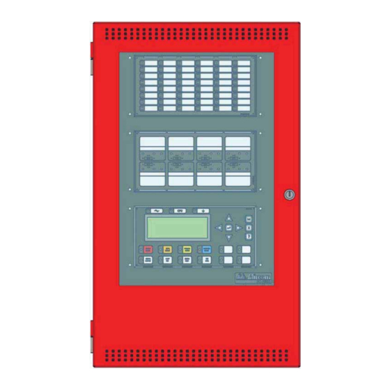
System Components System Components FX-2000 Chassis Types FX-2003-6DS (pictured on the left) FX-2017-12ADS FX-2003-6DS-16LED (pictured on the right) FX-2017S-12ADS FX-2003-12DS (pictured on the left) FX-2009-12DS FX-2003-12XTDS FX-2009S-12DS ECX-0012 Expander Chassis... - Page 8 # of # of # of Max # of Mounts into Addressable NACs Adder Conventional Display loops Modules Adder Adders Modules UB-1024DS FX-2003-6DS FX-2003-6DS- UB-1024DS 16LED UB-1024DS FX-2003-12DS BBX-1024XT FX-2003-12XTDS BBX1024XTR BB-5008 or FX-2009-12DS BB-5014 BB-5008 or FX-2009S-12DS BB-5014 BBX-1072ADS...
- Page 9 Detection, Signal and Relay. RM-1008A Optional main display with 16 configurable bi-coloured LEDs. DSPL-420-16TZDS This display is included in the FX-2003-6DS-16LED chassis package. Auxiliary Modules The following table describes the auxiliary modules used with the FX-2000. Table 3 FX-2000 Auxiliary Modules Model Description...
- Page 10 System Components Enclosures The following table describes the enclosures used with the FX-2000. Table 4 FX-2000 Enclosures Model Description Backbox 36”H x 30”W x 7”D BB-5008 Backbox 60”H x 30”W x 7”D BB-5014...
- Page 11 Table 4 FX-2000 Enclosures Model Description UB-1024DS Universal Backbox UB-1024DS 26”H x 14.5”w x 4.2”D DOX-1024DS DOX-1024DS white door for universal backbox. DOX-1024DSR DOX-1024DSR red door or universal backbox. Complete system with DSPL-420-16TZDS FX-2003-6DS- display and UB-1024DS backbox and 16LED DOX-1024DSR door.
- Page 12 System Components Table 4 FX-2000 Enclosures Model Description Enclosure 35.5”H x 14.5”w x 5.25”D, white door BBX-1024XT Enclosure 35.5”H x 14.5”w x 5.25”D, red door BBX-1024XTR Enclosure 24.8” x 32.5” x 6.4”, white door BBX-1072ADS Enclosure 24.8” x 32.5” x 6.4”, red door BBX-1072ARDS...
- Page 13 System Components Flush Trim Ring The following table describes the flush trim ring used with the FX-2000. Table 5 FX-2000 Flush Trim Ring Model Description Black flush trim ring for BBX-1024XT and FA-XT-TRB BBX-1024XTR. Remote Annunciators The following table describes the remote annunciators used with the FX-2000. Table 6 FX-2000 Remote Annunciators Description Model...
- Page 14 System Components Table 6 FX-2000 Remote Annunciators Description Model Remote graphic annunciator drivers. The AGD-048 MGD-32, must be installed in the same enclosure as the AGD-048 MGD-032. Remote Shared Display Annunciator RAX-LCD Batteries The following table describes the batteries used with the FX-2000. Table 7 Batteries Model Description...
-
Page 15: Mechanical And Chassis Installation
Mechanical and Chassis Installation Mechanical and Chassis Installation The following chapter describes the Mechanical and Chassis installation for all FX-2000 FACPs. Mechanical Installation Diagrams Mechanical Installation Instructions for the following enclosures: BB-5008 • BB-5014 • UB-1024DS and DOX-1024DS/R • BBX-1024XT •... - Page 16 Mechanical and Chassis Installation Figure 1 BBX-1072ADS and BBX-1072ARDS Flush or Surface Enclosure Installation and Dimensions Note: Leave bottom of box conduit free for batteries.
- Page 17 Mechanical and Chassis Installation 4.1.2 BB-5008 Mechanical Installation Cold rolled steel18GA (0.048”) thick cold rolled steel Material 16GA (0.059”) thick for backbox 14GA (0.075”) thick for door BB-5008 Backbox Backbox Backbox with DOX-5008M Door DOX-5008M Metal Door Figure 2 BB-5008 Enclosure Installation Instructions and Dimensions Leave bottom of box conduit free for batteries.
- Page 18 Mechanical and Chassis Installation 4.1.3 BB-5014 Mechanical Installation Cold rolled steel18GA (0.048”) thick cold rolled steel Material 16GA (0.059”) thick for backbox 14GA (0.075”) thick for door Painted except for hinges Finish BB-5014 Backbox Backbox Backbox with DOX-5014M Door DOX-5014M Metal Door Figure 3 BB-5014 Installation Instructions and Dimensions Leave bottom of box conduit free for batteries.
- Page 19 Mechanical and Chassis Installation 4.1.4 UB-1024DS and DOX-1024DS/R Mechanical Installation The universal enclosure is suitable for flush or surface mounting, and have a built-in trim ring. 26” x 14.5” x 4.25” Dimensions of backbox (minus built in trim ring) 12” Distance between horizontal mounting screws 23.5”...
- Page 20 Mechanical and Chassis Installation 4.1.5 FX-2003-12XTDS Mechanical Installation FX-2003-12XTDS is an expanded version of the FX-2003-12DS. 14.76” wide by 35.8” long by 5.45” Dimensions 16GA (0.059”) thick for backbox 14GA (0.075”) thick for door Painted except for hinges Finish 12.000 Mounting Holes Adhere trim ring to wall surface around backbox.
- Page 21 Mechanical and Chassis Installation 4.1.6 Surface and Flush Mounting Views of the BBX-1024XT/R 5.45” 0.7” Figure 6 BBX-1024XT/R Surface and Flush Side Views 4.1.7 BBX-1024XT Flush Mounted Box with FA-XT-TRB Trim Ring TRIM RING WALL WOOD OR METAL STUD BACKBOX Figure 7 Cross section view of mounted BBX-1024XT/R enclosure...
- Page 22 Mechanical and Chassis Installation Chassis Installation Chassis Installation Instructions for the following: FX-2003-6DS • FX-2003-12DS • FX-2003-12XTDS • FX-2009-12DS • FX-2009S-12DS • FX-2017-12ADS • FX-2017S-12ADS • ECX-0012 • For proper chassis installation do the following 1. Group the incoming wires through the top of the enclosure to prepare it for wiring the modules.
- Page 23 Mechanical and Chassis Installation 4.2.1 Mounting the Chassis into the BBX-1072ADS or BBX-1072ARDS Enclosure Mount chassis FX-2017-12ADS or FX-2017S-12ADS into backbox BBX-1072ADS or BBX- 1072ARDS using the supplied four #6 hex nuts (two at the top and two at the bottom) as shown below.
- Page 24 Mechanical and Chassis Installation 4.2.2 Mounting the Chassis into the BB-5008 or BB-5014 The chassis is mounted using the four #6 hex nuts provided. Two across the top portion and two across the bottom of the chassis. The inner door is mounted using four hex nuts on the left side and secured with two screws on the right side.
- Page 25 Mechanical and Chassis Installation 4.2.3 Mounting the Chassis into the UB-1024DS and DOX-1024DS/R Enclosure The chassis is mounted using the six #8 hex nuts provided. Three across the top and three across the bottom of the chassis. The inner door mounts over the chassis with two #8 hex nuts.
-
Page 26: Module Mounting Locations
Module Mounting Locations Module Mounting Locations The FX-2003-6DS/12DS or FX-2017-12ADS Main Chassis come pre-assembled with a main chassis, display components and boards. Install adder modules of different types as shown in the diagrams on the following pages. PR-300 CITY TIE MODULE... - Page 27 Module Mounting Locations Provision for PR-300 or UDACT-300A Figure 12 Module Mounting Locations View #2...
-
Page 28: Display And Adder Modules Mounting Locations
Display and Adder Modules Mounting Locations Display and Adder Modules Mounting Locations FX-2003-6DS/FX-2003-12DS/FX-2003-6DS-16LED Compact Main Chassis Mounts in the UB-1024DS backbox and supports three circuit adder modules. Exterior View Interior View Slot is reserved for PR-300 or UDACT- 300A. If not... -
Page 29: Fx-2009(S)-12Ds Large Main Chassis
Display and Adder Modules Mounting Locations FX-2009(S)-12DS Large Main Chassis Mounts and occupies four display positions in BB-5008 or BB-5014 Enclosures, and supports two display modules and nine adder modules. Exterior View Interior View Cutout to mount Cutout to mount display module display module FX-2000 Main Board... - Page 30 Display and Adder Modules Mounting Locations Mounting the Boards to the BBX-1024XT Chassis The main board is mounted to the chassis and is shipped out this way. Mounts up to 9 adder modules and one display module such as RAX-1048TZDS Programmable 48 Zone and Trouble LED display module, IPS-2424DS Programmable Input Switches module and FDX-008W Fan Damper module.
- Page 31 6.5.2 Display Modules Each display module occupies one display position and mounts to the display cutouts on the following chassis: FX-2003-6/FX-2003-12 Compact Main Chassis • FX-2003-6DS/FX-2003-6DS-16LED/FX-2003-12DS Compact Main Chassis • FX-2003-12XT/FX-2003-12XTDS Mid-size Main Chassis • FX-2017-12DS Mid-size Main Chassis •...
-
Page 32: Module Settings
Module Settings Module Settings Main Fire Alarm Modules (MD-764 Part of Main Chassis) Remove jumper if a PR-300 or UDACT-300A is installed. Jumpers are factory set and should not be changed. JW2 to JW4 Black RS-485 Connector connects to the Adder Loop ALC-198S, ALC-396S or ALC-H16 if used (Address Loops 3, 4, etc) Connector for PR-300 module or UDACT-300A. -
Page 33: Main Fire Alarm Super Module (Md-757 Part Of "S" Version Main Chassis)
Module Settings Main Fire Alarm Super Module (MD-757 Part of “S” Version Main Chassis) This super main board does not have any addressable loops on it. For an addressable loop, adder boards are required. Remove jumper if a PR-300 or UDACT-300A is installed. Jumpers are factory set and should not be changed. - Page 34 Module Settings 7.2.1 DSPL-420 Main Display Module Cable connects to P14 of main fire alarm module Connection to P1 of any adder display module if used. Figure 16 DSPL-420 Main Display Module The main display module comes with slide-in paper labels including both English Note: and French slide-ins, and laser printer-compatible blanks for zone labelling.
-
Page 35: Rax-1048Tzds Zone Display Module
Module Settings RAX-1048TZDS Zone Display Module Cable connects to P2 of previous display module. Cable connects to P1 of next display module. Figure 18 Zone Display Module (RAX-1048TZDS) IPS-2424DS Programmable Input Switches Module Cable connects to P2 of previous display module. Cable connects to P1 of next display module. -
Page 36: Fan Damper Control Display Module (Fdx-008W/Wki)
Module Settings Fan Damper Control Display Module (FDX-008W/WKI) There are two models of the Fan Damper Control Display modules available. The FDX-008W provides switch control and LED indication of 8 fan damper zones. The FDX-008WKI provides switch control of 7 fan damper zones with the eighth zone activated by keyswitch. LED indication is provided for all 8 fan damper zones on the FDX-008WKI. - Page 37 Module Settings steady amber based on feedback from the monitor module that one or more of the fans is not working. ON LED shows steady for all outputs operating and confirmed. OFF LED shows steady for all outputs NOT operating and confirmed. TRBL LED shows steady for one or more outputs NOT operating and confirmed.
- Page 38 Module Settings Mount the FDX-008W and FDX-008WKI Fan Damper Control Display modules in any position on the front part of the FX-2000 chassis. TERMINALS AT TS1 ARE WIRED TO A KEYSWITCH. NOTE: IF FAN DAMPER MODULE IS MOUNTED TO THE DOOR USE TERMINALS LOCATED AT THE BACK OF THIS BOARD, BEHIND TS1.
-
Page 39: Dm-1008A Hardwire Detection Adder Module
Module Settings DM-1008A Hardwire Detection Adder Module Install jumper for Class A (Style D) operation of initiating circuits 1 and 2. Install jumper for Class A (Style D) operation of initiating circuits 3 and 4. Install jumper for Class A (Style D) operation of initiating circuits 5 and 6. Install jumper for Class A (Style D) operation of initiating circuits 7 and 8. -
Page 40: Sgm-1004A Hardwire Nac Signal Adder Module
Module Settings SGM-1004A Hardwire NAC Signal Adder Module Remove continuity jumper if this is not the last adder module installed. Jumper pins for bell cut or isolators on Zone 1. Jumper pins for bell cut or isolators on Zone 2. Jumper pins for bell cut or isolators on Zone 3. - Page 41 Module Settings 7.7.2 SGM-1004A Operation There are three modes of operation for this module. The basic mode of operation does not involve any bell cut relay or isolators connected to the signal zones. For this case, leave jumpers JW2, JW3, JW4 and JW5 as they come on pins 2 and 3, and do not make any connection to terminal block J11.
-
Page 42: Rm-1008A Hardwire Relay Adder Module
Module Settings RM-1008A Hardwire Relay Adder Module Data cable to P6 or P5 of main fire alarm module, or to P12 or P13 of Hardwire loop controller module, or to previous adder module. Data connector for next adder module. Power connector to P8 of main fire alarm module, or to P2 of Hardwire loop controller or to previous adder module. -
Page 43: Polarity Reversal And City Tie Module (Model Pr-300)
Module Settings Polarity Reversal and City Tie Module (Model PR-300) Mounting hole for #6-32 screws Mounting hole for #6-32 screws Figure 26 Polarity reversal and city tie module The following hardware configuration must be performed before installing the PR-300. Cable connects to P5 on the FX-2000 Main Fire Alarm Board P2 is for connecting the UDACT-300A if both PR-300 and UDACT-300A are installed on the FX-2000. -
Page 44: Udact-300A Main Board
UDACT-300A. Refer to Figure 22 below for location of jumpers, cable connections, pushbutton and LEDs. Table 2 following, provides a description of the user items on the UDACT-300A. CONNECT RIBBON CABLE FROM P1 SYSTEM NORMAL TO MIRCOM FIRE 13:21 MON 2015-08-03 ALARM CONTROL PANEL Figure 27... - Page 45 Module Settings The following table lists all the LEDs located on the UDACT-300A board and states the function of each LED. Table 11 UDACT-300A List of LEDs and their Functions Cable Connector Function Located below Line 1 terminal block. When Line 1 relay is energized, this green Relay Line 1 LED will illuminate Located below Line 2 terminal block.
- Page 46 Module Settings 7.11 ALC-198S Single Intelligent Analog Loop Controller Module The ALC-198S Single Intelligent Analog Loop Controller module provides a single addressable loop. It may be mounted over the main chassis of the FX-2000 Fire Alarm Panel or on any chassis which supports adder boards. Refer to Module Mounting Locations View #2 on page 24.
- Page 47 Module Settings LOOP A SHIELD RS-485 CABLE RS-485 DIP SWITCHES ARE FOR THIS BOARD=S ADDRESS. ADDRESS POWER SW-1 IS THE LEAST CABLE SIGNIFICANT DIGIT (BINARY). SWITCH (OUT) ACTIVE POSITION IS OFF. POWER CABLE (IN) PORT JW2 - A JUMPER IS PLACED HERE JW3 - JUMPER TO ENABLE...
- Page 48 Module Settings 7.12 ALC-396S Dual Intelligent Analog Loop Controller Module The ALC-396S Dual Intelligent Analog Loop Controller module provides a two addressable loops. It may be mounted over the main chassis of the FX-2000 Fire Alarm Panel or on any chassis that supports adder boards.
- Page 49 Module Settings LOOP A LOOP B RS-485 SHIELD CABLE RS-485 DIP SWITCHES ARE FOR THIS BOARD=S ADDRESS. ADDRESS SW-1 IS THE LEAST SIGNIFICANT DIGIT (BINARY). POWER SWITCH ACTIVE POSITION IS OFF. CABLE POWER PORT CABLE JW2 - THE JUMPER IS KEPT HERE JW3 - JUMPER FROM JW2 IS...
-
Page 50: Alc-H16 Hardwire Loop Controller Module
Module Settings 7.13 ALC-H16 Hardwire Loop Controller Module The ALC-H16 Hardwire Loop Controller module provides an interface in order to add 16 conventional adder boards. This board may be mounted over the main chassis of the FX-2000 Fire Alarm Panel or on any chassis which supports adder boards. Refer to page Module Mounting Locations View #2 on page 24 for mounting applications. - Page 51 Module Settings P12 IS USED TO CONNECT SECOND GROUP OF 8 ADDER MODULES P13 IS USED TO CONNECT FIRST GROUP OF 8 ADDER MODULES RS-485 CABLE RS-485 DIP SWITCHES ARE FOR THIS BOARD=S ADDRESS. ADDRESS SW-1 IS THE LEAST SIGNIFICANT DIGIT (BINARY). SWITCH ACTIVE POSITION IS OFF .
-
Page 52: Field Wiring
63. See Appendix A: Specifications on page 79 and Appendix B: Compatible Devices on page 85 for compatible devices.. Attention: Do not exceed power supply ratings: Main Chassis FX-2003-6DS and FX-2003-6DS-16LED total current for NAC circuits is 5A max. Main Chassis FX-2003-12DS, FX-2003-12XTDS, FX-2017-12ADS or FX- 2017S-12ADS total current for NAC circuits is 10A max. - Page 53 LOOP1 ARE ANALOG LOOP FIELD WIRING INTERNAL ADDRESSES (CLASS A OR B) FOR FIRST 8 SEE ANALOG LOOP WIRING SECTION CONNECTION TO MIRCOM RTI CARDS AND REMOTE TROUBLE INDICATOR SECOND 8 (SEE RTI INSTALLATION CARDS INSTRUCTION) BLK TOTRB+ BLU RESPECTIVELY TO TRL-RED &...
-
Page 54: Analog Loop Wiring
Field Wiring Analog Loop Wiring 8.2.1 Loop Terminal Connections - Class B Conventional Heat Sensors and Manual Pull Stations TWO WIR E S 2 P air TWO WIR E S FX-2000 MAIN FIRE ALARM BOARD ANALOG C OM(-) LOOP CONNECTIONS LEGEND Addressable S moke Detector C ombination... - Page 55 Field Wiring 8.2.2 Loop Terminal Connections - Style 7 TWO WIRES ADDRESSABLE SMOKE DETECTOR WITH ISOLATOR BASE TWO WIRES TWO WIRES ADDRESSABLE THERMAL FX-2000 SENSOR Conventional Heat Sensors WITH MAIN FIRE ALARM BOARD and Manual Pull Stations ISOLATOR BASE COM(-) STYLE 7: For Style 7 operation use isolator ANALOG LOOP...
- Page 56 Field Wiring 8.2.3 Loop Terminal Connections - Style 6 (Formerly Class A) ADDRESSABLE THERMAL SENSOR TWO WIRES TWO WIRES ADDRESSABLE FX-2000 SMOKE DETECTORS Conventional 4-Wire Smoke MAIN FIRE ALARM BOARD Detectors, Heat Sensors and Manual Pull Stations COM(-) ANALOG LOOP CONNECTIONS LEGEND Addressable Smoke Detector...
- Page 57 Field Wiring 8.2.4 Single Loop Terminal Connections - Class B TWO WIRES Conventional Heat Sensors and Manual Pull Stations TWO WIRES ALC-198S SINGLE LOOP MODULE 2 Pair ANALOG LOOP A TWO WIRES SHIELD LEGEND FX-2000 MAIN FIRE ALARM BOARD 4-WIRE Addressable Smoke Sensor Combination RESETTABLE...
- Page 58 Field Wiring 8.2.5 Single Loop Terminal Connections - Style 7 TWO WIR E S TWO WIR E S ADDR E S S ABLE S MOKE DE TE CTOR WITH IS OLATOR BAS E ALC-198S SINGLE LOOP MODULE TWO WIR E S ANALOG TWO WIR E S LOOP A...
- Page 59 Field Wiring 8.2.6 Single Loop Terminal Connections - Style 6 TWO WIR E S ADDRESSABLE THERMAL SENSOR ADDRESSABLE ALC-198S SINGLE SMOKE DETECTORS Conventional 4-Wire Smoke LOOP MODULE Detectors, Heat Sensors and Manual Pull Stations ANALOG LOOP A LEGEND Addressable S moke Sensor Addressable Thermal Sensor Addressable Manual Pull S tation Addressable Monitor Module...
- Page 60 STYLE B/D 3.9K 1/2W ELR LISTED S5434 INI4 HEAT DETECTOR MODEL MP-300 INI8+ MANUF ACTURED BY MIRCOM INI8- PULL ST ATION Figure 39 Hardwire Detection Module (DM-1008A) Terminal Connections Notes: Terminal blocks are “depluggable” for ease of wiring. All power limited circuits must use type FPL, FPLR, or FPLP power limited cable.
-
Page 61: Nac Signal Module (Sgm-1004A) Terminal Connections
Legend: See Appendix B for compatible devices. SMOKE DETECTOR 3.9K 1/2W ELR LISTED S5434 MODEL MP-300 MANUF ACTURED BY MIRCOM Figure 40 Hardwire Signal Module Terminal Connections Notes: The terminal blocks are “depluggable” for ease of wiring. All power limited circuits must use type FPL, FPLR, or FPLP power limited cable. - Page 62 Field Wiring Relay Module (RM-1008(A)) Terminal Connections Relays are available as shown in Figure 41 AUX RELAY 5 AUX RELAY 1 CONTACTS CONTACTS RLY 5 RLY 1 28 VDC, 1 AMP 28 VDC, 1 AMP RESISTIVE LOAD RESISTIVE LOAD AUX RELAY 6 AUX RELAY 2 CONTACTS CONTACTS...
- Page 63 Field Wiring Polarity Reversal and City Tie Module (PR-300) Wiring Wire PR-300 Polarity Reversal and City Tie Module (if used) as shown in Figure 42 below. Power Limited cable type FPL, FPLR or FPLP must be used. For USA installation, the installer must use Atlantic Scientific (Tel: 407-725-8000), Model #24544 Protective Device, or similar UL-Listed QVRG secondary protector, as shown.
-
Page 64: Udact-300A Main Board Terminal Connections
Field Wiring UDACT-300A Main Board Terminal Connections Wire the two telephone lines to RJ31X Connector terminals as shown in Figure 43. The UDACT-300A terminals are located on the top left hand corner of the board. If using a cellular or wireless service, use the Line 2 interface connection only. RING Public switch Telephone company... - Page 65 Table 13 Power Supply Ratings Model Electrical Input Power Supply Battery Fuse on Main Ratings Total Current Module FX-2003-6DS & FX-2003- 120 VAC, 60 Hz, 2A / Replace with 20 Amp, 1-1/4" 6 amps maximum 6DS-16LED Main Chassis 240VAC, 50hz, 1A Fuse FX-2003-12DS, FX-2003- 12XTDS,FX-2017-12ADS &...
-
Page 66: Wiring Tables And Information
Field Wiring Wiring Tables and Information Table 14 Wiring Table for Initiating Circuits Wire Gauge Maximum Wiring Run to Last Device (ELR) (AWG) 2990 4760 1450 7560 2300 12000 3600 19000 5800 30400 9200 Maximum loop resistance should not exceed 100 Ohms. Note: Main board NAC circuits are rated for 1.7 amps each. - Page 67 Field Wiring Table 16 Analog Loop Wiring Wire Gauge Maximum Wiring Run to Last Device (ELR) (AWG) 3132 4980 1518 7971 2429 10,000 3049 Notes: Line capacitance shall not exceed 0.5 mF Inductance shall not exceed 1 mH. Resistance shall not exceed 40 ohms. Use Table 15 NAC Circuit Wiring Table on the previous page to see Power Wiring the wiring information for the remote annunciator being used.
-
Page 68: System Checkout
System Checkout System Checkout Before Turning the Power On 1. To prevent sparking, do not connect the batteries. Connect the batteries after powering the system from the main AC supply. 2. Check that all modules are installed in the proper location with the proper connections. 3. -
Page 69: Indicators And Controls
Indicators and Controls 10.0 Indicators and Controls Refer to Figure 45 and Figure 46 below for LED indicators, control buttons, and switch locations associated with the main control displays. Cursor buttons and buttons for LCD Display - four lines, M (MENU), X (CANCEL), ? (INFO) 20 characters per line and ENTER Indicators for AC On,... - Page 70 Indicators and Controls Refer to Figure 46 below for main display model DSPL-420-16TZDS. This display is similar to the DSPL-420 shown in Figure 45 except for the extra 16 configurable bi-coloured LED zone indicators and 16 trouble LED indicators. Queue controls and 16 configurable AC On CPU Fault...
- Page 71 Indicators and Controls 10.2 Common Indicators Table 18 Common Indicators Indicators Description The Buzzer is activated by any of the following Buzzer Fire Alarm - Steady Supervisory Alarm - Fast Rate Trouble - Trouble Rate Monitor - Configurable to sound at Trouble Rate If the Buzzer is turned on in response to a Non-Latching Trouble or Supervisory, it will be turned off if the condition causing it goes away and there is no other reason for it to be on.
- Page 72 Indicators and Controls Table 18 Common Indicators Indicators Description If the Panel is configured as Two Stage, the General Alarm Cancel General Alarm Cancel Indicator flashes amber at the Fast Flash Rate while the Auto General Alarm Timer is timing out. It turns on steady amber when that Timer is cancelled by activating the General Alarm Cancel or Signal Silence buttons.
- Page 73 Indicators and Controls Queues are displayed on the screen according to a priority sequence. Queue priority ranking from highest to lowest is as follows: alarm, supervisory, trouble, and monitor. If, for example, you are viewing a monitor queue and an alarm occurs, the display will immediately display the alarm condition.
- Page 74 Indicators and Controls 10.3.5 Lamp Test Button Activation of the Lamp Test button turns all front panel Indicators on steady in whichever colour they would normally be activated and turns the buzzer on steady. If Lamp Test is active for more than 10 seconds, Common Trouble is activated. 10.3.6 System Reset Button The System Reset button causes the Fire Alarm Control Panel, and all Circuits, to be reset Resets all Latching, Trouble Conditions...
-
Page 75: Operation
Operation 11.0 Operation NOTICE TO USERS, INSTALLERS, AUTHORITIES HAVING JURISDICTION, AND OTHER INVOLVED PARTIES This product incorporates field-programmable software. In order for the product to comply with the requirements in the Standard for Control Units and Accessories for Fire Alarm Systems, UL 864, certain programming features or options must be limited to specific values or not used at all as indicated below. -
Page 76: Two Stage Operation
Operation If Signals have been silenced, they are resounded, the Signal Silence LED turns off, and the • Auto Signal Silence timer, if configured, is restarted Any additional non-disconnected strobes associated with the input are activated continuously • Any additional non-disconnected signals associated with the new input are activated at the •... -
Page 77: Pre-Signal Operation
Operation A second stage alarm (general alarm) when the panel is already in alarm causes the following: The buzzer sounds steadily • All non-disconnected signals are activated at the evacuation rate • If the Signal Silence LED is on, it turns off and the Auto Signal Silence timer, if •... -
Page 78: Circuit Types
Operation Configuration software. The Output Delay timer is limited to elevator recall purpose only and has a maximum setting of 4 seconds 11.6 Circuit Types The term circuits refers to an actual electrical interface, either initiating (detection) or NAC (signal). The term zone is a logical concept for a fire alarm protected area, and will consist of at least one circuit. - Page 79 (short-circuit), although it is supervised for trouble (open-circuit). This circuit is used for monitoring a trouble condition from an external Trouble-Only device such as a Mircom QX-5000 Audio System. Both open and short circuits generate a non-latching trouble condition.
- Page 80 Operation 11.6.2 NAC (Signal) Circuit Types Table 20 NAC (Signalling) Circuit Type NAC (Signalling) Description Circuit Type For audible devices such as bells and piezo mini-horns that may be Silenceable Signal silenced either manually or automatically. While sounding, these follow the pattern appropriate for the condition: the configured evacuation code (default is temporal code) during single-stage alarm, or two stage general alarm, or the alert code during a two stage system's alert (first)
- Page 81 Operation 11.6.3 Evacuation Codes Single stage codes Continuous On 100% of the time Temporal Code 3 of 0.5 second on, 0.5 second off then, 1.5 second pause March Code 0.5 second on, 0.5 second off California Code 5 seconds on, 10 seconds off Two-stage codes: Alert Code 0.5 second on, 2.5 seconds off...
-
Page 82: Appendix A: Specifications
Appendix A: Specifications 12.0 Appendix A: Specifications 12.1 FX-2003-6DS and FX-2003-6DS-16LED Specifications Table 21 FX-2003-6DS and FX-2003-6DS-16LED Specifications FX-2003-6DS and FX-2003-6DS-16LED Chassis One Analog Loop capable of monitoring 99 Sensors and 99 Modules Analog Loop 22 VDC, 400 mA max, max loop resistance 40 Line voltage 4 Style Y or Z (Class B or A) NAC circuits, configured as strobes or audibles. - Page 83 Appendix A: Specifications 12.2 FX-2003-12DS, FX-2003-12XTDS, FX-2009-12DS, FX-2009S- 12DS Specifications Table 22 FX-2003-12DS, FX-2003-12XTDS, FX-2009-12DS, and FX-2009S-12DS Specifications FX-2003-12DS, FX-2003-12XTDS, FX-2009-12DS, and FX-2009S-12DS Chassis One Analog Loop capable of monitoring 99 Sensors and 99 Modules or 99 Advanced Analog Loop Protocol (AP) devices and 99 AP Modules.
- Page 84 Appendix A: Specifications 12.3 FX-2017-12ADS and FX-2017S-12ADS Specifications Table 23 FX-2017-12ADS and FX-2017S-12ADS Specifications FX-2017-12ADS and FX-2017S-12ADS Chassis One Analog Loop capable of monitoring 99 Sensors and 99 Modules or 99 Advanced Analog Loop Protocol (AP) devices and 99 AP Modules. 22 VDC, 400 mA max, max loop resistance 40 Line voltage 4 Style Y or Z (Class B or A) NAC circuits, configured as strobes or audibles.
- Page 85 Appendix A: Specifications 12.4 FX-2000 Specifications Table 24 FX-2000 System Modules and Annunciator Specifications FX-2000 System Modules and Annunciators Single Intelligent Analog Loop Module One Analog Loop capable of monitoring 99 ALC-198S Sensors and 99 Modules or 99 Advanced Protocol (AP) devices and 99 AP Modules. 22 VDC, 400 mA max Power limited max loop resistance 40...
- Page 86 Appendix A: Specifications Table 24 FX-2000 System Modules and Annunciator Specifications (Continued) FX-2000 System Modules and Annunciators Detection Adder Module Eight supervised Class B (Style B) or four DM-1008A Class (Style circuits; fully configurable. Terminals are labelled "INI". NAC circuits are Compatibility ID "A". standby: 80 mA Current Consumption alarm: 1 zone active: 125 mA...
- Page 87 Appendix A: Specifications Table 24 FX-2000 System Modules and Annunciator Specifications (Continued) FX-2000 System Modules and Annunciators Digital Communicator Module Transmit alarm, supervisory, and trouble to a UDACT-300A central monitoring station. standby: 45 mA / alarm: 120 mA Current Consumption 12.5 Compliance FX-2000 Series Fire Alarm Control Panel System Model...
-
Page 88: Appendix B: Compatible Devices
Appendix B: Compatible Devices 13.1 FX-2000 Series Compatible Addressable Loop Devices (UL) Table 25 UL Compatible FX-2000 Series Addressable Loop Devices Make Model / Base Description Mircom Low-Profile Analog Ionization Smoke Sensor MIX-1251 Advanced Protocol Ionization Smoke Sensor MIX-1251AP Low-Profile Analog Photoelectronic Smoke Sensor/plus Thermal... -
Page 89: Fx-2000 Series Compatible Two-Wire Smoke Detectors (Ul)
Appendix B: Compatible Devices Table 25 UL Compatible FX-2000 Series Addressable Loop Devices Make Model / Base Description System Sensor continued 200 Series Low Profile Intelligent Base with Horn B501BH 200 Series Low Profile Intelligent Base with Horn (Temporal Code) B501BHT Six Addressable Universal Zone Module CZ-6... - Page 90 NAPCO 1151/ B110LP*** 55μA @ HD-6 A - A 0.12 mA FW-2 1151/ B116LP*** 24VDC A - N/A 0.10 mA Mircom 1400*** FDT-1 0.10 mA A - A 0.12 mA MIR-525U 1451/B401*** FDT-1 0.10 mA A - A 0.12 mA...
-
Page 91: Fx-2000 Series Compatible Four-Wire Smoke Detectors (Ul Listed)
13.3 FX-2000 Series Compatible Four-Wire Smoke Detectors (UL Listed) Table 27 FX-2000 Series Compatible Four-Wire Smoke Detectors (UL Listed) Make & Model # of Devices /Circuit Make & Model # of Devices/ Circuit Mircom System Sensor MIR-545U 1424 MIR-545TU 6424 Sentrol-ESL 6424A... -
Page 92: Fx-2000 Series Compatible Addressable Loop Devices (Ulc)
Appendix B: Compatible Devices 13.5 FX-2000 Series Compatible Addressable Loop Devices (ULC) Table 29 FX-2000 Series Compatible Addressable Loop Devices (ULC) Make & Model Description Make & Model Description Mircom System Sensor Analog Ionization Smoke Sensor Analog Thermal Sensor MIX-1551A 5551A... -
Page 93: Fx-2000 Series Compatible Hardwire Smoke Detectors (Ulc)
SLR-24/NS4-220 73405/73400 SLR-24/HSC-220R 73594/73401 SLR-24H/NS6-220 73405/73401 SLR-24H/NS4-220 System Sensor SLR-24H/HSC-220R 1400-A SLR-835/NS6-220 2400-A SLR-835/NS4-220 1451-A/B401B SLR-835/HSC-220R 1451-A/B406B SLR-835B-2 2451-A/B401B 2451-A/B406B Cerberus Pyrotronics 1451DH/DH400A D1-2 2451-A/DH400A D1-3/DB-3S 1151A Mircom 2151A MIR-525 C2W-BA/C2WT-BA MIR-525T C2WTR-B MIR-1400A C2WTA-BA MIR-2400A NAPCO MIR-752L FW-2 MIR-752HL... -
Page 94: Fx-2000 Series Compatible Synchronized Modules And Strobes
Strobes Synchronization for strobes can be accomplished by using Sync Modules. Manufacturer Brand Sync. Module Strobe Models Max. Strobe / NAC FHS-340R/W, Amseco / Potter Mircom SDM 240 FHS-240-110 Gentex Corp. Secutron AVS44 R MRA-HS3-24ww SpectrAlert System Sensor P1224 MC... -
Page 95: Appendix C: Power Supply And Battery Calculations
Refer to Appendix A: Specifications on page 79 for specifications. Power Requirements (All currents are in amperes) Total Total Model Number Description Standby Alarm Standby Alarm FX-2003-6DS/-12DS/ Main Chassis (6A/12A) 0.230 0.380 -12XTDS/-16LED FX-2017(S)-12ADS Main Chass1is (12 Amps) 0.230 0.380 FX-2009(S)-12DS Large Main Chassis (12A) 0.230... - Page 96 ([STANDBY (A) ______ ] X [(24 or 60 Hours) ___ ]) + ([ALARM (B) ______ ] X [ Alarm in Hr.] _____) = (C) ______AH Main Chassis Selection: Select FX-2003-6DS or FX-2003-6DS-16LED or FX-2009(S)-12DS or FX-2017(S)-12DS if (B) value is less than 12 Amps.
-
Page 97: Appendix D: Remote Annunciator Panels
The RA-1000 Series of remote annunciators are units with electrical modules and enclosures matching the configurations of the FX-2000 Series Fire Alarm Control Panels. For detailed information see Mircom Documents RA-1000 Manual LT-617, RAM-208 Manual LT-648, RAM- 216 Manual LT-658 and MGD-32 Manual LT-847. - Page 98 Appendix D: Remote Annunciator Panels 15.2.1 Models Main Annunciator Chassis with Common Indicators and Controls. RAX-LCD Adder Annunciator Chassis with 48 Circuit Capacity. RAX-1048TZDS Programmable Input Switches module with 48 display points and 24 IPS-2424 buttons. 15.2.2 Enclosures Enclosures are: Finish painted, textured, off-white (standard), suffix R for red (for other paint available •...
-
Page 99: Appendix E: Dip Switch Settings Summary
Appendix E: DIP Switch Settings Summary 16.0 Appendix E: DIP Switch Settings Summary ADDR SW1-1 SW1-2 SW1-3 SW1-4 SW1-5 SW1-6 SW1-7 SW1-8 ADDR SW1-1 SW1-2 SW1-3 SW1-4 ON when used with FX-2000 version 2.X.X or higher(16 bit checksum). OFF when used with FX-2000 version 0.X.X(8 bit checksum). - Page 100 Appendix E: DIP Switch Settings Summary ADDR SW1-1 SW1-2 SW1-3 SW1-4 SW1-5 SW1-6 SW1-7 SW1-8 ADDR SW1-1 SW1-2 SW1-3 SW1-4 JP-1 JUMPER ON Pins 2&3 when used with FX-2000 version 2.X.X higher(16 checksum). JUMPER Pins 1&2 when used with FX- 2000 version 0.X.X(8...
-
Page 101: Appendix F: Alarm Verification Timing
Appendix F: Alarm Verification Timing ADDR SW1-1 SW1-2 SW1-3 SW1-4 SW1-5 SW1-6 SW1-7 SW1-8 17.0 Appendix F: Alarm Verification Timing ULI Retard / Reset / Restart ULI Confirmation Period 60s Maximum 60s Minimum (40s) (65s) These intervals are determined This interval is determined by the maximum by the maximum Detector Reset Detector Start-up time, which is 35s for our uses. -
Page 102: Appendix G: Wiring For Supervised Output Module
18.0 Appendix G: Wiring For Supervised Output Module CSIS - 202A CSIS - 202A Supervised Signal Supervised Signal BPS -1100 Isolator #1 Isolator #2 Booster Power Supply ROOM1 ROOM 2 ROOM1 ROOM 2 RETURN RETURN RETURN RETURN ROOM1 ROOM 2 ROOM1 ROOM 2 SIGNAL... -
Page 103: Appendix H: Label Requirements For Zone Identification
Appendix H: Label Requirements for Zone Identification 19.0 Appendix H: Label Requirements for Zone Identification For individual zones, the labelling of these zones must be in accordance with ULC/CAN S527-11 Table 2; of which is partially included below: LABEL DESIGNATIONS IN ENGLISH DESCRIPTION OF FUNCTION Alarm Signal Activation or Circuit Or Area Evacuation Manual... - Page 104 In this document the term MGC System refers to all fire alarm, nurse call, and building automation products manufactured by Mircom Group of Companies, Mircom Technologies Ltd., MGC Systems Corp or subsidiaries and affiliates and includes specific systems such as MiCare™, OpenBAS™, and FlexNet™.
- Page 105 A MGC System may not function as intended during an emergency situation where the user is unable to operate a panic or emergency switch by reason of permanent or temporary physical disability, inability to reach the device in time, unfamiliarity with the correct operation, or related circumstances. Insufficient Time There may be circumstances when a MGC System will operate as intended, yet the occupants will not be protected from the emergency due to their inability to respond to the warnings in a timely manner.
- Page 106 alerted or awakened when notification appliances are located on a different level of the residence or premise. Audible notification appliances may be interfered with by other noise sources such as stereos, radios, televisions, air conditioners, appliances, or passing traffic. Audible notification appliances, however loud, may not be heard by a hearing- impaired person.
- Page 107 Warranty Limited Warranty Mircom Technologies Ltd., MGC Systems Corp. and MGC System International Ltd. together with their subsidiaries and affiliates (collectively, MGC) warrants the original purchaser that for a period of three years from the date of manufacture, proprietary manufactured product shall be free of defects in materials and workmanship, under normal use.
- Page 108 option, repair or replace parts under warranty. Advance replacements for such items must be purchased. Note: MGC’s liability for failure to repair the product under this warranty after a reasonable number of attempts will be limited to a replacement of the product, as the exclusive remedy for breach of warranty.
- Page 109 CANADA - Main Office U.S.A TECHNICAL SUPPORT © Mircom 2016 25 Interchange Way 4575 Witmer Industrial Estates North America Printed in Canada Vaughan, ON L4K 5W3 Niagara Falls, NY 14305 Tel: (888) Mircom5 Subject to change without prior notice Tel: (888) 660-4655...
Need help?
Do you have a question about the FX-2003-6DS and is the answer not in the manual?
Questions and answers