Table of Contents
Advertisement
Advertisement
Table of Contents

Summary of Contents for RockShox Reverb Stealth
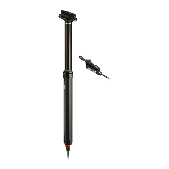
- Page 1 2014 REVERB STEALTH Service Manual...
- Page 2 This warranty does not apply to products that have been incorrectly installed and/or adjusted according to the respective SRAM user manual. The SRAM user manuals can be found online at sram.com, rockshox.com, avidbike.com, truvativ.com, or zipp.com. This warranty does not apply to damage to the product caused by a crash, impact, abuse of the product, non-compliance with manufacturers specifications of usage or any other circumstances in which the product has been subjected to forces or loads beyond its design.
-
Page 3: Table Of Contents
TABLE OF CONTENTS EXPLODED VIEW - REVERB STEALTH ............................5 ROCKSHOX REVERB STEALTH SEATPOST SERVICE ......................... 6 PARTS AND TOOLS ............................................. 6 REVERB STEALTH DISASSEMBLY ........................................ 8 TOP CAP ASSEMBLY SERVICE ........................................16 REVERB STEALTH REASSEMBLY ........................................ 21 REMOTE AND HOSE BLEED .......................................... 27... - Page 4 SAFETY FIRST! We care about YOU. Please, always wear your safety glasses and protective gloves when servicing RockShox products. Protect yourself! Wear your safety gear!
-
Page 5: Exploded View - Reverb Stealth
Poppet Valve IFP Tube Bottom Out O-ring Poppet Valve Cover Bleed Screw Travel Spacer (not in all configurations) Inner Seal Head Foam Washer Hose Barb Internal Floating Snap Ring Connectamajig Piston (IFP) Hose Strain Relief ExPLODED VIEW - REVERB STEALTH... -
Page 6: Rockshox Reverb Stealth Seatpost Service
R O C K S H O X R E V E R B S T E A L T H S E A T P O S T S E R V I C E We recommend that you have your RockShox Reverb Stealth seatpost serviced by a qualified bicycle mechanic. Servicing RockShox products requires knowledge of suspension components as well as the special tools and fluids used for service. - Page 7 N OT I C E When servicing the Reverb Stealth seatpost, do not scratch any sealing surfaces, the upper post, the inside of the lower post, the inner seal head, or damage any replacement o-rings or bushings. Damage to any of these parts can cause leaks and reduce performance of the seatpost.
-
Page 8: Reverb Stealth Disassembly
C A U T I O N - E Y E H A Z A R D Verify all pressure is removed from the Reverb Stealth before proceeding. Failure to do so can cause the inner seal head and inner shaft to separate from the upper post assembly at high velocity. - Page 9 Open the seatpost clamp or loosen the seatpost collar binder bolt and remove the Reverb Stealth from the bicycle. It is not necessary to remove the Reverb remote from the handlebar unless the remote housing is too short to allow the Reverb to be removed from the frame.
- Page 10 To prevent damage to the poppet cover bleed screw, do not allow the 10 mm wrench to contact the bleed screw. 11 mm 10 mm Use needle nose pliers to pull the poppet valve from the inner shaft. REVERB STEALTH DISASSEMBLY...
- Page 11 Do not scratch any sealing surfaces when servicing your Reverb Stealth. Scratches can cause leaks. Use a pick to remove the bottom out o-ring from the lower post. Clamp the lower post horizontally in a vise with soft jaws. REVERB STEALTH DISASSEMBLY...
- Page 12 Remove the upper post from the lower post. 355 & 420 mm Reverb Stealth with 100 mm travel, and 420 mm Reverb Stealth with 125 mm travel: Use a long wooden or plastic dowel to push the false bottom insert from the lower post.
- Page 13 Be careful not to scratch the inner shaft as this is a critical sealing surface. 23 mm Remove the inner seal head from the upper post by hand. REVERB STEALTH DISASSEMBLY...
- Page 14 Use pliers to carefully pull the IFP tube out of the upper post. 1.5 mm Remove the upper post from the vise and pour the fluid into a container. Clamp the post head back into the vise with soft jaws. REVERB STEALTH DISASSEMBLY...
- Page 15 Insert seven to nine 20 cm long cable ties, one at a time, into the upper post through the IFP. Pull all of the cable ties simultaneously out of the upper post, removing the IFP in the process. REVERB STEALTH DISASSEMBLY...
-
Page 16: Top Cap Assembly Service
N OT I C E Use caution when servicing the Reverb Stealth seatpost not to scratch any sealing surfaces, being especially careful not to scratch the upper post, the inside of the lower post, the inner seal head, or damage any o-rings or bushings. - Page 17 Soak a new foam ring in Reverb Hydraulic Fluid. Install it into the top cap above the bushing. Carefully remove the energizer ring from the new dust wiper. Insert the small end of the new dust wiper into the end of the lower post.
- Page 18 Use your fingers to remove the o-rings from the seal head. Clean any dirt or debris from the seal head, and install new o-rings. Use your fingers or a pick to remove the o-rings from the poppet valve. Clean the poppet valve, then install new o-rings. TOP CAP ASSEMBLY SERVICE...
- Page 19 Use your fingers to remove the two backup rings and the o-ring from the inner shaft piston. Use a pick to remove the poppet o-ring from inside the main piston, then install a new o-ring. Clean the inner shaft piston and install two new backup rings and a new o-ring.
- Page 20 Remove the bushing from the inner seal head by hand. Use your fingers or a pick to remove the two external o-rings, the internal U-cup, and the internal top out bumper. Be careful not to scratch any of the surfaces of the inner seal head. Clean the inner seal head.
-
Page 21: Reverb Stealth Reassembly
Pour Reverb fluid into the IFP tube until the fluid overflows into the upper post and is level with the top of the upper post. Use your finger to remove any bubbles from the surface of the Reverb fluid. REVERB STEALTH REASSEMBLY... - Page 22 If the inner shaft does get pressed into the IFP tube, the inner shaft must be removed from the IFP tube (steps 23-24, page 13, and step 25, page 14), the IFP tube filled with additional Reverb fluid (step 4, page 21), and the inner shaft reinstalled (steps 6-7, page 22). REVERB STEALTH REASSEMBLY...
- Page 23 Install a new bottom out bumper into the lower post. 355 & 420 mm Reverb Stealth with 100 mm travel, and 420 mm Reverb Stealth with 125 mm travel: Apply SRAM Butter to the false bottom insert o-ring, then install it into the lower post.
- Page 24 5.7-7.9 N•m (50-70 in-lb) A specific amount of Reverb fluid must be removed from the inner shaft. Consult the chart below and set the fluid level height for your Reverb Stealth. Reverb Model Set fluid level gauge to this Length (mm)/ Travel (mm) length (±...
- Page 25 N OT I C E To prevent damage to the poppet valve cover bleed screw, do not allow the 10 mm crowfoot socket to contact the bleed screw of the poppet valve cover. 10 mm 11 mm 5.7-7.9 N•m (50-70 in-lb) REVERB STEALTH REASSEMBLY...
- Page 26 90 degrees to the torque wrench. 34 mm 27-29 N•m (238-256 in-lb) Use a shock pump to pressurize the seatpost to 250 psi (17.2 bar). Use a 9 mm socket to reinstall the air cap. 250 psi (17.2 bar) 9 mm REVERB STEALTH REASSEMBLY...
-
Page 27: Remote And Hose Bleed
R E M O T E A N D H O S E B L E E D Standard: Thread the hose barb into the poppet valve cover. Hold the hose barb in position with a 7 mm open end wrench, and use a 10 mm crowfoot wrench to tighten the poppet valve cover to 3.4-4.5 N•m (30-40 in-lb). - Page 28 N OT I C E Only use the syringes that come with the Reverb Stealth Bleed Kit. Do not use any syringe that has been in contact with DOT fluid. Use a T10 TORx to remove the bleed screw from the remote.
- Page 29 Pull back on the actuator. If it doesn't move, you have successfully bled the remote and are finished servicing your Reverb Stealth. If a gap is present, repeat remote bleed steps 5-11, pages 28-29.
- Page 30 Reinstall the Reverb Stealth into the bicycle frame. Tighten the seatpost collar to the manufacturer's recommended torque, but do not exceed 6.7 N•m (59.3 in-lb). 4 mm 2.2 N•m (19.5 in-lb) Reinstall the saddle and saddle clamps onto the seatpost. Use a 4 mm hex wrench and tighten the saddle clamp bolts to...
- Page 31 www.sram.com GEN.0000000004211 Rev C © 2015 SRAM LLC...
Need help?
Do you have a question about the Reverb Stealth and is the answer not in the manual?
Questions and answers