
Summary of Contents for Purafil ONGUARD SMART
- Page 1 USER MANUAL ® ONGUARD SMART 2654 Weaver Way | Doraville, GA 30340 | Office: 770.662.8545 | www.purafil.com | OnGuard Smart Manual - 01...
- Page 2 Nuclear Fuels, U.K.; Honeywell, Yokogawa, and Georgia Pacific, USA. Purafil thanks you for your purchase and we know you will be as pleased with your OnGuard unit as we are with its development. For additional information or questions on the product contact: Purafil, Inc.
-
Page 3: Table Of Contents
Configuration ............................ 20 Clock/Calendar ..........................20 Temperature, Relative Humidity and Pressure ................21 Sensors ............................21 Calibrate Temperature, Relative Humidity and Pressure ..............22 2654 Weaver Way | Doraville, GA 30340 | Office: 770.662.8545 | www.purafil.com | OnGuard Smart Manual - 01... - Page 4 Plus and Minus Keys ..........................33 Step Amount ............................. 33 Store Changes ............................34 Procedure ............................34 Frequently Asked Questions ......................35 2654 Weaver Way | Doraville, GA 30340 | Office: 770.662.8545 | www.purafil.com | OnGuard Smart Manual - 01...
-
Page 5: The Onguard Technology
OnGuard 1000, with significant improvements in user interface, accuracy, and application flexibility. The OnGuard Smart implements the most desired features of the OnGuard 2000, 3000, 4000 adding pressure measurements and Wi-FI Ethernet communications. In addition, the OnGuard Smart is housed in an attractive enclosure that can address a variety of markets. -
Page 6: How The Onguard Works
How the OnGuard Works Technology Corrosion on electronic components and contacts and on precious and semiprecious metal artifacts is characterized by the buildup of various chemical reaction products (films) which form when corrosive gases come into contact with the base metal. -
Page 7: Temperature Effects On Corrosion
Temperature Effects on Corrosion Increases in Temperature can accelerate the rate of corrosion by increasing chemical reactions. Using the OnGuard to monitor and record Temperature, increases or decreases in Cumulative Corrosion and Incremental Corrosion can be correlated to Temperature effects. The Temperature sensor is read continuously, and the data is averaged over a one- minute time period. -
Page 8: Unpacking And Inspection
Purafil. Fill out the Warranty Registration Card and return it to Purafil immediately. Failure to send in the Warranty Registration Card may result in delayed receipt of future updates to OnGuard and may limit technical support. -
Page 9: Installing And Powering The Onguard
READ THIS BEFORE YOU CONTINUE When setting up the OnGuard, after powering it and initializing the sensors, please contact your IT department to help with connecting the OnGuard to a network and setup. Installing and Powering the OnGuard Although the OnGuard is designed to withstand corrosive industrial environments, the unit contains sensitive electronic circuitry. -
Page 10: Initializing Sensors
When the batteries are installed reassemble the case by installing the two screws that were removed to open the case. Initializing Sensors When the OnGuard is shipped from the factory, it is enclosed in a protective bag designed to minimize contaminant access to the corrosion sensors. -
Page 11: Local Area Network Connection
Local Area Network Connection By default, DHCP is enabled on the OnGuard. This means that it will acquire an address (dynamically) from the local network router as soon as it is plugged into a network. The new address is displayed on the OnGuard’s LCD screen for about 10 seconds whenever the Ethernet connection is made or disconnected. - Page 12 In this case, to connect to this OnGuard’s web interface, type “192.168.2.103” into your browser’s address bar. Below shows the home page of this OnGuard at address 192.168.2.103:...
-
Page 13: Static Address
Note that the dynamic address may change. If the OnGuard or the network router is power-cycled, the OnGuard may be assigned a different address. Exact behavior will depend on the network router’s (or local DHCP server’s) configuration. Static Address There are two methods to set a static address for an OnGuard device. The preferred method is to configure the local router (or DHCP server) to assign the same address to the device every time it registers on the network. -
Page 14: Non-Preferred Method
Enter this address in your router DHCP configuration with a desired address in order to specify a fixed address for the OnGuard. Exact method will depend on the router’s make and model, but this is typically found in its settings page under Configuration->Advance->DHCP. -
Page 15: Direct Connection (No Network)
Click “Enable DHCP” so that it is not checked, then enter the desired address in the “IP Address” field. Click “Save Config” to save the settings. The device will reboot and then you must point your browser to the newly assigned address. The device’s address is displayed on the OnGuard’s network menu as shown below and may be accessed by scrolling through the menus using the devices “Menu”... - Page 16 Double-click Network Connections. Right-click the Local Area Connection icon, and then choose Properties.
- Page 17 On the General tab, highlight Internet Protocol (TCP/IP), and then click Properties. Click “Use the following IP address:” button and enter 192.168.2.99. Click “OK”. A message asking for the “subnet mask” will pop-up. Click “OK” and the subnet mask should populate itself. Pressing the Tab button on your keyboard should also auto fill the subnet mask field.
- Page 18 Then connect the OnGuard to the computer using a standard Ethernet cable. The OnGuard is programmed to default to 192.168.2.77 when no DHCP server is found. Point your browser to 192.168.2.77 to access its web interface. Once the configuration is complete, you will need to return the local area connection to the default settings. Return to the local area Ethernet connection that was changed, open its properties and select “Obtain an IP address automatically.”...
-
Page 19: Wireless Settings
Wireless Settings The OnGuard is designed to communicate through an internal web interface, via Wi-Fi, for setup and logging purposes. Remember to power the OnGuard in one of the two external ways before trying to connect. The OnGuard will display the available networks. Clicking on one of the networks will establish a connection. Configuration The OnGuard may need to be configured to operate properly in your location, and provide the data desired. -
Page 20: Clock/Calendar
Ethernet section. A summary of the available functions is listed below: Clock/Calendar Tab The date and time must be set. Make sure the OnGuard is powered and connected to the Ethernet and communication established. Once the web interface is accessed, click on the “Settings” tab. Enter the time and date in the spaces provided and click the “Set”... -
Page 21: Temperature, Relative Humidity And Pressure
Temperature & Humidity The OnGuard allows you to set high limit, low limit, and rate-of-change limits for temperature and relative humidity. When limits are exceeded, the red LED will flash on the OnGuard as well as an indication of alarm on the web interface. To access alarm settings for temperature and humidity click on the Settings tab and changes can be made in the environment box. -
Page 22: Calibrate Temperature, Relative Humidity And Pressure
Calibrate Temperature & Humidity The temperature and relative humidity sensors can be calibrated from the OnGuard website. Under the “Settings” tab, there are selections for calibrating temperature and calibrating humidity. A reference instrument is required to provide a point to calibrate to. The temperature can be calibrated in Celsius or Fahrenheit. To calibrate temperature, click on the link “Calibrate”... - Page 23 To calibrate humidity, click on the link “Calibrate” within the humidity box. A window will pop-up with instructions and field for input. Calibrate Pressure The pressure sensor can be calibrated from the OnGuard website. Under the “Settings” tab, there are selections for calibrating pressure.
-
Page 24: Data Logger
Data Logger The data logger can be enabled and disabled from the logger tab (screen below). Setup The logger interval can be set from 2 to 120 minutes. When the OnGuard is battery operated, you can maximize battery life by setting the logger interval to a higher value (15+ minutes) as the OnGuard uses more power during readings than between readings, when it “sleeps”. -
Page 25: Pop-Up Data Feature
Pop-Up Data Feature Placing your cursor over specific points along the copper, silver, temperature and relative humidity lines will display data point values. Data Table A table with the raw data from the graph can be accessed by pressing the “Table” tab in the bottom left corner of the window. -
Page 26: Logger Memory
Logger Memory The OnGuard can store over 21,000 readings in its logger memory. Data can be erased using the “Erase” button at the top of the logger window. Below is the logger memory capacity given different log intervals. Log Interval Hours Days 2 Minutes... -
Page 27: Email Settings
Email Settings Basic Settings • Enable E-Mails – Unchecking this will disable emails from being sent by this device • To – The intended email recipient • Test – Check “Send Now” and save changes to send a test email Server Settings The following email settings are required by your email service (gmail, yahoo, Exchange, etc): •... -
Page 28: Email Information
Email Information The alarm email will contain the following information: ------------------------ Device: OG_ROOM185 CURRENT READINGS Local Time: 4/23/14, 15:05:13 ISA Class: Temperature: 27 *C Rel Humidity: 34 %RH Power: External ------------------------ ALARM DETAILS 0: SENSOR_1 Sensor 1 not initialized or Sensor expired 0: SENSOR_2 Sensor 1 not initialized or Sensor expired 0: BATTERY... -
Page 29: Replacing Corrosion Sensors
Replacing Corrosion Sensors When a corrosion sensor reaches its end of life, which happens when it reaches 4000 Angstroms of corrosion accumulation, it will cease to function and must be replaced. When a replacement sensor is obtained, install it on the OnGuard in the same place as the sensor that failed. -
Page 30: Appendix
Appendix OnGuard LCD Menus The OnGuard contains a backlit graphic LCD Display. The primary information screens are the “Network Menu” and the “Main Menu”. Additional screens are available to display alarm conditions, data logger settings and the OnGuard’s firmware revision. These are the “Alarm Menu”, the “Logger Menu”, and the “Version Menu”. The user can sequentially cycle through all these screens by pressing the “Menu”... -
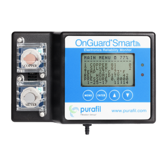
Page 31: Main Menu
ALARM MENU ------------------------ TEMP OK RELH SENS OK BATT OK Alarm Menu The Alarm Menu shows the status of the OnGuard sensors and the main power batteries. The status of each will be shown as “OK” unless there is a problem with one of them. When an alarm condition occurs the red LED will light. The temperature (TEMP) and relative humidity (RELH) sensors will show an “L”... -
Page 32: Ma Calibration
OnGuard® Smart 4-20 mA Calibration Introduction The OnGuard is capable of 4-20 circuit calibration through the internal web interface. The 4-20 circuits are set by firmware default values such that the current loop levels will be very close to 4 and 20 milliamps on average. However, due to slight performance differences in electronic components, the firmware default levels may not be close enough for a particular application. -
Page 33: Output
Output Selecting any of the outputs (Channel 1 through Channel 4) will force the currently selected level (Minimum or Maximum) to be output on the selected channel. Level Selecting either option (Minimum or Maximum) will force the currently selected channel to its minimum or maximum level. -
Page 34: Store Changes
Store Changes This stores the changes for the currently selected channel and level. For example, if Channel 1 and Maximum are selected, clicking Store Changes will store changes made to the maximum level of channel 1, channel one’s minimum level and the other channel calibrations will not be stored. This allows the user to change any single attribute of each channel’s minimum and maximum levels;... -
Page 35: Frequently Asked Questions
What are the different methods by which the unit can be powered? The OnGuard Smart can be powered by batteries (4 AAs), POE (power over Ethernet) and 25v DC. What are the different methods by which I can view the data? Data can be viewed locally with the LCD, on a network with a computer or through a DCS (distributed control system) or BMS (building management system). - Page 36 Does the unit use battery power when connected tow Wi-Fi? Battery power is not suggested when the OnGuard Smart is connected to a network by Wi-Fi or cable due to power consumption. Power Over Ethernet (POE) is suggested for directed connections and 24v DC is suggest when Wi-Fi is used.
- Page 37 The copper or silver sensors do not require calibration, they are factory calibrated. The email alter feature is not working. Connect to the OnGuard Smart and go to the Email Settings Tap (see manual page 26) and check address settings.
- Page 38 ISA Standard (S71.04) generally have background reading from 50 to 150 angstroms. The coupon value should be corrected for background corrosion before making any comparisons. What if the OnGuard Smart has been moved to a new location and the corrosion values seem to have changed? The OnGuard Smart is designed to be permanently mounted.
Need help?
Do you have a question about the ONGUARD SMART and is the answer not in the manual?
Questions and answers