Table of Contents
Advertisement
Advertisement
Table of Contents

Summary of Contents for Signal SDS Series
- Page 2 Introduction Thank you for purchasing a SIGNAL SDS Series irrigation controller. The SIGNAL SDS Series is an Australian designed and manufactured irriga- tion control system, designed for ease-of-use programming, while allowing for the complex requirements of both landscape and agricultural applica- tions.
- Page 3 Safety Information SDS Series The SDS Series of controllers are designed to operate on low voltage 36VDC. Use only the power supply included with the controller. The power supply must be installed to comply with local electrical codes. Prior to digging or trenching check with your local utilities for any under- ground services.
- Page 4 Two-Wire Devices, introduction Water meter Pulse Resolution, introduction KWH Meter Resolution, introduction Two-Wire Programming Port, introduction Quick start programming Menu Path of SDS Series SDS Series Short-Cuts Basic Time Based Program Manual - start/stop program, start/stop stations 23-24 Manual - run valves...
-
Page 5: Table Of Contents
SDS Series Index Manual Functions Start Program, manually Stop Program, while running Pause Program View Active Program Start Stations, manually Stop Active Stations Information Log, view Log, delete Faults, system Water Meter Count, total Water Meter Flow, active Power Meter, total... - Page 6 SDS Series Index Leak Detection Level Sensor, SDS-100 Only Weather Stations, evapotranspiration View Inputs HydroSector Programming HydroSector, introduction HydroSector, flow chart HydroSector, steps Converting Programs to HydroSectors Auto-Programming Feature HydroSector, active days & accepting master start times 48-49 Factory Default Settings...
- Page 7 DataCoil™ is a combined solenoid coil and two-wire decoder. Connects directly • to the two-wire cable. • SDS Series can operate conventional (multiwire) solenoids using RelayCubes. This can be done in conjunction with two-wire DataCoils when required. RelayCube 1: Outputs 01—24 RelayCube 2: Outputs 25—48 RelayCube 3: Outputs 49—72...
- Page 8 Description SDS Series 8 Independent programs with flexible pump assignment • 12 Programmable field DataNodes™ connect directly to the two-wire cable • • Moisture sensors (up to 4 total) Water meters ( up to 8) • Pause program • •...
- Page 9 Description SDS Series 0.25 Hz max 0.25 Hz max...
- Page 10 Circuit board LED indicators SDS Series CHECKING CIRCUITRY FOR FAULTS: Led 1 = Power OK at Motherboard Led 2 = Power OK at Micro Controller Board Led 3 = (Flashes) = Micro Controller is OK Led 4 = Power OK at Output Board...
- Page 11 Description SDS Series SDS SERIES ENCLOSURE & MOUNTING:...
- Page 12 Enclosure SDS Series Dimensions: 179H x 199W x 106.5D Front lid hinges up 90° and 180° Clear view window Easily accessible terminal strip...
- Page 13 SDS Series Enclosure (NEW) CLIP-ON FRONT PANEL Push down to secure • Pull up to remove • Screw down at bottom •...
- Page 14 SDS Series Installation INSTALLATION GUIDE:...
- Page 15 SDS Series Installation Two-wire DataValves and direct wired solenoid valves can operate simul- taneously. To field two-wire devices The SD-DR-1 relay module (RelayCube) can be connected anywhere along the two-wire cable network. A separate 24 volt AC power supply is re- quired to provide power to standard 24VAC solenoid coils.
- Page 16 Avoid close proximity to possible electromagnetic interference and particularly • close proximity to VSD devices unless they meet all the manufactures installation requirements. Signal Data Systems recommend a distance of 5 meters from possible sources of electromagnetic interference. MOUNTING CONTROLLER: Locate at an easy viewable eye level with a minimum top clearance of 200mm •...
- Page 17 TWO-WIRE CABLE REQUIREMENTS: Signal twisted pair cable with tinned copper conductors certified for direct burial • is recommended for optimum performance. Signal recommends all two-wire cable joints should be soldered in a professional •...
- Page 18 SDS Series Programming intro. PROGRAMMING INTRODUCTION: The key pad is a soft touch design with a audible beep to confirm contact. If a key is held down it will fast repeat. This is most helpful in the Scroll and Back keys.
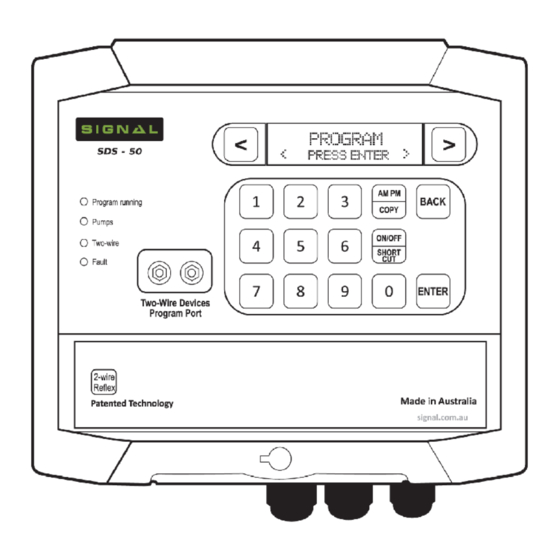
- Page 19 Programming intro. SDS Series The SDS-50 controller has a two-wire output that supplies electrical power and a communica- tion protocol to operate up to 48 DataValves™ and up to 12 DataNodes™. In addition it is supplied with a pump start PumpNode™. The default address for this device is set at 49. The controller can operate an auxiliary pump which is typically used for chemical or fertiliser dos- ing.
- Page 20 Programming intro. SDS Series CONTROLLER TWO-WIRE PROGRAMMING PORT: (All two-wire devices configuration are programmed from this port, or the optional hand-held programmer) DataCoil wire colour may vary depending on model.
- Page 21 Quick Start Programming SDS Series MENU PATH OF SDS SERIES: PROGRAM COMMUNICATION Program Entry Wi-Fi Mode Pause Program Wi-Fi SSID Rain-Off Program Wi-Fi Passkey Program % Change Device ID Clear Program Device Password HydroSector Prg SMS Users WM Configuration TWO-WIRE...
- Page 22 Quick Start Programming SDS Series SDS SERIES MENU SHORT-CUTS: View Program Status: From the current Time P1 2 3 4 5 6 7 8 and Date display press A A P P R R f f Note: A = Active, P = Paused, R = Rained-Off, F = Frost Program Setup + Enabled...
- Page 23 Quick Start Programming SDS Series QUICK START PROGRAMMING: For a basic time based program running one pump or master valve with the correct current time and date already set on the controller - Follow the easy step by step guide below to get...
- Page 24 Quick Start Programming SDS Series MANUALLY START/STOP STATIONS: Manual Start Prg MANUAL/TEST < Press Enter > < Press Enter > Select station numbers Set From / End Stn Manual Start Stn from keypad From ## End ## < Press Enter >...
- Page 25 SDS Series Programming SETTING TIME & DATE: Current day Date On first powering up, the time will need to be set to your current time and date. The controller will display this Current time TIME & DATE Enter The Time <...
- Page 26 SDS Series Programming Enter time with numer- Continue with <P# WaterStn ic keys Hr:min:sec run time entries 00 : 00 : 00 100% Enter delay with numeric P# Station Delay To copy run times keys (30 sec max’). to next stns...
- Page 27 SDS Series Programming LOOP PROGRAMS continued Return to Date Start Time Overlap Current Water % Time display 100% NONE FROST PROGRAM DESCRIPTION: The controller uses program 7 and 8 for frost control. In the [TWO-WIRE] menu, two frost sensors (1 and 2) are available to assign to DataNodes. Sensor 1 will activate program 7 and sensor 2 will activate program 8.
- Page 28 SDS Series Programming FROSTWATCH MONITORING TIME-WINDOW: From the current Time SYSTEM SETTINGS and Date display scroll < Press Enter > FrostTime Start Use numeric keys to Frost Watch On enter time h/m/s < Press Enter > 00 : 00 : 00 Am...
- Page 29 SDS Series Programming WATER METERS: The controller supports up to 8 water meters. Water meter (1) assigned to all programs as default setting. This is the [WMD] input terminal on the controller. This is also the only water meter which will display LIVE FLOW through the controller.
- Page 30 SDS Series Programming WATER METERS - ASSIGNMENT TO PROGRAMS: (default is WM1 for all programs) Begin in Program Entry WM Configuration PROGRAM menu < Press Enter > < Press Enter > Use numeric keys to select the program. Use Program No. # <...
- Page 31 SDS Series Programming Note: The auxiliary pre-wet is the time that the station runs without the dosing (auxiliary) pump running. The auxiliary run time is the dosing pump run time during the stations watering time. The balance of the time on the stations watering time is a post-wash time.
- Page 32 SDS Series Programming STATION RUN TIME % CHANGE: Percentage change will increase or decrease the station run times in the program/s selected. The original programmed time is 100% From the current Time Program Entry PROGRAM and Date display, scroll <...
- Page 33 SDS Series Programming VIEW PROGRAMS RUNNING: Operating program/s will indicate with a flashing program number/s on the display. M# @100% Enter program num- Running Programs Display will ber from keypad. Stn. # 00 : 00 : 00 Flash 1 # # # # # # #...
-
Page 34: Stop Program, While Running
SDS Series Programming MANUAL / TEST MANUALLY START A PROGRAM: From the current Time Manual Start Prg MANUAL/TEST and Date display scroll < Press Enter > < Press Enter > < > Program Type to select Normal Program or HydroSector <... -
Page 35: Information
SDS Series Programming INFORMATION VIEW LOG: Up to 999 events are held in memory From the current Time INFORMATION and date display scroll < Press Enter > < > Use scroll keys Date Time View Log to view Event <... -
Page 36: Power Meter Total
Wa- INFORMATION ter Level display. Shown as % 000% < Press Enter > Note: Only available in SDS-100. Requires Signal ultrasonic level sensor. MOISTURE READING: < > keys to advance to Mois- INFORMATION > ture Reading display Enter. -
Page 37: System Settings
SDS Series Programming SYSTEM SETTINGS WATER METER PULSE: Note: It is necessary to set the pulse ratio to match the water meter output pulses From the Time and Flow Meter Pulse SYSTEM SETTINGS Day display scroll < Press Enter >... -
Page 38: Delay Time, Introduction
SDS Series Programming DELAY TIMES: This menu has three delay parameters. Pressure Delay, Water Flow Delay and Last Station On Delay. PRESSURE DELAY: An analog pressure sensor connected to the [PRE] terminal at the controller, or digital sen- sors connected to the [HP] - [SP] and [LP] terminals, will stop all irrigation after a pre-set time delay on Low and High pressure. -
Page 39: Two-Wire Devices
SDS Series Programming TWO-WIRE DEVICES VIEW VALVES ONLINE: This is the field DataValves™ messaging back as on-line and communicating From the Time and TWO-WIRE Valves Online < > Date display use < Press Enter > < Press Enter > ## VALVES ONLINE Current valves on-line will display. -
Page 40: Datavalve/Pumpnode Address, Programming
Programming SDS Series DATAVALVE & PUMPNODE ADDRESS NUMBER PROGRAMMING: To program a DataValve or PumpNode number. Connect the valve or PumpNode to the Two- Wire Devices Program Port or Mobile Programmer, using the supplied leads. Caution: Ensure programming is correct before disconnecting from the program port. -
Page 41: View Datanodes
Programming SDS Series Con’t Moisture sensor pre-set irrigation override setting, see page 43. Stop Program this is linked to the Start Program input sensor at the controller i.e. pro- gram/s started by the Start Program input sensor are stopped by the Stop Program sensor. -
Page 42: Inputs
If this is the case, the time for the electrical signal to be initiated and a valve to electrically and hydraulically respond may be beaten by the high pressure cut-out. A pressure sustaining/relief valve can be installed that is sized to slow down the pressure increase if a valve fails to open but not completely prevent a pressure increase that would override a HP cut-out in a closed head condition. -
Page 43: Pause Sensor
Programming SDS Series PAUSE SENSOR: This sensor will pause its selected programs when running. The programs will resume at the paused state when the sensor is de-activated. From the Time and INPUTS Pressure Sensor date display scroll < Press Enter >... -
Page 44: Set Station Flow
> LEVEL SENSOR: Available on the SDS-100. This feature is used with the Signal Flomag Ultrasonic Level Sensor. Instructions on how to operate included with the sensor. Possible functions are: 1) Tank Fill 2) Pause/Resume Irrigation 3) Shutdown program on low level 4) View live tank level display. -
Page 45: Weather Stations, Evapotranspiration
Programming SDS Series WEATHER STATION: Program adjustments via Weather Station evapotranspiration is available by connecting a Sig- nal WeatherHawk Weather Station to SignalCloud. Instructions available separately with weather station purchase. VIEW INPUTS: (inputs within the physical terminal strip) From the Time and... -
Page 46: Hydrosector Programming
Programming SDS Series HydroSector™ PROGRAMMING: HydroSector™ INTRODUCTION: The HydroSector program is a conversion of the standard irrigation programs • into a linked sequence of matched-precipitation HydroZones. Each Zone would typically be a number of matched precipitation stations. For example, program 1 would become matched precipitation zone 1, program 2 would become matched precipitation zone 2, etc. -
Page 47: Hydrosector, Steps
Programming SDS Series HydroSector™ STEPS: Check the current station/valve wiring within the [TWO-WIRE] then [>] [Assign Valves] menu. When using HydroSectors, stations should be wired sequentially. For ex- ample, a typical system may be set up as follows: HydroSector 1 using stations 1—10, HydroSector 2 using stations 11—20 and so on. -
Page 48: Auto-Programming Feature
Programming SDS Series AUTO-PROGRAMMING FEATURE: The auto-programming option assigns time or volume of water to each valve & stn within the HydroSector from a total value entered for each H/Sector. If Auto programming is not selected go to Program Entry display and program as normal. -
Page 49: Factory Default Settings
Programming SDS Series < > If required use numeric keys to H# Station Delay keys to enter station delay mins : secs. view stations 00 : 00 Ms H# Total Water 00 : 00 : 00 If the auxiliary pump option is used the following will display. -
Page 50: Fault Finding
Fault Finding SDS Series FAULT FINDING THE CONTROLLER: SDS Series controllers have been designed for simplified service and repair. The controller does not require a service technician for on-site electronic repair - instead utilising plug-in replacement PCB modules. The principle components of the controller consist of: A mother board which contains the internal PCB power supply, lightning protec- tion and plug-in module interfaces. - Page 51 Fault Finding SDS Series If it is suspected a fault is present at the controller and not in the field cabling or DataValves, proceed as follows: Remove the four front keypad panel screws and carefully lift to one side, press any key on the keypad to ensure the output is switched on.
-
Page 52: Current Draw, Datacoils
Fault Finding SDS Series CURRENT DRAW: DataCoils draw current as follows: SD2NC: Idle = 1.5 mA | Running = 16 mA SD3NO: Idle = 1.5 mA | Running = 21 mA SD3LT: Idle = 1.5 mA | Running = 1.5 mA If a total current draw exceeds 1500mA, the controller will indicate a short circuit condition. -
Page 53: Fault Finding Field Valves And Cable, Illustration
Fault Finding SDS Series... -
Page 54: Fault Finding Two-Wire Devices
This fault finding operation requires a clamp-on milliamp meter with a range down to 20 milliamps and a SIGNAL two-wire fault finding tool (SD-RB). If this is not available, in an emergency, a suitable 5-10 watt 250 Ohm wire wound resister can be connected in series with the two-wire cable. -
Page 55: Tracing The Source Of A Short Circuit, Illustration
Fault Finding SDS Series... - Page 56 Fault Finding SDS Series...
-
Page 57: Additional Fault Finding
Fault Finding SDS Series ADDITIONAL FAULT FINDING: On initial installation, great care should taken to avoid grit contamination entering the Data- Coil plungers. Ensure the system is properly flushed before start-up to avoid dirt/grit contam- ination of the piping. If a coil malfunctions, but is still reporting as online with the correct LED indication, it is al- most certain that the coil plunger is jammed by grit. - Page 58 Fault Finding SDS Series Con’t View Valves On-line at control- A valve will not activate Faulty field wire connector or ca- ble damage ler to determine position of cable fault. Valve not assigned Check Assign Valve at controller Faulty DataValve Inspect valve LED indictors for correct operation.
- Page 59 Cable Size Guide SDS Series The model SDS-50 controller has a maximum capacity to operate 4 valves at one time with an additional master valve or pump. The chart below is based on model SD2NC DataCoil™ The chart shows the varying degree of performance in relationship to number of valves run- ning, cable size, distance and operating pressure.
-
Page 60: 3G/4G Modem
Next, plug your Wi-Fi Module into the RS-232 port underneath your controller. Once you do so, the little green LED should begin to flash rapidly. To connect your SDS Series controller online with the Wi-Fi module, the following fields need to be completed: Set WiFi SSID, WiFi Passkey, Device ID and Device Password. -
Page 61: Entering Information Via Keypad
The password to your Wi-Fi network. Device ID: This is the 16 digit Device ID provided to you by SIGNAL. Device ID’s are case-sensitive. SDS owners can currently select their own – simply choose a descriptive site code. Device Password: User set password - Must be 6 letters or digits. - Page 62 SDS Series Site Notes Site: Address no: GSM/3G: DataNodes Valve/s Valve/s NOTES. Default pump settings...
-
Page 63: Hydrosector, Notes
SDS Series Site Notes HydroSector Program Tick starts selected Tick days on 1 2 3 4 Total run time Total litres Precipitation: mm HydroSector Master Start times Australia and International New Zealand Distributed by: Distributed by: Technical Irrigation Imports Willowbank Electronics Ltd... - Page 64 Signal Data Systems Manufactured in Australia www.signal.com.au...
Need help?
Do you have a question about the SDS Series and is the answer not in the manual?
Questions and answers