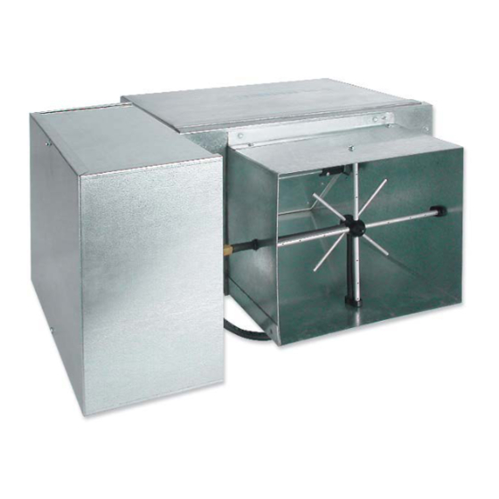
Summary of Contents for Johnson Controls TSS
- Page 1 SINGLE DUCT VAV TERMINALS INSTALLATION, OPERATION & MAINTENANCE Form 130.13-NOM1 (114) New Release MODELS TSS & TSL...
-
Page 2: Table Of Contents
Checkout Instructions ...........................8 Damper Shaft ............................8 Coil ................................8 Cleaning ............................9 Electric Heat ............................9 Minimum Operating Conditions ......................9 Electric Heater Rack Replacement ....................9 Electric Heater Element Replacement ....................9 Heater Troubleshooting Guide ......................10 (SSR) Troubleshooting Guide ....................... 11 Calibration Charts ..........................15 JOHNSON CONTROLS... -
Page 3: Safety Considerations
Protect adjacent flammable material when brazing. Use flame and heat Check that rigging and lifting equip- protection barriers where needed. ment can safely support the unit as- Have fire extinguisher ready for im- sembly and component weights. mediate use. JOHNSON CONTROLS... -
Page 4: Inspection
Also ensure that unit voltage agrees with the ready for immediate use. building parameters. If a discrepancy is discovered between what was ordered and received, contact your local Johnson Controls representative immediately. STORAGE If equipment is to be stored prior to installation, observe the following precautions: DO NOT USE FLOW SENSOR, 1. -
Page 5: Pre-Installation Inspection
Suspension devises are field supplied, sized and come in rectangular and round. The round valves only designed by others. Johnson Controls will not accept come in diameters of 4, 5, 6, 8, 10, 12, 14 and 16 inches; responsibility for unit support. Equipment must be an adapter must be used for metric ductwork. -
Page 6: Unit Weights
FORM 130.13-NOM1 (114) UNIT WEIGHTS TABLE 1 - SINGLE DUCT TERMINAL UNIT WEIGHTS TABLE 2 - TSS WATER COIL WEIGHT ADDS UNIT TSS w/ SA TSS w/ EH # OF ROWS UNIT SIZE SIZE SINGLE DOU- SINGLE DOU- SINGLE DOU-... -
Page 7: Critically Sound Applications
Electrical and/or control wiring diagrams are and balancing information. located on the control enclosure box. All electric heaters are staged per specifications. The installing electrician should rotate the incoming electric service by phase to help balance the building electrical load. JOHNSON CONTROLS... -
Page 8: Maintenance
Fin edges are sharp. Fins are fragile; care must be exercised to avoid damag- ing fins. Do not use solutions to clean coils; drain pans are not present to remove collected solution. JOHNSON CONTROLS... -
Page 9: Cleaning
5. Insert new element rack into control enclosure and replace screws to secure the element rack to control Electric Heat enclosure. Johnson Controls electric heaters require little or no 6. Replace wires. maintenance. 7. Close control enclosure cover before turning on the power. -
Page 10: Heater Troubleshooting Guide
FORM 130.13-NOM1 (114) ELECTRIC HEATER TROUBLESHOOTING GUIDE JOHNSON CONTROLS AND TUTCO TABLE 6 - HEATER TROUBLESHOOTING GUIDE Check wiring diagrams to ensure that heater is properly wired. SYMPTOM POSSIBLE CAUSE CORRECTIVE ACTION Check Disconnect. No Power Check Control Signal (i.e. 24 VAC). -
Page 11: (Ssr) Troubleshooting Guide
FORM 130.13-NOM1 (114) PROPORTIONAL HEAT CONTROL (SSR) TROUBLESHOOTING GUIDE Johnson Controls Heaters Lethal voltages are present in the 6. If the module provided is an ETPHCC or ET- PHCC1, go to step 7. Apply “Pulse” Input per heater control enclosure. Use extreme table above. - Page 12 Briefly reapply power. If the section of heat under test now energizes, the SSR is defective. If heater still will not energize, one of the heater safety devices (limits, safety contactor or airflow switch) or elements is defective. JOHNSON CONTROLS...
- Page 13 FORM 130.13-NOM1 (114) PROPORTIONAL HEAT CONTROL (SSR) TROUBLESHOOTING GUIDE Tutco Heaters, All Power Modules JOHNSON CONTROLS...
- Page 14 FORM 130.13-NOM1 (114) PROPORTIONAL HEAT CONTROL (SSR) TROUBLESHOOTING GUIDE Tutco Heaters, R820 SCR’s JOHNSON CONTROLS...
-
Page 15: Calibration Charts
Fl ow St ar Cal i br at i on Char t FlowStar Calibration Chart (For dead-end differential pressure transducers) (For dead-end differential pressure transducers) Electric Heat Operating Range M odel TSS Model TSS 400 SERIES 7000 SERIES (PNEUMATIC) DDC CONSIGNMENT CONTROLS... - Page 16 FlowStar Calibration Chart (For dead-end differential pressure transducers) Model TSL Electic Heat Operating Range NOTE: Maximum and minimum CFM limits are dependent on the type of controls that are utilized. Refer to the table below for specific values. When DDC controls are furnished by others, the CFM limits are dependent on the specific control vendor that is employed.


Need help?
Do you have a question about the TSS and is the answer not in the manual?
Questions and answers