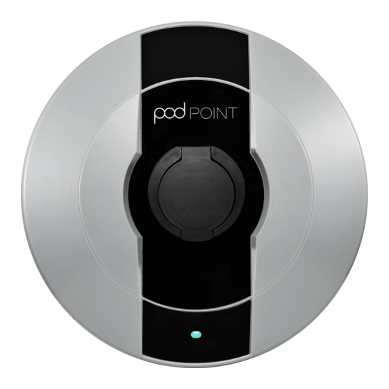
POD Point SOLO Installation Manual
Hide thumbs
Also See for SOLO:
- Installation manual (4 pages) ,
- Connection manual (11 pages) ,
- Connection manual (11 pages)
Advertisement
Quick Links
Pod Point Solo Unit
Installation Guide
Introduction
This guide is intended for
use by competent electrical
installers to understand the
basic requirements and
options to be considered
when installing a POD Point
Solo Mode 3 electric vehicle
charging point. The POD Point
Solo is designed for inside or
outside installations.
Important Safety Information
Warning! The Pod Point Solo charging unit is
manufactured to be safe and without risk provided
it is professionally installed, used and maintained
in accordance with the manufacturer's instructions
and recommendations, It is installed by competent
electrical installers in accordance with national and
local regulations applicable at the time of installation,
Fig. 2
Type A RCD Markings
(gas & water bonding etc.). A minimum of double pole
type A RCD/RCBO must be fitted at source (see Fig 2)
Technical Details
The Point Solo is designed and tested to exceed the
following European standards: IEC61851-1 edition 3
(2017), Low Voltage Directive (LVD) 2014/35/EU and
EMC Directive 2014/30/EU. During manufacture each
POD Point has been functionality tested for safety
using BS EN 61010 & BS EN 61557 approved equipment.
The POD Point Solo is a Class I rated device for 230V /
400VAC 50Hz systems and is IP54 rated. The POD Point
Solo is designed for and Insulation tested to 1500V.
Locating the POD Point Solo
After checking the electrical system is up to date and
is safe to proceed with fitting, the installer should
consult the property owner or user to establish their
preferred installation location and visualise the unit
prior to fitting, considering cable length between the
car and the POD Point and practicalities of the location
(supply cable routing etc.). The installer should confirm
that the structure the unit is intended to be fitted to is
appropriate and decide on the appropriate fixings to
use.
Pod Point Connecting Wi-fi Net work Guide
Fig. 1
Pod Point Solo - Socketed
Version
e.g.: BS7671:2008
Amendment 3:2015. The
POD Point is designed
to be connected to a
dedicated AC supply only.
The electrical installation
where the POD Point
is to be located must
comply with minimum
BS7671 standards before
installation commences
Fig. 3
Dimensions and location of
unit (150mm depth)
150mm
Depth
365mm
750mm - 1200mm
Drilling entry holes for the electrical
supply cable
As the electrical supply to the POD Point Solo may be
from several directions; the unit has been designed to
accept supply cable entry on either the left, right or
bottom sides or via rear entry 20mm "knock outs". The
installer should drill a suitable size hole for the cable
and seal or gland only at these "flat" surfaces provided.
Cable entry holes must not be drilled on any curved
surfaces as this may provide an entry point for water.
Water tight fittings should be used where the POD Point
is placed in exposed locations, Cable entry at the top of
the unit is strictly prohibited.
When drilling the case take care not to damage any
wiring or components inside the unit. Place a suitable
stop (e.g. block of wood) inside the case when drilling
to prevent accidental damage, If any of the wiring
or components are damaged during installation DO
NOT CONNECT OR SWITCH ON THE POWER before
consulting with POD Point.
Fig.4
Drilling Template
1
The POD Point should be
mounted at a height of
750mm-1.2m to comply with
building regulations.
( Fig. 3 ).
Once the location and
height of the POD Point
Solo unit has been decided,
the installer can begin
marking the surface using
the template provided on
the carton insert for the 3
mounting positions
(see Fig. 4).
• Before drilling
commences ensure that
the installation wall has
been checked for electric
cabling or pipework with
a suitable detector.
Additional parts required by
the installer:
1. 3x M8 80mm screws
2. 3x Wallplugs
3. 20mm IP56 or greater
gland for the conduit
entry into the rear unit
housing dependent on
the supply method
(20mm conduit, SWA
armoured cable, flexible
conduit etc.).
Pod Point February 2017
PP-D-130012-13
Advertisement

Summary of Contents for POD Point SOLO
-
Page 1: Important Safety Information
BS EN 61010 & BS EN 61557 approved equipment. or components are damaged during installation DO The POD Point Solo is a Class I rated device for 230V / NOT CONNECT OR SWITCH ON THE POWER before 400VAC 50Hz systems and is IP54 rated. The POD Point consulting with POD Point. -
Page 2: Installation Procedure
Table A. has a PME earthing arrangement where the POD Circuit protection and Power rating settings Point Solo would be connected to a TT system it is imperative that the risk assessment is conducted. If a Circuit Protection Unit Power Rating... - Page 3 450mm and 1200mm above finished floor level to achieve compliance with building Reg’s. A dedicated isolator On power up of the POD Point Solo the LED’s on the front switch is a mandatory requirement for “new builds”, but should illuminate white.
- Page 4 Fig. 8 Unit Label Before Finishing the installation, the power output of the Pod Point Solo needs to be set using the DIP Switch (See Fig.7). Table A (Page 2) illustrates the power settings using the switches 1-3. Electrical Testing...


Need help?
Do you have a question about the SOLO and is the answer not in the manual?
Questions and answers