Table of Contents
Advertisement
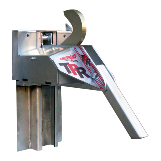
TPR
®
Vehicle Restraint
Owner's/User's Manual
Poweramp • Division of Systems, LLC • W194 N11481 McCormick Drive • Germantown, WI 53022
800.643.5424 • fax: 262.255.5917 • www.poweramp.com • techservices@poweramp.com
Printed in U.S.A.
Manual No. 4111-0035
© 2018 Systems, LLC - All Rights Reserved
Dec. 2018
Advertisement
Table of Contents
Troubleshooting

Summary of Contents for Poweramp TPR
- Page 1 ® Vehicle Restraint Owner’s/User’s Manual Poweramp • Division of Systems, LLC • W194 N11481 McCormick Drive • Germantown, WI 53022 800.643.5424 • fax: 262.255.5917 • www.poweramp.com • techservices@poweramp.com Printed in U.S.A. Manual No. 4111-0035 © 2018 Systems, LLC - All Rights Reserved...
-
Page 2: Table Of Contents
Drive Chain & Brake Torque Adjustments ........26 Adjust Dock Leveler & Vehicle Restraint Interlock ......28 Troubleshooting Limit Switch Test Procedure .............. 30 TPR Harness Wire Identification ............31 TPR Troubleshooting ................32 Parts TPR Carriage Assembly ..............34 Roller Track &... -
Page 3: Precautions
PRECAUTIONS Recognize Precautionary Information General Operational Precautions Safety-Alert Symbol The Safety-Alert Symbol is a graphic representation intended to convey a safety message without the Read and understand the Owner’s/User’s Manual and use of words. When you see this symbol, be alert become thoroughly familiar with the equipment and its to the possibility of death or serious injury. -
Page 4: Operational Precautions
PRECAUTIONS Operational Precautions Learn the safe way to operate this equipment. Read and understand the manufacturer’s instructions. If you have any questions, ask your supervisor. Stay clear of dock leveling device when transport Chock/restrain all transport vehicles. Never vehicle is entering or leaving area. remove the wheel chocks or release the restraining device until loading or unloading is finished, and transport driver has been given... - Page 5 PRECAUTIONS Operational Precautions Do not use dock leveling device if transport vehicle is too high or too low. Do not overload the dock leveling device. Do not operate any equipment while under the influence of alcohol or drugs. Do not leave equipment or material unattended on dock leveling device.
-
Page 6: Safety Decals
• Only authorized personnel who have read and understand File Name: 1751-0736 Rev A the owner’s/user’s manual should operate TPR vehicle restraint. Decal Size: 1.5 x 3 • Maintain TPR vehicle restraint in accordance to Lockout/Tagout owner’s/user’s manual. Call Systems Inc. for assistance at (800) 643-5424 power before 1751-1051 servicing. -
Page 7: Placard
Call for additional placards, or manuals, or with questions regarding proper use, maintenance, and repair of dock leveler. WARNING: CANCER AND REPRODUCTIVE HARM 1751-0880 Rev F Use for PowerHook, PowerHold, HoldTite and TPR series www.P65Warnings.ca.gov 1751-0880 4111-0035 — Dec. 2018... -
Page 8: Owner's/User's Responsibilities
OWNER’S/USER’S RESPONSIBILITIES 1) The manufacturer shall provide to the initial also satisfy all safety recommendations of the purchaser and make the following information original equipment manufacturer of the particular readily available to the owners/users and their application. agents, all necessary information regarding Safety Information, Operation, Installation and 6) An operator training program should consist of, Safety Precautions, Recommended Initial and... - Page 9 OWNER’S/USER’S RESPONSIBILITIES 8) When goods are transferred between the loading dock and a trailer resting on its support legs/ landing gear instead of a tractor fifth wheel or converter dolly, it is recommended that an adequate stabilizing device or devices shall be utilized at the front of the trailer.
-
Page 10: Introduction
Systems, LLC The vehicle restraint is firmly anchored to the building Technical Services. wall for maximum holding power. The TPR restraint is designed to withstand a pulling force of 32,000 lbs. Call Systems, LLC to discuss available options to meet your specific needs. -
Page 11: Component Identification
INTRODUCTION Component Identification Inspect package and all components. Report any missing or damaged items immediately and note on the shipping Bill Of Lading (BOL). OUTSIDE SIGNS I O N C A U T P U L L I N O R O U T O G R E E O N L Y... -
Page 12: Installation
INSTALLATION Installation Precautions Post safety warnings and barricade the work area at dock level and ground level to prevent unauthorized use of the dock leveler before installation has been completed. DO NOT grind or weld if hydraulic fluid or other flammable liquid is present on the surface to be ground or welded. -
Page 13: Installation Overview
INSTALLATION Installation Overview Note: This is a generic overview of a typical TPR installation. See full installation instructions on pages 12-18 for different installation types and all steps. Disconnect (supplied by others) 5” Place control box where best suited, within... -
Page 14: Roller Track Installation - Without Embed
Note: Fifteen (15) concrete anchors are provided Do not install the TPR vehicle restraint directly with each TPR vehicle restraint. An anchor must be onto a concrete block or brick dock face; contact installed in each roller track plate hole except for Systems, LLC to purchase a suitable Z-bracket. - Page 15 INSTALLATION 3” Figure 6 Figure 7 4111-0035 — Dec. 2018 © 2018 Systems, LLC...
-
Page 16: Roller Track Installation - With Embed
Note: Fifteen (15) concrete anchors are provided adjusting nut access hole in the leveler front with each TPR vehicle restraint. An anchor must be subframe. If the TPR vehicle restraint roller track installed in each roller track plate hole except for interferes with the access hole, the track plate must those plug-welded to embedded steel. - Page 17 INSTALLATION 3” Figure 8 Figure 9 4111-0035 — Dec. 2018 © 2018 Systems, LLC...
-
Page 18: Carriage Installation
(C) on the track roller plate. 3. Remove motor cover (D). 4. Slide the carriage assembly (E) into the roller track (F), position and bolt the lower spring bar (B) to the bottom of the TPR carriage. 4111-0035 — Dec. 2018 © 2018 Systems, LLC... -
Page 19: Install Control Panel And Wiring
INSTALLATION Install Control Panel and Wiring Where indicated, all components must be connected Make sure that the power source has been locked to a SAFETY EARTH GROUND that conforms to out and tagged according to OSHA regulations and the 1999 National Electrical Code Section 250-50 approved local electrical codes. -
Page 20: Placard Installation Instructions
INSTALLATION Placard Installation Instructions Placard Installation Instructions • Owner/Users are responsible for the installation and placement of product • Owner/Users are responsible for the installation and placement of product • Owner/Users are responsible for the installation and placement of product placards. -
Page 21: Operation
OPERATION Operational Precautions Stay clear of dock leveler and vehicle restraint when transport vehicle is entering or leaving dock area. DO NOT move or use the dock leveler or restraint if anyone is under or in front of leveler. Keep hands and feet clear of pinch points. Avoid putting any part of your body near moving parts. -
Page 22: Operation - Normal
8. Transport vehicle can now depart. • Inside light - RED • Outside light - GREEN Dock Face Dock Fac Hook TPR Hook must securely TPR UniLoc Figure 13 Figure 14 capture Rear Impact Guard securely ca (RIG). Visually inspect before Guard (RIG 4111-0035 —... -
Page 23: Operation - Bypass
Obstructions Figure 15 • Inspect all lights and alarm (if equipped) daily for proper operation. • Only authorized personnel who have read and understand 4111-0035 — Dec. 2018 the owner’s/user’s manual should operate TPR vehicle © 2018 Systems, LLC restraint. -
Page 24: Multi-Colored & Outside Light Sequence Charts
OPERATION Multi-Colored & Outside Light Sequence Charts Normal Operation Lights Condition Inside Outside Ready For Use Green Leveler Operating or Restraint Amber Engaging/Releasing In Progress Restraint Engaged Green Restraint Engage Failure Red/Amber, Display Backlight* Emergency Stop Active Red (solid)* Red (solid) *If equipped, Audible Alarm will also be active. - Page 25 OPERATION This page intentionally left blank. 4111-0035 — Dec. 2018 © 2018 Systems, LLC...
-
Page 26: Maintenance
MAINTENANCE Maintenance Precautions Figure 18 Figure 16 Figure 17 A— Tag Out Device B —Lock Out Device C — Maintenance Prop D— Header When working with electrical or electronic controls, make sure that the power source has been tagged (A) and locked out (B) according to OSHA regulations * Unless the dock leveler is equipped with a tethered and approved local electrical codes (see Figure 16). -
Page 27: Periodic Maintenance
• Operate the vehicle restraint through the complete operating cycle to maintain lubrication. • Remove debris around TPR vehicle restraint and in roller track. • Verify carriage assembly is able to move up and down freely with no binding or obstruction. -
Page 28: Adjustments
ADJUSTMENTS Drive Chain & Brake Torque Adjustments Brake Torque Adjustment If the hook is dropping from the engaged to stored It is recommended and good safety practice to use position with very little effort, or seems like it is binding an additional means to support the dock platform and takes an unusually high amount of effort, a brake and lip anytime when physically working in front of... - Page 29 ADJUSTMENTS 45 DEGREES 96 IN-LBS Figure 19 LUBRICATE DRIVE CHAIN AND LIMIT SWITCH MOUNTING BRACKET. USE SPRAY GREASE (ZEP 2000 OR EQUAL) LOCKNUT USE TORQUE WRENCH BRAKE ADJUSTER SET SCREW Figure 20 4111-0035 — Dec. 2018 © 2018 Systems, LLC...
-
Page 30: Adjust Dock Leveler & Vehicle Restraint Interlock
ADJUSTMENTS Adjust Dock Leveler and Vehicle Restraint Interlock Dock Leveler & Vehicle Restraint Interlock Options There are two options to interlock the dock leveler and vehicle restraint*: • Restraint Engage before Leveler Operate (RELO) Interlock: Dock leveler can be interlocked with a vehicle restraint to prevent the leveler from operating until the restraint has engaged the transport RIG (Rear Impact Guard) when the... - Page 31 ADJUSTMENTS Adjust Dock Leveler and Vehicle Restraint Interlock Adjust Dock Leveler and Vehicle Restraint Interlock Target Target Proximity Switch Proximity Switch Stored Position Below-Dock Position Lip Fully Folded - Lip Outside Keepers - Target in sensing range Target not in sensing of switch.
-
Page 32: Troubleshooting
TROUBLESHOOTING Limit Switch Test Procedure If the LS1 and/or LS2 limit switch is suspected to be faulty, the switch can be tested with a multimeter. Turn OFF all electrical power to the restraint. Remove motor cover. Remove LS1 and/or LS2 limit switch from carriage (see Figure 23). -
Page 33: Tpr Harness Wire Identification
TROUBLESHOOTING TPR Harness Wire Identification Figure 24 Figure 25 4111-0035 — Dec. 2018 © 2018 Systems, LLC... -
Page 34: Tpr Troubleshooting
Symptom Possible Cause Solution Power source malfunction. Check for blown fuse at branch circuit disconnect. TPR vehicle restraint lights do not flash, and the hook does not raise. Incorrect wiring. Verify electrical schematics. Chain is loose or broken. - Page 35 TROUBLESHOOTING Symptom Possible Cause Solution TPR vehicle restraint is If brake torque is less than 42 ft-lbs, or chain is loose operational, but the hook Verify brake torque. or broken, adjust or replace as required. drops while the transport vehicle is being serviced, causing the lights and/or horn to change.
-
Page 36: Parts
PARTS TPR Carriage Assembly OPTIONAL MOTOR/CHAIN COVER Decal 1751-0850 Outside Black lines are not printed - shows edge of decal Decal 1751-0847 Circle needs to be die cut - black line not printed Decal 1751-0851 Outside Black lines are not printed - shows edge of decal... - Page 37 PARTS TPR Carriage Assembly (continued) Item Quantity Part Number Description 2101-0126 SCREW,HHCS,3/8”-16 X 1-1/2” 2101-0321 SCREW,HHCS,5/16-18 X 5/8” 9701-0200 RING , SNAP 9701-0113 ROLLER ASSEMBLY 9701-0201 3/4” CONDUIT NIPPLE 0961-0570 LIMIT SWITCH, LS1 0961-0571 LIMIT SWITCH, LS2 9701-0112 9701-0111 BEARING ASSEMBLY...
-
Page 38: Roller Track & Springs
PARTS Roller Track & Springs Item Quantity Part Number Description 9701-0101 SPRING COVER RIGHT HAND 9701-0100 ROLLER TRACK 9701-0216 NUT CAGE 5/16”-18 0941-0016 EXTENSION SPRING 2101-0319 5/8” X 4” CONCRETE ANCHOR (POWERS #6942 SD OR EQUIV) 9701-0102 SPRING COVER LEFT HAND 2101-0069 SCREW, SOCKET 5/16”-18 1-1/4”... -
Page 39: Slope Extensions & Spring Plate
PARTS Slope Extensions & Spring Plate Item Quantity Part Number Description 9701-0217 WASHER, FLAT 1” X 18 GAUGE PIN , COTTER 9701-0218 9701-0219 PIN, SLOPE EXTENSION PIVOT 9701-0105 SPRING MOUNTING PLATE ASSEMBLY 9701-0220 NUT,LOCK 7/16”-14 SERRATED FLANGE 9701-0104 SLOPE EXTENSION 9701-0246 SLOPE EXTENSION WITH ROLLER (OPTIONAL) 9701-0103... -
Page 40: Cantilever Brackets
PARTS Cantilever Brackets 2” 26” 15” 26” 28” P O W E R A M P M C G U I R E D L M N C. L o a d i n g D o c k E q u i p m e n t FILLER WELDMENT 2"... -
Page 41: Osla (Outside Light Assembly)
PARTS OSLA (Outside Light Assembly) MATE DRAW FRACT DECIM Item Quantity Part Number Description 3055-0011 Complete Light Housing, Yellow Plastic, With LED Lights .000 ANGU 3051-0002 Light Housing Only, Yellow Plastic This prin 3051-0147 Red LED Lens/Housing/Circuit Assembly, 12v patent an not conv 3051-0149 Green LED Lens/Housing/Circuit Assembly, 12v... -
Page 42: Signs
PARTS Signs Item Part Number Description 1751-0033 Outside Sign 1751-0034 Outside Sign (Mirror Image) 1751-0036 Inside Sign, Enter On Green 4111-0035 — Dec. 2018 © 2018 Systems, LLC... -
Page 43: Miscellaneous
MISCELLANEOUS Customer Information Figure 27 Serial Number Carriage Number Figure 26 NOTE: Refer to Figure 26 for orientation of vehicle Dock Leveler Information restraint and Figure 27 for example of decals. The model/serial number decal is located on the Model ___________________________________ right side panel of the restraint. -
Page 44: Warranty
STANDARD PRODUCT WARRANTY SYSTEMS, LLC warrants that its products will be free from defects in design, materials and workmanship for a period of one (1) year from the date of shipment. All claims for breach of this warranty must be made within 30 days after the defect is or can with reasonable care, be detected.
Need help?
Do you have a question about the TPR and is the answer not in the manual?
Questions and answers