Table of Contents
Advertisement
Parameter Generation and Control, Inc.
Black Mountain, North Carolina
Installation and Operation Manual
Customer
Serial #
Ship Date
Parameter Generation and Control, Inc.
P. O. Box 129 1054 Old US 70 West Black Mountain, NC 28711
(828) 669-8717
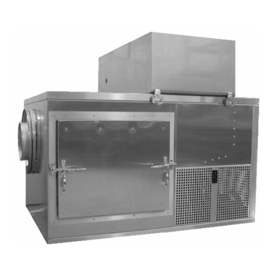
500-1000 CFM Air Handler
460V, 60 Hz
Model #9354-4250
(800) 438-5494 (828) 669-6928 FAX
.
.
.
Advertisement
Chapters
Table of Contents

Summary of Contents for Parameter Generation and Control 9354-4250
- Page 1 Parameter Generation and Control, Inc. Black Mountain, North Carolina (828) 669-8717 500-1000 CFM Air Handler 460V, 60 Hz Model #9354-4250 Installation and Operation Manual Customer Serial # Ship Date Parameter Generation and Control, Inc. P. O. Box 129 1054 Old US 70 West Black Mountain, NC 28711...
- Page 2 PGC Inc. Horizontal 500-1000 CFM June 2006 Parameter Generation and Control, Inc.
-
Page 3: Table Of Contents
Control Modes ......................12 Specifications, 500-1000 CFM ..................13 Replacement Parts, 500-1000 CFM................14 Appendices Appendix A – Technical Information Appendix B – SmartPad™ Operation Manual Appendix C – Diagrams Appendix D - Manuals for Accessory Equipment Parameter Generation and Control, Inc. -
Page 4: Inspection
6.6 (25) Process Water Inlet Connect a clean water supply line through an external customer-supplied hand valve to the Process Water Inlet connection on the rear of the conditioner; this is a ½” male NPT connection. Parameter Generation and Control, Inc. - Page 5 500-1000 CFM The following graph indicates the maximum coolant flow requirements for the condenser. 500-1000 CFM Maximum Condensor Water Flow Requirements 5.00 4.00 3.00 2.00 1.00 0.00 Entering Water Temperature (Degrees F) Parameter Generation and Control, Inc.
- Page 6 The water fill valve float may be padded to prevent damage during CAUTION shipping. Remove the padding before connecting the water supply to the inlet. The conditioner will not operate until the low water level safety is satisfied. NOTE Parameter Generation and Control, Inc.
- Page 7 PGC Inc. Horizontal 500-1000 CFM June 2006 CAUTION Do not connect the drain connection to an un-vented drain. Ensure that the drain connection is vented, as shown below. “Open” (Vented) Drain Connections Parameter Generation and Control, Inc.
-
Page 8: Electrical Connections
Exchanging phases at this point will reverse the rotation of all 3-phase motors. Parameter Generation and Control, Inc. -
Page 9: Operation
The SmartPad™ user interface is configured with a Standby key located in the lower right corner of the keypad. Pressing this key will disable the system and place the controller in a Standby mode. The SmartPad™ display will indicate: Parameter Generation and Control, Inc. -
Page 10: Process Variable Display
For instance, if the SmartPad™ was in Standby mode when power was lost, it will be in Standby mode when power is restored. If the SmartPad™ was operating and controlling the chamber, it will return to that mode of operation. Parameter Generation and Control, Inc. -
Page 11: Fault Displays
Some faults will clear automatically and others will require user intervention. NOTE Regardless of the fault clearing mechanism, the user must press the Standby in order for the conditioner to resume operation. Parameter Generation and Control, Inc. -
Page 12: Control Modes
Although this mode is accessible in SmartPad, it is non- functional unless the system is equipped with a desiccant dryer. Parameter Generation and Control, Inc. -
Page 13: Specifications, 500-1000 Cfm
Rh Constancy (control) ----------------------------------------------------------± 0.5% Minimum Rh is limited by a minimum dew point of 5°C (41°F) for standard Spray Mode. For example: Max. Rh Min. Rh Temperature 10°C (50°F) 25°C (77°F) 40°C (104°F) > 50°C (122°F) Parameter Generation and Control, Inc. -
Page 14: Replacement Parts, 500-1000 Cfm
HygroPalm Calibrator Rotronic HygroPalm 2 1609-0865 Latches, Access Panel Southco 62-43-251-3 1008-0080 Latches, Inner Doors Southco 1001-0082 Latches, Outer Doors McMaster-Carr 5481K19 1009-1017 Mist Eliminator 5000-0135 Motor Protector Siemens 3RV1021-1KA10 0427-1250 Motor Protector Siemens 3RV1021-0GA10 0427-0063 Parameter Generation and Control, Inc. - Page 15 Severn Trent Water 2450UD 0215-2824 UV Plastic Support 0215-2826 Valve, Expansion, Body Danfoss 068U2287 0215-0872 Valve, Expansion, Cartridge Danfoss 068U1037 0215-0777 Valve, Hot Gas Temp Control Sporlan SDR-3-20-S 0215-0873 Valve, Sump Float Hawkeye Steel UFV600 0209-0050 Products Parameter Generation and Control, Inc.
- Page 16 Parameter Generation and Control, Inc Precise Humidity Control Notes: ________________________________________________________________________ ________________________________________________________________________ ________________________________________________________________________ ________________________________________________________________________ ________________________________________________________________________ ________________________________________________________________________ ________________________________________________________________________ ________________________________________________________________________ ________________________________________________________________________ ________________________________________________________________________ ________________________________________________________________________ ________________________________________________________________________ ________________________________________________________________________ ________________________________________________________________________ ________________________________________________________________________ ________________________________________________________________________ ________________________________________________________________________ ________________________________________________________________________ ________________________________________________________________________ ________________________________________________________________________ www.humiditycontrol.com (800) 438-5494 sales@humiditycontrol.com Fax (828) 669-6928 (828) 669-8717 Black Mountain, North Carolina...
- Page 17 PGC, Inc 500-1000 CFM Air Handler May 2006 Appendix A System Construction ........................2 Theory of Operation........................3 Description of Operation......................4 Measurement of Test Chamber Conditions ................4 Air Flow..........................4 Water Flow ..........................5 Temperature Controls ......................5 Description of Circuitry ......................
-
Page 18: System Construction
PGC, Inc 500-1000 CFM Air Handler May 2006 YSTEM ONSTRUCTION The 500-1000 CFM Conditioner consists of four main sections: 1. Conditioning Compartment: spray bypass damper, blower, spray eliminators, spray jets, water sump, low water level safety float switch, process water float valve, stirring jet, evaporator coil, and particulate filter 2. -
Page 19: Theory Of Operation
PGC, Inc 500-1000 CFM Air Handler May 2006 HEORY OF PERATION PGC’s method of control is the same both reach-in chambers conditioning systems. The environment to be Supply Air conditioned is controlled at a targeted dew point temperature, and then reheated to the desired temperature. -
Page 20: Description Of Operation
PGC, Inc 500-1000 CFM Air Handler May 2006 ESCRIPTION OF PERATION The 500-1000 CFM Conditioner is a self-contained conditioner designed to control dry-bulb temperatures over a range of 7°C – 60°C (44.6ºF - 140ºF), dependent upon the size and construction of the test chamber. The dry-bulb temperature is held to ± 0.2°C and relative humidity constancy to ±... -
Page 21: Water Flow
PGC, Inc 500-1000 CFM Air Handler May 2006 In Slow Damper mode, the position of the damper is load dependent; the damper will change slowly to achieve the desired conditions. The damper will also change NOTE position in order to compensate for droop or overshoot in the air temperature control loop. - Page 22 PGC, Inc 500-1000 CFM Air Handler May 2006 Water Temperature Set Point Limits Minimum and maximum Water Set Point limits are factory pre-set in order to prevent freezing or overheating the pump. Dew Point Humidity is a function of air temperature and dew point, and the water temperature is directly related to dew point The controller limits the Water Set Point to 1ºC <...
-
Page 23: Description Of Circuitry
PGC, Inc 500-1000 CFM Air Handler May 2006 ESCRIPTION OF IRCUITRY Although this conditioner utilizes 24 volts DC for the control circuits, some components require 120 or 460VAC; these voltages can be present even when the CAUTION conditioner is not operating. Power to the unit should be removed at the wall disconnect prior to opening any of CAUTION the access panels. - Page 24 PGC, Inc 500-1000 CFM Air Handler May 2006 The position of the air bypass damper is determined by the PLC based on the air output percentage. The input to the damper actuator is a frequency modulated (FM) square-wave signal. The damper will be positioned based on the frequency of the FM signal. A yellow LED on the PLC indicates the duty cycle.
-
Page 25: Safety Devices
PGC, Inc 500-1000 CFM Air Handler May 2006 AFETY EVICES The unit is equipped with several safety devices to guard against serious trouble due to failure of any components. Alarm contacts are available on the PLC, which will switch when either of the process variables is in an alarm condition. - Page 26 PGC, Inc 500-1000 CFM Air Handler May 2006 High Pressure Reset Low Pressure Switch High Pressure Switch Air Temperature Figure A-2 - Pressure Switches Safety Thermostat Over Temperature Thermostat An air over-temperature safety thermostat has been incorporated into the chamber. The temperature adjustment for this device is located at the rear of the unit, on the side of the heater housing.
- Page 27 PGC, Inc 500-1000 CFM Air Handler May 2006 opens, the air handler will shut down. The SmartPad™ user interface will indicate “FAN TEMP FAULT SET”. The thermostat will automatically reset when the blower motor tempeature returns to a safe operating level. After the thermostat has reset, the SmartPad™ user interface will indicate “FAN TEMP FAULT CLEAR”, and the system may be restarted by pressing the Standby key on the SmartPad™...
-
Page 28: Troubleshooting
PGC, Inc 500-1000 CFM Air Handler May 2006 ROUBLESHOOTING CAUTION If the unit has a sight glass / moisture indicator, the hot gas bypass valve may cause a false indication of low refrigerant charge if the valve is not closed at the time it is being observed. -
Page 29: Air Temperature
PGC, Inc 500-1000 CFM Air Handler May 2006 ii. Is ice present on the fins of the evaporator (or on the surface of the submerged tube evaporator)? It is not unusual for the supply lines to the finned evaporator to be covered in ice; however, it is important that no ice form on the surface of the coil. -
Page 30: Rh Control
PGC, Inc 500-1000 CFM Air Handler May 2006 ONTROL The humidity cannot be controlled if the water temperature or air temperature is out of control; refer to the respective troubleshooting section. Verify that the air flow through the mist eliminator is unrestricted; restrictions could permit water droplets to bypass the mist eliminator. -
Page 31: Maintenance
PGC, Inc 500-1000 CFM Air Handler May 2006 AINTENANCE PGC chambers are designed to be reliable and require minimal maintenance. If the Conditioner is to be out of service for an extended period, it is advisable to clean the spray chamber interior to remove contaminants that collected;... - Page 32 PGC, Inc 500-1000 CFM Air Handler May 2006 and the water is replaced by the supply. Over time, the concentration of all these impurities increases and deposit out on the coils and other parts of the chamber. Periodic draining and flushing with clear water will significantly reduce such accumulations.
- Page 33 PGC, Inc 500-1000 CFM Air Handler May 2006 2. Remove the filter carrier by un-screwing it from the base.. 3. Remove the used filter using an “un-screwing” motion. 4. Install the new filter. Typically, the filter can simply be “pressed” into the housing. 5.
-
Page 34: Automatic Damper Motor Adjustments
PGC, Inc 500-1000 CFM Air Handler May 2006 11. Install the quartz tube o-ring, S/S retaining washer and the blue, aluminum gland nut. Do not over tighten the gland nut or the quartz tube will crack. 12. Install the new UV lamp and connect the wiring harness. The rubber boot on the wiring harness will secure the lamp in the quartz tube. -
Page 35: Calibration
PGC, Inc 500-1000 CFM Air Handler May 2006 ALIBRATION ALIBRATION The air temperature and Rh are measured by a self-contained and calibrated Rotronics HygroClip™ T/Rh transmitter. The Rotronics HygroClip™ T/Rh transmitter should be recalibrated annually. The three different options for calibration are Exchange, Calibration in an Independent Chamber, and Calibration In Place Exchange Both PGC and Rotronics©... - Page 36 PGC, Inc 500-1000 CFM Air Handler May 2006 “Piggy-back” HygroPalm™ Connection Calibration header HygroPalm™ Connection Figure A-13 – ACE4 PCB, HygroPalm™ Connection If the HygroClip™ is located more than 5 meters from the air handler, it will require an amplifier on the digital signal.
- Page 37 PGC, Inc 500-1000 CFM Air Handler May 2006 HygroPalm© Single-Point Temperature Calibration Procedure Install a temperature reference as close as possible to the HygroClip© sensor. Using a special cable from PGC (Part Number 1609-866), connect the HygroPalm© to ACE pc board at the two-pin connector in the upper left-hand corner, labeled DIO. It is important to note that as long as the HygroPalm©...
-
Page 38: Water Temperature Calibration
PGC, Inc 500-1000 CFM Air Handler May 2006 ATER EMPERATURE ALIBRATION The water RTD (RTD1) can be calibrated via the user interface. This sensor was calibrated prior to shipment and typically will not require re-calibration. However, if calibration is necessary refer to the SmartPad™... - Page 39 PGC, Inc 500-1000 CFM Air Handler May 2006 Water RTD Calibration Procedure with Precision Resistors: 1.) Zero Offset, or Single Point Offset. a. Place the low temperature precision resistor in the RTD circuit. b. Access the RTD calibration screens in the SmartPad™: •...
- Page 40 Parameter Generation and Control, Inc Precise Humidity Control Notes: ________________________________________________________________________ ________________________________________________________________________ ________________________________________________________________________ ________________________________________________________________________ ________________________________________________________________________ ________________________________________________________________________ ________________________________________________________________________ ________________________________________________________________________ ________________________________________________________________________ ________________________________________________________________________ ________________________________________________________________________ ________________________________________________________________________ ________________________________________________________________________ ________________________________________________________________________ ________________________________________________________________________ ________________________________________________________________________ ________________________________________________________________________ ________________________________________________________________________ ________________________________________________________________________ ________________________________________________________________________ www.humiditycontrol.com (800) 438-5494 sales@humiditycontrol.com Fax (828) 669-6928 (828) 669-8717 Black Mountain, North Carolina...
- Page 41 Parameter Generation and Control, Inc. Black Mountain, North Carolina (828) 669-8717 SmartPad™ Operation Manual Steady State and Programmable Set Point Entry Mode Software Version 0.503 November, 2005...
- Page 42 PGC, Inc. Appendix B; SmartPad version 0.503 Steady State & Programmable November 2005...
- Page 43 PGC, Inc. Appendix B; SmartPad version 0.503 Steady State & Programmable PGC SmartPad™ CONTROL SYSTEM version 0.503 The SmartPad™ control system consists of a user interface and a unit control module. The user interface is the SmartPad™ and the control module is located in the electrical compartment of the machine. The SmartPad™ will be accessible to the user.
-
Page 44: Smartpad™ User Interface
PGC, Inc. Appendix B; SmartPad version 0.503 Steady State & Programmable SmartPad™ USER INTERFACE The SmartPad™ was initially shipped with an access code of 0000. If the code has been changed and lost, please contact PGC for assistance. The SmartPad™ may be configured in a steady state or 60 segment programmable controller set point entry mode as desired. - Page 45 PGC, Inc. Appendix B; SmartPad version 0.503 Steady State & Programmable The SmartPad™ control interface is designed to be as user friendly as possible. The basic purpose of the control system is to provide a display with various screens used for entering the desired operating conditions for the conditioner, as well as to display the actual conditions measured by the sensors.
-
Page 46: Process Variable Screen (Steady State Mode
PGC, Inc. Appendix B; SmartPad version 0.503 Steady State & Programmable Process Variable Screen (Steady State Mode) The process variable screen displays the measured air temperature and relative humidity or water temperature (depending on the operating mode chosen). Depressing the ESC function key on any screen will access the process variable screen. AIR or RH/H2O ACTUAL indicates the current measured conditions in the chamber. -
Page 47: Output Screen (Steady State And Programmable Modes
PGC, Inc. Appendix B; SmartPad version 0.503 Steady State & Programmable Output Screen (Steady State and Programmable Modes) The output screen indicates the position of the air bypass damper, dryer bypass damper and the power applied to the air and water heaters. These outputs can be in the range of 0.00% (full cooling) to 100.0% (full heating). -
Page 48: Preferences Screen (Steady State And Prog Modes
PGC, Inc. Appendix B; SmartPad version 0.503 Steady State & Programmable Preferences Screen (Steady State and Prog Modes) The access screen allows the user to enter a four-digit password to gain access to the customer configuration and factory configuration screens. The user can configure the password to any four digits they choose except for 7178. -
Page 49: Program Set Point Screen (Programmable Mode
PGC, Inc. Appendix B; SmartPad version 0.503 Steady State & Programmable Program Set Point Screen (Programmable Mode) The program set point screen allows the user to enter the program data. Up to 40 segments can be entered (00-39). Each segment must include a duration time as well as the two set point parameters (Air/Rh in cascade, dryer or slow damper mode or Air/Water in two temperature mode). -
Page 50: Initilization Screen (Programmable Modes
PGC, Inc. Appendix B; SmartPad version 0.503 Steady State & Programmable Initilization Screen (Programmable Modes) The initialization screen allows the user to specify the loop parameters for the ramp and soak profile. START AT SEG indicates the initial segment in the profile. LOOP FROM SEG indicates the final segment in the profile. -
Page 51: Mode Configuration Screen (Programmable Modes
PGC, Inc. Appendix B; SmartPad version 0.503 Steady State & Programmable Mode Configuration Screen (Programmable Modes) The mode configuration screen allows the user to enable certain features and automatically change operating modes. PROGRAM CHANGE: indicates the data that can be programmed (two characters). SEG: indicates the segment to be programmed. - Page 52 PGC, Inc. Appendix B; SmartPad version 0.503 Steady State & Programmable Right Nibble Definition Data Reconfigure Mode NO ACTION NO ACTION NO ACTION NO ACTION CASCADE MODE TWO TEMPERATURE MODE DRY MODE SLOW DAMPER MODE NO ACTION NO ACTION Programming examples: PRGC = 00 All digital outputs are off.
-
Page 53: Monitor Water Values Screen (Steady State And Prog Modes
PGC, Inc. Appendix B; SmartPad version 0.503 Steady State & Programmable Monitor Water Values Screen (Steady State and Prog Modes) The monitor water values screen allows the user to observe the measured water temperature and the water set point that is determined by the cascade control loop. These values cannot be modified. -
Page 54: More Screens (Steady State And Prog Modes
PGC, Inc. Appendix B; SmartPad version 0.503 Steady State & Programmable More Screens ( Steady State and Prog Modes) The more screen provides access to the alarm condition screen and the preference screen. This screen will also display the serial number of the system, the SmartPad software version number and the current operating mode. -
Page 55: Alarm Condition Screen (Steady State And Prog Modes
PGC, Inc. Appendix B; SmartPad version 0.503 Steady State & Programmable Alarm Condition Screen (Steady State and Prog Modes) The alarm condition screen indicates the status of all alarms in the system. Line two will indicate the current alarm or no alarm if the system is not in an alarm condition. If multiple alarms occur only the first alarm will be displayed. -
Page 56: Access Code Screen (Steady State And Prog Modes
PGC, Inc. Appendix B; SmartPad version 0.503 Steady State & Programmable Access Code Screen (Steady State and Prog Modes) The access code screen is accessed from the area modification screen by choosing CODE. Entering a four-digit number will change the access code to the value entered. Pressing DONE will access the current access code screen to display the access code. -
Page 57: Water Rtd Zero Calibration Screen
PGC, Inc. Appendix B; SmartPad version 0.503 Steady State & Programmable Water RTD ZERO Calibration Screen (Steady State and Prog Modes) The first step in calibrating the water RTD is to set the zero or offset value. This value should be as close as practical to the minimum operating temperature. -
Page 58: Aux Rtd Calibration Screen
PGC, Inc. Appendix B; SmartPad version 0.503 Steady State & Programmable Aux RTD Calibration Screen (Steady State and Prog Modes) A second RTD can be accessed for calibration from the SmartPad. This is an optional sensor that may not be present on every system. (Note that when the controller is configured for reactivation control in dry mode, this RTD will be the reactivation temperature sensor). - Page 59 PGC, Inc. Appendix B; SmartPad version 0.503 Steady State & Programmable After the auxiliary RTD zero adjustment it is necessary to adjust the span or scaling factor for the input. This adjustment will determine the slope of the calibration curve. This value should be as close as practical to the maximum operating temperature.
-
Page 60: Factory Configuration Menu (Steady State And Prog Modes
PGC, Inc. Appendix B; SmartPad version 0.503 Steady State & Programmable Factory Configuration Menu (Steady State and Prog Modes) Entering 7178 in the access code field will display the factory configuration menu. This menu will allow the user to re-configure the SmartPad™ for various operating modes and/or set point entry options. -
Page 61: Alarm Control Menu (Steady State And Prog Modes
PGC, Inc. Appendix B; SmartPad version 0.503 Steady State & Programmable Alarm Control Menu (Steady State and Prog Modes) Pressing ALRM in the area modification screen will access the alarm control menu. Inside this menu the user can step through a list of values that can be modified using the PREV (F1) and NEXT (F2) keys. -
Page 62: Tuning Control Menu (Steady State And Prog Modes
PGC, Inc. Appendix B; SmartPad version 0.503 Steady State & Programmable Tuning Control Menu (Steady State and Prog Modes) Pressing TUNE in the area modification screen will access the tuning control menu. Inside this menu the user can step through a list of values that can be modified using the PREV (F1) and NEXT (F2) keys. The top line of the display will indicate the current operating mode. - Page 63 PGC, Inc. Appendix B; SmartPad version 0.503 Steady State & Programmable RH CASCADE CONTROL 00.00 to 99.99 (varies with Defines the minimum water H2O Low Limit hardware) temperature set point that the system will allow. This value is hardware specific, but is usually set to prevent freezing.
-
Page 64: Set Point Entry (Steady State Mode
PGC, Inc. Appendix B; SmartPad version 0.503 Steady State & Programmable SET POINT ENTRY (Steady State Mode) The SmartPad™ has been designed to be as user-friendly as possible. To enter the desired set point for the chamber, press the “SP” key to enter the Set Point Screen. This can be done from the Process Variable Screen. -
Page 65: Set Point Entry (Programmable Mode
PGC, Inc. Appendix B; SmartPad version 0.503 Steady State & Programmable SET POINT ENTRY (Programmable Mode) The following sample program covers many of the different types of segments typically used. NOTE - Although segment 00 is functionally equivalent to the other segments, it should generally be avoided as the first segment in the program. -
Page 66: Actual Loading Of The Program
PGC, Inc. Appendix B; SmartPad version 0.503 Steady State & Programmable SEGMENT 07: We now wish to ramp back down to our original conditions of 25 deg. C and 45% RH in 40 minutes. TIME AIR SET POINT RH SET POINT 00 00 01 25.0 45.0... -
Page 67: Verifying The Program
PGC, Inc. Appendix B; SmartPad version 0.503 Steady State & Programmable the display should have moved all the way through the temperature indication and back to the beginning. If it is entered as desired, depress the "TAB" key. The first digit of the "RH set point" should be flashing. On the number pad depress 450. It is not necessary to enter the decimal point. -
Page 68: Additional Programming Information
PGC, Inc. Appendix B; SmartPad version 0.503 Steady State & Programmable ADDITIONAL PROGRAMMING INFORMATION If you enter 00 00 00 for time in any segment, the SmartPad™ will stop at, but not perform that segment. The time display will stop counting down, this is the indication that the SmartPad™... -
Page 69: Pgc Smartpad™ Serial Communications
PGC, Inc. Appendix B; SmartPad version 0.503 Steady State & Programmable PGC SmartPad™ Serial Communications The SmartPad™ is capable of communication with a remote terminal via RS-232 protocol. The connection is made at a DB-9 male connector on the cabinet. I. -
Page 70: Iv. Types Of Commands
PGC, Inc. Appendix B; SmartPad version 0.503 Steady State & Programmable IV. TYPES OF COMMANDS: The SmartPad™ will respond to two types of commands; requests and inputs. A request is a command that instructs the SmartPad™ to return a value to the terminal. An example of this is if the terminal were to request the current measured air temperature. - Page 71 PGC, Inc. Appendix B; SmartPad version 0.503 Steady State & Programmable V. COMMANDS: REQUEST COMMANDS: Command Function ?OO<CR> Returns current run state (On/Off request) ?CM<CR> Returns current Control Mode (Rh Cascade, Two Temp, etc.) ?SM<CR> Returns current Set point entry Mode ?AP<CR>...
-
Page 72: Input Commands
PGC, Inc. Appendix B; SmartPad version 0.503 Steady State & Programmable INPUT COMMANDS: (Note: Sign byte is optional on inputs. Set point input commands may only be used in steady state modes) Command Function =OO<CR> Toggles current run state (On/Off command) =RC<CR>... - Page 73 PGC, Inc. Appendix B; SmartPad version 0.503 Steady State & Programmable TROUBLESHOOTING: There are many possible hurdles that can prevent valid data transfer from the SmartPad™ to a remote terminal and vice-versa. Here is a partial discussion of potential problems and a recommended correction for the problem: When the SmartPad™...
- Page 74 STEADY STATE, TWO TEMPERATURE MODE METER SCREEN PROGRESSION CHART VER 503 AIR ACTUAL 25.0°C H2O ACTUAL 10.0°C MORE MORE PERCENTAGE OUTPUT SET POINT AIR HEAT OUT 50.0% SmartPad SN: 1234567 AIR SETPOINT 25.0°C H2O HEAT OUT 50.0% Software ver. 501f H20 SETPOINT 10.0°C STEADY STATE TWOTEMP PREF...
- Page 75 STEADY STATE, CASCADE MODE METER SCREEN PROGRESSION CHART VER 503 AIR ACTUAL 25.0°C ACTUAL 50.0 % MORE PERCENTAGE OUTPUT MORE MONITOR SET POINT AIR SETPOINT 25.0°C AIR HEAT OUT 50.0% SmartPad SN: 1234567 SETPOINT 50.0 % H2O HEAT OUT 50.0% Software ver.
- Page 76 STEADY STATE, DRYER MODE METER SCREEN PROGRESSION CHART VER .503 AIR ACTUAL 25.0°C ACTUAL 50.0 % MORE PERCENTAGE OUTPUT MORE MONITOR SET POINT AIR SETPOINT 25.0°C AIR HEAT OUT 50.0% SmartPad SN: 1234567 SETPOINT 50.0 % DRYER OUT 50.0% Software ver. 501f STEADY STATE DRYER PREF...
- Page 77 STEADY STATE, SLOW DAMPER CASCADE MODE METER SCREEN PROGRESSION CHART VER 503 AIR ACTUAL 25.0°C ACTUAL 50.0 % MORE PERCENTAGE OUTPUT MORE MONITOR SET POINT AIR SETPOINT 25.0°C AIR HEAT OUT 50.0% SmartPad SN: 1234567 SETPOINT 50.0 % H2O HEAT OUT 50.0% Software ver.
- Page 78 METER PROGRAMMABLE, TWO TEMPERATURE MODE SCREEN PROGRESSION CHART VER 503 AIR ACTUAL 23.0°C H2O ACTUAL 15.0°C SEG 19 TIME 17:59:59 HALT PROG MORE MONITOR SET POINT MORE PROGRAM SEG 19 TIME 17:59;59 SmartPad SN: 1234567 SEG 19 TIME 17:59:59 AIR SETPOINT 23.0°C Software ver.
- Page 79 PROGRAMMABLE, CASCADE MODE METER SCREEN PROGRESSION CHART VER 503 AIR ACTUAL 23.0°C ACTUAL 50.0 % SEG 19 TIME 17:59:59 HALT PROG MORE MONITOR SET POINT MORE PROGRAM SEG 19 TIME 17:59;59 SmartPad SN: 1234567 SEG 19 TIME 17:59:59 AIR SETPOINT 23.0°C Software ver.
- Page 80 METER PROGRAMMABLE, DRYER MODE SCREEN PROGRESSION CHART VER .503 AIR ACTUAL 23.0°C ACTUAL 50.0 % SEG 19 TIME 17:59:59 HALT PROG MORE MONITOR SET POINT MORE PROGRAM SEG 19 TIME 17:59;59 SmartPad SN: 1234567 SEG 19 TIME 17:59:59 AIR SETPOINT 23.0°C Software ver.
- Page 81 METER PROGRAMMABLE, SLOW DAMPER CASCADE MODE SCREEN PROGRESSION CHART VER 503 AIR ACTUAL 23.0°C ACTUAL 50.0 % SEG 19 TIME 17:59:59 HALT PROG MORE MONITOR SET POINT MORE PROGRAM SEG 19 TIME 17:59;59 SmartPad SN: 1234567 SEG 19 TIME 17:59:59 AIR SETPOINT 23.0°C Software ver.
- Page 82 Parameter Generation and Control, Inc Precise Humidity Control Notes: ________________________________________________________________________ ________________________________________________________________________ ________________________________________________________________________ ________________________________________________________________________ ________________________________________________________________________ ________________________________________________________________________ ________________________________________________________________________ ________________________________________________________________________ ________________________________________________________________________ ________________________________________________________________________ ________________________________________________________________________ ________________________________________________________________________ ________________________________________________________________________ ________________________________________________________________________ ________________________________________________________________________ ________________________________________________________________________ ________________________________________________________________________ ________________________________________________________________________ ________________________________________________________________________ ________________________________________________________________________ www.humiditycontrol.com (800) 438-5494 sales@humiditycontrol.com Fax (828) 669-6928 (828) 669-8717 Black Mountain, North Carolina...
Need help?
Do you have a question about the 9354-4250 and is the answer not in the manual?
Questions and answers