Table of Contents
Advertisement
Quick Links
S
V
ENTINEL
S
V
ENTINEL
O
M
PERATION
ANUAL
Information included herein is controlled by the Export Administration Regulations (EAR) and may
require an export license, license exception or other approval from the appropriate U.S. Government
agency before being exported from the United States or provided to any foreign person. Diversion
contrary to U.S. law is prohibited.
S
-C
ELF
ONTAINED
R
-T
EAL
IME
P/N 95D-6002-00 (September 2017)
© 2017 Teledyne RD Instruments, Inc. All rights reserved.
Advertisement
Table of Contents
Troubleshooting

Related Manuals for Teledyne RD Instruments SENTINEL V SELF-CONTAINED


Summary of Contents for Teledyne RD Instruments SENTINEL V SELF-CONTAINED
- Page 1 ANUAL P/N 95D-6002-00 (September 2017) © 2017 Teledyne RD Instruments, Inc. All rights reserved. Information included herein is controlled by the Export Administration Regulations (EAR) and may require an export license, license exception or other approval from the appropriate U.S. Government agency before being exported from the United States or provided to any foreign person.
- Page 2 Page ii EAR-Controlled Technology Subject to Restrictions Contained on the Cover Page.
-
Page 3: Table Of Contents
......................39 HAPTER WITCHING ODES Switching RT and SC Modes ......................... 39 Switching to the Sentinel V Real-Time Mode ..................40 Switching to the Sentinel V Self-Contained Mode ................41 2 – U V ..........................43 HAPTER SING EADY ReadyV Interface Features ........................... 44 Using the Home Panel .......................... - Page 4 Error Messages ............................. 54 Step 1: Scenario ............................ 54 Step 2: Settings............................. 55 Using Real-Time Serial Data Output ......................55 Serial Port Application Notes ....................... 57 Step 3: Profiling ............................ 59 Using the Review System Panel ........................61 Sensor Data ............................62 Activating and Deactivating Features ....................
- Page 5 Restore to Factory Defaults ........................119 Periodic Maintenance ..........................120 Running the Built-in Tests ........................121 Testing the Sentinel V Self-Contained .................... 121 Testing the Sentinel V Real-Time ....................121 Setting the Date and Time ........................122 Setting the Date and Time on Self-Contained Systems ..............122 Setting the Date and Time on Real-Time Systems .................
- Page 6 Standard Sensor Commands ........................ 192 AZ – Zero Pressure Sensor ......................192 Bottom Track Commands ..........................193 Available Bottom Track Commands ..................... 193 BA - Evaluation Amplitude Minimum ..................... 194 BC - Correlation Magnitude Minimum ................... 194 BE - Error Velocity Maximum ......................194 BF - Manual Fixed Altitude ......................
- Page 7 FD – Display Fault Log ........................221 Performance and Testing Commands ......................222 Available Performance and Testing Commands ................... 222 Performance and Testing Command Descriptions ................222 PA – Run Go/No-Go Tests ......................222 PC – User Interactive Built-In Tests ....................223 PD –...
- Page 8 Header Data Format ..........................249 Fixed Leader Data Format ........................251 Variable Leader Data Format ....................... 256 Velocity Data Format..........................261 Correlation Magnitude, Echo Intensity, and Percent-Good Data Format ..........263 Transformation Matrix Format ......................266 Sentinel V Specific Structures ....................... 268 Sentinel V System Configuration ....................
- Page 9 73D-3101 – External Battery Case Cable with 8-pin Connector ..........82 Figure 35. Connecting the External Battery Case ..................83 Figure 36. Example of a Teledyne RD Instruments PVC Bottom Mount ........... 84 Figure 37. Example of a Bottom Mounted ADCP ..................84 Figure 38.
- Page 10 Figure 71. Power I/O Cable Connection ....................141 Figure 72. 96D-6000 Sheet 1 ........................158 Figure 73. 96D-6000 Sheet 2 ........................159 Figure 74. 96D-6000 Sheet 3 ........................160 Figure 75. 96D-6000 Sheet 4 ........................161 Figure 76. 96D-6000 Sheet 5 ........................162 Figure 77.
- Page 11 Table 3. Blank Distance, Range, and Cell Size ..................60 Table 4. Underneath Vessel Mounting of a Sentinel V20/V50 ADCP ............. 90 Table 5. Underneath Vessel Mounting of a Sentinel V100 ADCP ............91 Table 6. Tools and Spares Parts ......................97 Table 7.
- Page 12 ANUAL EVISION ISTORY September 2017 • Added Using Sentinel V RT Utilities software • Added Ethernet communications • Added using *.feature files for upgrades • Added Using the Trigger • Added troubleshooting Ethernet communications • Updated specifications • Added Sea Chest to Installation chapter •...
- Page 13 • Updated Supported Operating Systems and Browsers. • Updated Chapter 2 to show new ReadyV screens. • Removed ReadyVLite chapter. • Updated compass calibration procedures to show new ReadyV screens. • Updated the specifications. March 2015 • Added note to not have 50 or more data files on the recorder when deploying. •...
- Page 14 • Updated the compass calibration procedure in chapter 5. July 2013 • Added a Compass Calibration Guide and updated the compass calibration procedure. • Changed input power from +9 to 24VDC to +12 to 20VDC. • Updated graphics to show longer housing. •...
- Page 15 XCLUSIONS AND MISSIONS • ReadyV does not have any native support for Windows 8® Internet Explorer 10 Metro Browser. Any ReadyV requests made through the Metro browser is forwarded to the Windows 8 Internet Explorer 10 Desktop browser. • Users may need to turn off their browser pop-up blockers (either built-in or third party) in order to access ReadyV.
- Page 16 ONTACTING If you have technical issues or questions involving a specific application or deployment with the instru- ment, contact our Field Service group: Teledyne RD Instruments Teledyne RD Instruments Europe 14020 Stowe Drive 2A Les Nertieres Poway, California 92064 5 Avenue Hector Pintus...
-
Page 17: Chapter 1 - Self -Contained
Sentinel V SC and RT Operation Manual September 2017 Chapter ONTAINED ENTINEL VERVIEW In this chapter, you will learn: • Sentinel V ADCP features • What options are available? • What type of computer do I need? • What are the ADCP power requirements? •... -
Page 18: Sentinel V Features
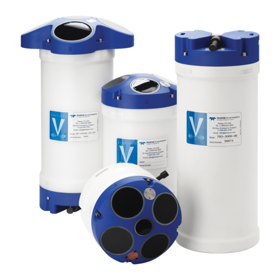
September 2017 Sentinel V SC and RT Operation Manual Sentinel V Features The Sentinel V is designed for several-month autonomous current profile deployment from temporary or permanent mounting in the ocean, near-shore, harbors, and lakes. The Sentinel V Series ADCP consists of an ADCP, battery pack or individual D cell batteries, microSDHC memory card, and software. -
Page 19: Figure 2. Sentinel V20 With D Cell Batteries And Optional End-Cap Call Out Beam Numbers
Sentinel V SC and RT Operation Manual September 2017 Figure 2. Sentinel V20 with D Cell Batteries and Optional End-Cap call out beam numbers Page 3 EAR-Controlled Technology Subject to Restrictions Contained on the Cover Page. -
Page 20: Figure 3. External Battery Case Overview
September 2017 Sentinel V SC and RT Operation Manual Figure 3. External Battery Case Overview The External Battery Case holds two battery packs that are shipped inside the case but not connected. Connect BOTH batteries and seal the external battery case before deployment. is necessary to remove the top battery in order to connect the bottom battery cable. -
Page 21: Available Options
Sentinel V SC and RT Operation Manual September 2017 Available Options The following section explains the different options available for Sentinel V Series ADCPs. See the Parts Location Drawings for more information. • Transducer – The standard nominal ranges are 20m (1000 kHz), 50m (500 kHz) and 100m (300 kHz). -
Page 22: System Inventory
Included with the Sentinel V system: Part Number Name Description Sentinel V SC or RT Sentinel V Self-Contained (SC) or Real-Time (RT) ADCP. Depending on housing type: ADCP with • Sentinel V battery packs are shipped inside the system but not connected. S100 transducer cover •... -
Page 23: Computer Considerations
Sentinel V SC and RT Operation Manual September 2017 Computer Considerations TRDI designed the Sentinel V Series Self-Contained ADCP to use a Windows® compatible computer. The built-in ReadyV user interface configures the ADCP and data is displayed through TRDI’s Velocity pro- gram. -
Page 24: Power Considerations
September 2017 Sentinel V SC and RT Operation Manual Power Considerations Use the following section to determine the power requirements for the Sentinel V Self-Contained ADCPs. • The Sentinel V system uses +18 VDC to operate. • Depending on the type of housing the system is configured with, the ADCP may use a battery pack, lithium battery pack (optional), individual D cell batteries, or external power. -
Page 25: Touch Sensor Response / System Beeps
Switching Modes. The Sentinel V Self-Contained ADCP includes an 802.11b/g/n WLAN interface and a built-in user inter- face called ReadyV. The Sentinel V Series ADCP acts as the server, along with the connected computer (laptop, tablet, or desktop computer) known as the client. -
Page 26: Using The Wireless Connection
September 2017 Sentinel V SC and RT Operation Manual Using the Wireless Connection To connect to the ADCP: 1. Prepare the ADCP by connecting the battery. After power is applied (long beep), there is a 10 to 15 second delay before the network is available (short beep). The WLAN is available after power up for two minutes. -
Page 27: Touch Sensor
Sentinel V SC and RT Operation Manual September 2017 Touch Sensor To use the touch sensor: 1. Place a finger over the Touch Sensor. This starts the ADCP’s WLAN for five minutes. After power is applied (long beep), there is a 10 to 15 second delay before the network is available (short beep). Wait for the short beep. -
Page 28: Start Readyv
September 2017 Sentinel V SC and RT Operation Manual Start ReadyV To start ReadyV: 1. Open a browser on the laptop (Internet Explorer , FireFox , Google Chrome , or other browser). ® ® ® 2. Enter the ADCP’s IP address 192.168.0.2 into the address bar. Optionally, on a Windows® based browser use the WLAN address http://SVnnnnn.adcp (where nnnnn is the five or six-char- acter Sentinel V serial number shown on the product label). -
Page 29: Figure 4. Using The Readyv Wireless Connection
Sentinel V SC and RT Operation Manual September 2017 Figure 4. Using the ReadyV Wireless Connection The Touch Sensor is NOT a button! Just place a finger into the cavity to activate the sensor. After power is applied (long beep), there is a 10 to 15 second delay before the network is available (short beep). -
Page 30: Connecting To Another Adcp
September 2017 Sentinel V SC and RT Operation Manual Connecting to another ADCP To connect to another ADCP: 1. Click on the wireless access-point icon ( ) in the Windows® system tray and select the ADCP on the list that is connected. 2. -
Page 31: Restoring A Readyv Lost Connection
Sentinel V SC and RT Operation Manual September 2017 Restoring a ReadyV Lost Connection Once ReadyV starts, if no keys are pressed for five minutes, the ADCP will disconnect. After waiting five more minutes, the ADCP will power down. Once the ADCP powers down, the wireless connection is lost. To reconnect: 1. -
Page 32: Wireless Connection Common Issues
September 2017 Sentinel V SC and RT Operation Manual Wireless Connection Common Issues The ADCP does not appear on the list of devices: The ADCP may have timed out. Place a finger over the Touch Sensor again. There is a short beep indicating that the WLAN is enabled on the ADCP. The ADCP’s WLAN will remain on for five minutes after the short beep. - Page 33 Sentinel V SC and RT Operation Manual September 2017 The ADCP is connected, but ReadyV does not start: Windows 7 may indicate it is connected and the signal strength is excellent even if the wireless connection is lost due to the ADCP going to sleep. Click on the wireless access-point icon ( ) in the Windows®...
- Page 34 September 2017 Sentinel V SC and RT Operation Manual When the browser is opened, there is a page not found error: Make sure the IP address 192.168.0.2 is typed in correctly. If you are using a Windows ® browser, try using the ADCP’s WLAN address http://SVnnnnn.adcp into the address bar (where nnnnn is the five or six-character Sentinel V serial number).
- Page 35 Sentinel V SC and RT Operation Manual September 2017 The connection was lost: Once ReadyV starts, if no keys are pressed for five minutes, the ADCP will discon- nect. After waiting five more minutes, the ADCP will power down. First close the internet browser page or the browser tab which was running ReadyV and then use the Touch sensor to restart.
- Page 36 September 2017 Sentinel V SC and RT Operation Manual OTES Page 20 EAR-Controlled Technology Subject to Restrictions Contained on the Cover Page.
-
Page 37: Time Sentinel V Overview
Sentinel V SC and RT Operation Manual September 2017 Chapter ENTINEL VERVIEW In this chapter, you will learn: • Sentinel V Real-Time ADCP features • Health & Environment Monitoring Sensors • Comparing Self-Contained & Real-Time • What type of computer do I need? •... -
Page 38: Sentinel V Real-Time Features
September 2017 Sentinel V SC and RT Operation Manual Sentinel V Real-Time Features Sentinel V Real-Time ADCP is designed for real-time applications such as vessel-mount, waves, and tur- bulence. It is a direct-read capable ADCP based on the Sentinel V hardware. It can be sold as a new unit, or as a field-upgradeable “kit”. -
Page 39: Available Real-Time Options
Sentinel V SC and RT Operation Manual September 2017 Available Real-Time Options The following section explains the different options available for RT ADCPs. See the Parts Location Draw- ings for more information. • Transducer – The standard nominal ranges are 20m (1000 kHz), 50m (500 kHz) and 100m (300 kHz). -
Page 40: Health & Environment Monitoring Sensors
September 2017 Sentinel V SC and RT Operation Manual Health & Environment Monitoring Sensors The Health and Environment Monitoring (HEM) Sensors monitor the health of the Sentinel V Real-Time system. • – The Sentinel V Real-Time system records the total time of operation in Operating Time minutes where “operation”... -
Page 41: Comparing Self-Contained & Real-Time
The V Series ADCP can be converted to a Sentinel V Real-Time and vice versa by changing the firmware (see Switching RT and SC Modes). Sentinel V Self-Contained Sentinel V Real-Time Real-Time currents, Continuous Waves, Intended Applications Self-Contained currents, Waves (Burst) -
Page 42: Real-Time System Inventory
Included with the Sentinel V system: Part Number Name Description Sentinel V SC or RT Sentinel V Self-Contained (SC) or Real-Time (RT) ADCP. Depending on housing type: ADCP with • Sentinel V battery packs are shipped inside the system but not connected. S100 transducer cover •... -
Page 43: Real-Time Software Overview
Sentinel V SC and RT Operation Manual September 2017 Real-Time Software Overview Sentinel V Real-Time Software: Command & Data Data Con- Testing Planning Compass Cal Display Post Process Control Acquisition vert Sentinel V Sentinel V VmDas VmDas VmDas VmDas Velocity VmDas Utilities Utilities... -
Page 44: Real-Time Computer Considerations
September 2017 Sentinel V SC and RT Operation Manual Real-Time Computer Considerations TRDI designed the Sentinel V Real-Time Series ADCP to use a Windows® compatible computer. Use Sen- tinel V RT Utilities to configure the ADCP; data is displayed through TRDI’s Velocity program. Minimum Computer Hardware Requirements: •... -
Page 45: Real-Time Power Considerations
Sentinel V SC and RT Operation Manual September 2017 Real-Time Power Considerations Use the following section to determine the power requirements for the Sentinel V Real-Time ADCPs. • The Sentinel V Real-Time uses external power through the end-cap connector. The voltage must be +12 to 20 VDC. -
Page 46: Real-Time Touch Sensor Response / System Beeps
September 2017 Sentinel V SC and RT Operation Manual Power on Cycle The power supply or battery pack must be able to handle the inrush current as well. Inrush current is the current required to fully charge up the capacitors when power is applied to the Sentinel V Series ADCP. The capacitors provide a store of energy for use during transmit. -
Page 47: Connecting To The Sentinel V Real-Time
Sentinel V SC and RT Operation Manual September 2017 Connecting to the Sentinel V Real-Time This applies to systems configured for Real-Time mode. See Switching RT and SC Modes. The Sentinel V Real-Time ADCP includes an external serial RS-232 or RS-422 cable connector on the end- cap. -
Page 48: Using Sentinel V Rt Utilities
September 2017 Sentinel V SC and RT Operation Manual Using Sentinel V RT Utilities To connect to the Sentinel V Real-Time ADCP using the Sentinel V RT Utilities software: 1. Select New Serial Connection or New Ethernet Connection. 2. Enter the ADCP’s communication settings. Serial Communications: Select the COM Port and Baud Rate from the drop down lists. -
Page 49: Using Ethernet Communications
Sentinel V SC and RT Operation Manual September 2017 Using Ethernet Communications Sentinel V Real-Time systems, starting in May 2017 supports Ethernet output. These systems must be fac- tory configured or field upgraded. Ethernet systems can be identified by the model number, such as S20-53PEWR-16G-200, where E stands for Ethernet. -
Page 50: Using Udp Broadcast Output
September 2017 Sentinel V SC and RT Operation Manual Using UDP broadcast Output For network directed UDP broadcast output, the following parameters are required: • Network directed UDP broadcast port With Broadcast (Auto) output, multiple remote machines that are listening on the same transmit UDP port will receive the same data. - Page 51 Sentinel V SC and RT Operation Manual September 2017 To install a firmware upgrade using a Sentinel V RT Utilities serial connection: 1. Connect to the Sentinel V Real-Time ADCP using Sentinel V RT Utilities and a serial port. 2. On the Wireless Status box, click the Turn On button. Wait for the second short beep before continuing.
-
Page 52: Downloading Sentinel V Real-Time Log Files
September 2017 Sentinel V SC and RT Operation Manual 8. Select Firmware Update and then click on Choose File to select the Sentinel V firmware bi- nary (sv_66.xx.xx.xx.xx.bin). Click the Update button. Figure 8. Sentinel V RT Utilities Page It takes several minutes to load the new firmware and the Sentinel-V Utilities screen may be blank during the update process. -
Page 53: Installing Feature Upgrades
Sentinel V SC and RT Operation Manual September 2017 Installing Feature Upgrades The feature upgrade installation program is used to install Waves and Bottom Track capabilities in a Sen- tinel V Real-Time system. Feature upgrades can be sent via a Sentinel V RT Utilities *.feature file. Features can only be activated or deactivated when connected to the ADCP and require a Feature file (*.feature) that is tied to the ADCP’s serial number. -
Page 54: Using The Trigger
September 2017 Sentinel V SC and RT Operation Manual Using the Trigger The Sentinel V Real-time has the ability to be triggered or to send triggers in order to synchronize pings or ensembles to external signals. Only the RS-232 configuration has wiring to allow both Trigger-in and Trigger-out. -
Page 55: Chapter 1 C - Switching Rt And Sc Modes
In this chapter, you will learn: • Switch to the Sentinel V Real-Time mode • Switch to the Sentinel V Self-Contained mode Switching RT and SC Modes The V Series Self-Contained (SC) ADCPs can be converted to a Sentinel V Real-Time (RT) and vice versa by changing the firmware;... -
Page 56: Switching To The Sentinel V Real-Time Mode
44.17” even though the firmware version is 47.19.xx, press CTRL+F5 to continue. The Sentinel V Self-Contained system MUST have a serial connector on the end-cap and the user MUST have the 73D-3112-xxx underwater cable and AC power adapter to be able to switch to the Real-Time mode. -
Page 57: Switching To The Sentinel V Self-Contained Mode
Sentinel V SC and RT Operation Manual September 2017 Switching to the Sentinel V Self-Contained Mode (Sentinel V is currently configured for RT mode): Start Sentinel V RT Utilities and establish a serial connection. Click the Wireless Status Turn On button to activate the wireless connection. - Page 58 September 2017 Sentinel V SC and RT Operation Manual Click on the http://192.168.0.2 link. This will open the default browser on the laptop (Internet Explorer ® , FireFox ® , Google Chrome ® , or other browser). Select Firmware Update and then select the Sentinel V firmware binary (47.xx.bin).
-
Page 59: Chapter 2 - Using Readyv
• How to use the Maintenance panel • How to use the Recorder panel This chapter applies to Sentinel V Self-Contained ADCP’s using 47.xx firmware. If your ADCP is configured for Sentinel V Real-Time mode using 66.xx firmware, see Chapter 1A for instructions on how to plan your deployment. -
Page 60: Readyv Interface Features
September 2017 Sentinel V SC and RT Operation Manual ReadyV Interface Features Onboard Software. The ReadyV software used to configure, deploy, and recover data is resident on the ADCP. All that’s needed to communicate with the ADCP is a computer of opportunity and a web browser. High-speed wireless data download. - Page 61 Sentinel V SC and RT Operation Manual September 2017 ReadyV uses the following icons and buttons: Icon Description Click on the Help button to display a help screen. Click to download ReadyV. Once downloaded on the computer, unzip the file and double-click on index.html to run ReadyV in the offline mode.
-
Page 62: Using The Home Panel
September 2017 Sentinel V SC and RT Operation Manual Using the Home Panel Once the computer is connected to the ADCP, the Home panel opens and shows an overview of the Senti- nel V ADCP configuration. Each section on the Home panel acts as a link the respected panel (Set sampling strategy, Review... -
Page 63: Using The Readyv Panels
Sentinel V SC and RT Operation Manual September 2017 Using the ReadyV Panels The panels on ReadyV may be accessed in any order. The recommended path to create a new scenario is shown in Figure 10. Figure 10. Creating a Scenario Flow Chart Deployment scenario files are system specific –... -
Page 64: Creating And Saving Scenarios
September 2017 Sentinel V SC and RT Operation Manual Creating and Saving Scenarios To create a scenario: section on the Home panel. 1. Click anywhere on the Step 1 Set sampling strategy 2. Select a template using the drop-down list. The green checkmark icon indicates the currently se- lected scenario. - Page 65 Sentinel V SC and RT Operation Manual September 2017 Although not recommended, *.txt files can be viewed with any ASCII/plain text editor such as NotePad®. Editing the *.txt file using a text editor will allow items that if set incorrectly can cause the data to be bad and uncorrectable even in post processing.
-
Page 66: Collecting Waves Data
September 2017 Sentinel V SC and RT Operation Manual Collecting Waves Data Ensure that the Waves firmware feature is enabled. ReadyV will allow setting a waves scenario, but if the feature is not enabled the data can not be processed. To create a Waves scenario: section on the Home panel (see Figure 9) to 1. -
Page 67: Example Waves Setups
Sentinel V SC and RT Operation Manual September 2017 Example Waves Setups The Waves + Currents template samples Profile 1 at 2 Hz so that the noise floor can be characterized with Profile 2 at 1hz. The Continuous Waves template samples at 2 Hz. If the deployment duration requires >30 days with a V100 system: •... -
Page 68: Deleting A Saved Scenario
September 2017 Sentinel V SC and RT Operation Manual Deleting a Saved Scenario To delete a saved scenario from the list: section on the Home panel. 1. Click anywhere on the Step 1 Set sampling strategy 2. Click the Delete button to open the Delete Scenarios panel. Note that the active scenario will not appear on the list of scenarios to delete. -
Page 69: Using The Set Sampling Strategy Panels
Sentinel V SC and RT Operation Manual September 2017 Using the Set Sampling Strategy Panels section on the Home panel to open the Sampling Click anywhere on the Step 1 Set sampling strategy strategy panel. Figure 11. Set Sampling Strategy Panels Page 53 EAR-Controlled Technology Subject to Restrictions Contained on the Cover Page. -
Page 70: Error Messages
September 2017 Sentinel V SC and RT Operation Manual Error Messages While entering parameters, if a value is entered outside the normal range, an error message appears. For example, entering 0.4 meters for the cell size displays an error because the cell size is too small. The error must be corrected before the setting can be saved. -
Page 71: Step 2: Settings
Sentinel V SC and RT Operation Manual September 2017 Step 2: Settings panel to change how the system will be set up during the deployment. Click Save Use the Step 2: Settings on the Step 1 Set sampling strategy panel to save the settings or Cancel to return to the previous settings. ADCP depth –... -
Page 72: Figure
September 2017 Sentinel V SC and RT Operation Manual 2. Remove the dummy plug and connect the Y-mold cable to the Sentinel V. 3. Connect the I/O cable Serial connector to your computer. See Figure 32 page 82 for wiring. 4. -
Page 73: Serial Port Application Notes
Sentinel V SC and RT Operation Manual September 2017 11. Enter the Baud Rate to match what is set in the ReadyV Timing panel, Parity to None, Stop Bits to 1, and Flow Control to None. Click Next. 12. Uncheck all boxes. Click Finish. 13. -
Page 74: Figure 12. Recommended Computer Power Options Setting For Real-Time Serial Data Output
September 2017 Sentinel V SC and RT Operation Manual Figure 12. Recommended Computer Power Options Setting for Real-Time Serial Data Output Serial Output Baud Rate – Using higher baud rates will allow for faster pinging. However, higher baud rates are more susceptible to noise and results in poor communications. Therefore, it is highly recom- mended when using cables 25m and longer that you use RS422 communications (instead of RS232 com- munications) or use a baud rate of 9600 or lower. -
Page 75: Step 3: Profiling
Sentinel V SC and RT Operation Manual September 2017 Step 3: Profiling Use the Step 3: Profiling panel to change how the water profile will be set up during the deployment. The Sentinel V ADCP can have two different water profiles. Each water profile can be set independently. If there is one water profile, the Add profile button appears. -
Page 76: Table 3. Blank Distance, Range, And Cell Size
September 2017 Sentinel V SC and RT Operation Manual based on the Sentinel V ADCP frequency, the water salinity, water temperature and the actual deployment depth of the ADCP. Cell size – Sets the cell size. Adjust the cell size as necessary as recommended in Table 3. A larger cell size decreases the standard deviation, but shallow water situations may need to use smaller cells to gather more data points. -
Page 77: Using The Review System Panel
Sentinel V SC and RT Operation Manual September 2017 The Vertical Beam Feature is optional. Contact your local sales representative if you are interested in upgrading your system. See Activating Features for instructions on how to activate/deactivate features. Using the Review System Panel The System panel shows an overview of the Sentinel V ADCP configuration. -
Page 78: Sensor Data
September 2017 Sentinel V SC and RT Operation Manual Sensor Data This section shows the raw pitch, roll and heading as received by the internal sensor. Temperature, depth and speed of sound are also displayed. Figure 14. Pitch, Roll and Heading Heading - When Beam 3 is pointed toward magnetic north, heading = 0°. -
Page 79: Figure 15. Raw Pitch
Sentinel V SC and RT Operation Manual September 2017 Raw (unprocessed) Pitch (Tilt1) and Roll (Tilt2) will behave as follow: Figure 15. Raw Pitch Figure 16. Raw Roll The following table describes the sign convention for the Pitch and Roll: Sign of Angle for a Unit Facing Down Pitch (Tilt 1) - Beam 3 higher than Beam 4... -
Page 80: Activating And Deactivating Features
September 2017 Sentinel V SC and RT Operation Manual Activating and Deactivating Features Use the Activate/Deactivate button to add or remove features on the Sentinel V. Features can only be activated or deactivated when connected to the ADCP and require a license file (*.lic) that is tied to the ADCP’s serial number. -
Page 81: Using The Download Data Panel
Sentinel V SC and RT Operation Manual September 2017 Using the Download Data Panel Use the Download Data panel to check the status of data files, recover data, and erase the recorder. To se- panel to open the Recorder panel as shown lect a data file, click on it. - Page 82 September 2017 Sentinel V SC and RT Operation Manual Duration – Shows the duration of the data file. – Click on a data file to select it. Click the Download button to save the data file to a folder on Download the computer.
-
Page 83: Using Download Managers
Sentinel V SC and RT Operation Manual September 2017 Using Download Managers Based on the deployment setup parameters such as ping interval, number of bins, etc., and the duration of the deployment, the size of the data file to be downloaded from the Sentinel V ADCP can be in the order of gigabytes. -
Page 84: Using The System Check Panel
September 2017 Sentinel V SC and RT Operation Manual Using the System Check Panel The System checks panel keeps track of when maintenance items were performed on the ADCP and saves panel to open the System check panel as shown below. files. -
Page 85: Installing Firmware Upgrades
Sentinel V SC and RT Operation Manual September 2017 • Silicone Oil – click this button to set the date that the silicone oil was replaced. The oil should be checked whenever the system is ready for a deployment. • Battery Springs –... -
Page 86: Readyv Log Files
September 2017 Sentinel V SC and RT Operation Manual ReadyV Log Files ReadyV creates several log files. Click the corresponding button to save a copy of the log file. The mainte- nance log files can be opened with any text editor. Log file name Description Use the Save maintenance log button to create a text file (*.txt) with the date and time maintenance items... - Page 87 Sentinel V SC and RT Operation Manual September 2017 cases box if you will use an external battery case. If you are using a Lithium battery pack, select Custom and then enter the available watt hours in the Custom power box. A fresh Lithium battery pack has 1900 Wh available.
-
Page 88: Using The Deployment Checklist Panel
September 2017 Sentinel V SC and RT Operation Manual Using the Deployment Checklist Panel The Deployment checklist panel starts or stops the deployment. Click on the Step 6: Deployment checklist panel to open the Deployment checklist panel as shown below. Figure 22. -
Page 89: Starting Or Stopping Deployments
Sentinel V SC and RT Operation Manual September 2017 Starting or Stopping Deployments To start a deployment: panel to open the Deployment checklist panel. 1. Click on the Step 6: Deployment checklist 2. On the Deployment checklist panel, click the Deploy button to start the ADCP pinging. 3. -
Page 90: Running Readyv Offline
September 2017 Sentinel V SC and RT Operation Manual Running ReadyV Offline ReadyV can be used without requiring access to the Sentinel V ADCP once it is downloaded. The Step 1: Set sampling strategy panel is used to set the Sentinel V ADCP configuration (see Using the Set Sampling Strategy Panels). -
Page 91: Chapter 3 - Installation
• How to use the real-time serial data out • Cable wiring diagrams • Available mounts for the Sentinel V This chapter applies to both Sentinel V Self-Contained and Sentinel V Real-Time systems. Page 75 EAR-Controlled Technology Subject to Restrictions Contained on the Cover Page. -
Page 92: Attaching The Handle
September 2017 Sentinel V SC and RT Operation Manual Attaching the Handle The handle makes it easier to carry the Sentinel V ADCP. To attach the handle: 1. Thread the ends of the handle through the slots on the end-cap. 2. -
Page 93: Mounting The Instrument
Sentinel V SC and RT Operation Manual September 2017 Mounting the Instrument The preferred method of mounting the Sentinel V is using clamps that grip the circumference of the hous- ing. The fallback method of mounting the instrument is to use the holes on the end-cap. See the Outline Installation Drawings for dimensions. -
Page 94: Figure 27. Gimbal Bottom Mount
September 2017 Sentinel V SC and RT Operation Manual Photo Credit: Mark Hegarty General Manager Oceanographic and Hydrographic Figure 27. Gimbal Bottom Mount The end-cap mounting holes can also be used to attach a lead counter-weight to the ADCP when used in a gimbal bottom-mount that holds the ADCP housing. -
Page 95: Workhorse To Sentinel V Mount Adapter
Sentinel V SC and RT Operation Manual September 2017 WorkHorse to Sentinel V Mount Adapter TRDI has designed two adapters to use an existing WorkHorse mount with the Sentinel V. The 81D-5000-xx adapter (where xx is available for different length housings) includes sleeves to make the Sentinel V fit into a clamp designed for Workhorse ADCPs. -
Page 96: Connecting Cables And Dummy Plugs
September 2017 Sentinel V SC and RT Operation Manual Connecting Cables and Dummy Plugs Sentinel V ADCPs can be purchased with the optional end-cap connector using either the right-angle or straight connectors. The dummy plugs should be installed any time the cable is removed. Use the dummy plug when the Sentinel V ADCP is in storage or is being handled. -
Page 97: Using The Ac Power Adapter
Sentinel V SC and RT Operation Manual September 2017 Using the AC Power Adapter The AC Adapter runs on any standard AC power and supplies +18 VDC, 24 watts to the ADCP. The Senti- nel V batteries can be connected or disconnected. If the adapter’s input voltage is greater than the battery voltage, then the ADCP will draw all power from the AC adapter even if the battery is installed and con- nected. -
Page 98: Cable Wiring Diagrams
September 2017 Sentinel V SC and RT Operation Manual Cable Wiring Diagrams This section has information on ADCP cabling. Custom configurations may not be shown here. Figure 32. 73D-3112 – Underwater Y-Mold Cable Serial Cable with 8-pin Connector Figure 33. 73D-3113 –... -
Page 99: Connecting The External Battery Case
Sentinel V SC and RT Operation Manual September 2017 Connecting the External Battery Case Sentinel V ADCPs can be purchased with the optional end-cap connector and an external battery case. The dummy plugs should be installed any time the external battery case cable is removed. Use the dummy plugs when the Sentinel V ADCP is in storage or is being handled. -
Page 100: Using Bottom Mounts
Bottom mounts can range from simple PVC frames to Trawl Resistant Bottom Mounts. Below is an exam- ple of some of the types of bottom mounts. Figure 36. Example of a Teledyne RD Instruments PVC Bottom Mount Figure 37. Example of a Bottom Mounted ADCP Photo courtesy of John Skadberg, US Navy SPAWAR System Center in San Diego, CA. -
Page 101: Figure 38. Trawl Resistant Bottom Mount
Sentinel V SC and RT Operation Manual September 2017 Figure 38. Trawl Resistant Bottom Mount Photo courtesy of Maureen Wieler, Mooring Systems. Page 85 EAR-Controlled Technology Subject to Restrictions Contained on the Cover Page. -
Page 102: Using Buoy Mounts And Load Cages
September 2017 Sentinel V SC and RT Operation Manual Using Buoy Mounts and Load Cages Buoy mounts and load cage frames are designed to allow the Sentinel V ADCP to profile unobstructed by the mooring hardware. Below is a sample of some the types of buoy and load cage mounts available. Figure 39. -
Page 103: Using An Over-The-Side Mount
Sentinel V SC and RT Operation Manual September 2017 Figure 43. Load Cage Photo courtesy of Angela Cates, UNM. Using an Over-the-Side Mount The over-the-side mount is common when the ability to move the Sentinel V ADCP from one platform to another is needed. -
Page 104: Routing Cables
Sentinel V SC and RT Operation Manual Routing Cables The optional External Battery cable connects to the Sentinel V. Teledyne RD Instruments delivers the ca- ble with both connectors attached. Use care when routing this cable through bulkheads, deck plates, cable runs and watertight spaces. -
Page 105: Figure 45. Cables Protected With Abrasion Resistant Sleeving
Sentinel V SC and RT Operation Manual September 2017 Notice the design of the clamps used to secure the battery housings. See Mounting the Instrument for clamp designs. Always protect the cable when attaching it to structures. Use an abrasion resistant sleeving where a zip-tie is used to protect the cable. -
Page 106: Using A Sea Chest
September 2017 Sentinel V SC and RT Operation Manual Using a Sea Chest Table 4. Underneath Vessel Mounting of a Sentinel V20/V50 ADCP DIMENSION LETTER OPTION 1 OPTION 2 MINIMUM DIMENSION MAXIMUM DIMENSION 179.8mm 186.1mm 204.4mm 215.1mm 255mm 265mm Special Notes: No liability is assumed by RD Instruments for users using this conceptual well drawing. -
Page 107: Table 5. Underneath Vessel Mounting Of A Sentinel V100 Adcp
Sentinel V SC and RT Operation Manual September 2017 Table 5. Underneath Vessel Mounting of a Sentinel V100 ADCP DIMENSION LETTER OPTION 1 OPTION 2 MINIMUM DIMENSION MAXIMUM DIMENSION 192.5mm 194.3mm 292.2mm 302.9mm 345mm 355mm Special Notes: No liability is assumed by RD Instruments for users using this conceptual well drawing. Users realize that this drawing is provided as a basis for the user to construct their own well. - Page 108 September 2017 Sentinel V SC and RT Operation Manual OTES Page 92 EAR-Controlled Technology Subject to Restrictions Contained on the Cover Page.
-
Page 109: Chapter 4 - Maintenance
• How to replace the batteries How to do periodic maintenance items on the ADCP • This chapter applies to both Sentinel V Self-Contained and Sentinel V Real-Time systems. Page 93 EAR-Controlled Technology Subject to Restrictions Contained on the Cover Page. -
Page 110: Maintenance Schedule
Sentinel V SC and RT Operation Manual Maintenance Schedule To ensure that you continue to receive optimal results from your Teledyne RD Instruments product(s), TRDI recommends that every Sentinel V ADCP be returned to our factory for an inspection every two to three years. -
Page 111: Maintenance Items And Inspection
Sentinel V SC and RT Operation Manual September 2017 Maintenance Items and Inspection Inspect the Sentinel V ADCP before and after each deployment to spot problems: Item TRDI Recommended Period The urethane coating is important to Sentinel V ADCP watertight integrity. Many users are not familiar with the early signs of urethane failure. -
Page 112: Parts Location Drawings
September 2017 Sentinel V SC and RT Operation Manual Parts Location Drawings This section is a visual overview of the inside and outside parts of the Sentinel V. Use the following figures to identify the parts used on the system. CAUTION Contents May be Under Pressure. -
Page 113: Tools And Spares Parts
Sentinel V SC and RT Operation Manual September 2017 Tools and Spares Parts A set of tools and spare parts are included with the system. For replacement kits, see Table 6 and Table 7. Table 6. Tools and Spares Parts Part Number Description Where Used... -
Page 114: Figure 49. Sentinel V Exploded View (Battery Pack)
September 2017 Sentinel V SC and RT Operation Manual Figure 49. Sentinel V Exploded View (Battery Pack) Page 98 EAR-Controlled Technology Subject to Restrictions Contained on the Cover Page. -
Page 115: Figure 50. Sentinel V Exploded View (Individual D Cell)
Sentinel V SC and RT Operation Manual September 2017 Figure 50. Sentinel V Exploded View (Individual D cell) Page 99 EAR-Controlled Technology Subject to Restrictions Contained on the Cover Page. -
Page 116: Figure 51. Sentinel V Exploded View (Rt Housing)
September 2017 Sentinel V SC and RT Operation Manual Figure 51. Sentinel V Exploded View (RT Housing) Page 100 EAR-Controlled Technology Subject to Restrictions Contained on the Cover Page. -
Page 117: Figure 52. Sentinel V External Battery Case Exploded View
Sentinel V SC and RT Operation Manual September 2017 Figure 52. Sentinel V External Battery Case Exploded View Page 101 EAR-Controlled Technology Subject to Restrictions Contained on the Cover Page. -
Page 118: Disassembly And Assembly Procedures
September 2017 Sentinel V SC and RT Operation Manual Disassembly and Assembly Procedures This section explains how to remove and replace the end-cap or transducer head to gain access to the Sen- tinel V electronics, batteries and digital recorder. Training videos are available on https://www.youtube.com/user/mlnewcombe. Disassembling the Sentinel V If the ADCP was just recovered from a deployment, use caution when removing the end-cap or transducer head. -
Page 119: Removing The Transducer Head Assembly
Sentinel V SC and RT Operation Manual September 2017 9. Let the end-cap hang from the lanyard to the side of the ADCP. The lanyard protects the internal I/O cable from being pulled too far away from the Sentinel V ADCP. Removing the Transducer Head Assembly Normal maintenance does not require removing the transducer head. -
Page 120: Reassembling The Sentinel V
September 2017 Sentinel V SC and RT Operation Manual Reassembling the Sentinel V To replace the end-cap or transducer head, proceed as follows. Use the Parts Location Drawings for parts identification. Replacing the End-Cap To replace the end-cap: 1. Stand the Sentinel V ADCP on its transducer face on a soft pad. 2. -
Page 121: Figure 54. End-Cap Mounting Hardware
Sentinel V SC and RT Operation Manual September 2017 7. Check the housing captive nuts for corrosion and that they are not stripped or worn. Replace as necessary (see Replacing the Captive nuts). Captive nuts snap into place with the small bump fac- ing the housing. -
Page 122: Replacing The Transducer Head Assembly
September 2017 Sentinel V SC and RT Operation Manual Replacing the Transducer Head Assembly To replace the transducer head assembly: 1. Stand the Sentinel V ADCP on its end-cap on a soft pad. O-ring). Ensure that the 2. Inspect, clean and lubricate the O-ring on the housing (see Replacing the O-ring is firmly pressed into the groove. -
Page 123: Replacing The Sentinel V Battery
Sentinel V SC and RT Operation Manual September 2017 Replacing the Sentinel V Battery One of the most often preformed maintenance tasks is battery replacement. The Sentinel V Series ADCP uses battery packs, Lithium battery packs, or individual D cell batteries to provide power. The housing will be different lengths depending on the type of batteries used (see Outline Installation Drawings for dimen-... -
Page 124: Replacing The Battery Pack
September 2017 Sentinel V SC and RT Operation Manual Replacing the Battery Pack Training videos are available on https://www.youtube.com/user/mlnewcombehttp://www.rdinstruments.com/rdiu/mm_trainin g.aspx. To replace the battery pack: 1. Remove the end-cap (see Removing the End-Cap). 2. Disconnect the black/red battery cable. 3. Place the ADCP on its end on a table/floor and lift the battery pack out of the housing by the bat- tery handle. -
Page 125: Replacing Individual D Cell Batteries
Sentinel V SC and RT Operation Manual September 2017 Disposal of used battery packs should be done in accordance with applicable regulations, which vary from country to country. In most countries trashing of used batteries is forbidden and disposal can be done through non-profit organizations mandated by local authorities or organized by professionals. -
Page 126: Figure 56. D Cell Battery Replacement
September 2017 Sentinel V SC and RT Operation Manual Disposal of used batteries should be done in accordance with applicable regulations, which vary from country to country. In most countries trashing of used batteries is forbidden and disposal can be done through non-profit organizations mandated by local authorities or organized by professionals. -
Page 127: Replacing The External Battery Case Packs
Sentinel V SC and RT Operation Manual September 2017 Replacing the External Battery Case Packs The External Battery Case holds two battery packs that are shipped inside the case but not connected. Connect BOTH batteries and seal the external battery case before deployment. is necessary to remove the top battery in order to connect the bottom battery cable. -
Page 128: Calibrating The Compass
September 2017 Sentinel V SC and RT Operation Manual Calibrating the Compass The compass calibration is a sequence of 12 rotations and tilts used to correct for distortions in the earth’s magnetic fields caused by permanent magnets or ferromagnetic materials near the Sentinel V. These mag- netic field distortions, if left uncorrected, will create errors in the heading data from the Sentinel V. - Page 129 Sentinel V SC and RT Operation Manual September 2017 • At high dip angles (which occur at latitudes near the magnetic poles) special care must be taken when calibrating the Sentinel V compass. First, the system must be tilted at a higher angle to en- sure that the calibration points provide good coverage of the X, Y, and Z axes.
-
Page 130: Compass Calibration
September 2017 Sentinel V SC and RT Operation Manual Compass Calibration At high dip angles (which occur at latitudes near the magnetic poles) special care must be taken when cali- brating the Sentinel V compass. First, the system must be tilted correctly (40 degrees for the first four car- dinal directions and 65 degrees for the other eight calibration points) to ensure that the calibration points provide good coverage of the X, Y, and Z axes. -
Page 131: Figure 59. Upward Or Downward Facing Deployment Hand-Held Compass Calibration
Sentinel V SC and RT Operation Manual September 2017 The optimal angle of tilt during calibration is 40 degrees for the first four cardinal directions (0, 90, 180, and 270) and 65 degrees for the other eight calibration points. The center of rotation for the twelve calibration points is around the transducer head (and therefore the compass). -
Page 132: Using The Compass Calibration Stand
September 2017 Sentinel V SC and RT Operation Manual Step 6: Rotate the ADCP so the Beam 1 points to 60°, Tilt the ADCP 65 degrees so that Beam 1 and Beam 4 are up. Click Take sample. Step 7: Rotate the ADCP so the Beam 1 points to 120°, Tilt the ADCP 65 degrees so that Beam 1 and Beam 3 are up. -
Page 133: Figure 60. Compass Calibration Stand
Sentinel V SC and RT Operation Manual September 2017 Figure 60. Compass Calibration Stand 4. Place the ADCP on the calibration fixture in the same orientation as it will be deployed (i.e. up or down). Each of the 12 steps has two parts: rotate the fixture so that ADCP transducer head is pointed toward the correct angle and then roll the ADCP on the fixture so that the correct beams are raised. -
Page 134: Calibration Score
September 2017 Sentinel V SC and RT Operation Manual 7. Once the calibration is complete, the Sentinel V ADCP provides a calibration score that indicates the quality of the calibration (see Table 7). If the Calibration Score is 7 or lower, repeat the com- pass calibration (see Troubleshooting a Bad Calibration Score). -
Page 135: Troubleshooting A Low Calibration Score
Sentinel V SC and RT Operation Manual September 2017 Troubleshooting a Low Calibration Score If the calibration score is low: Remember, a score of 10/10/10 is not required to pass the compass calibration. A score of 8 or 9 in any of the three fields is sufficient to get accurate compass headings. -
Page 136: Periodic Maintenance
September 2017 Sentinel V SC and RT Operation Manual Periodic Maintenance Periodic maintenance helps keep the Sentinel V so it is ready for a deployment. Use the following tables to order replacement parts. Training videos are available on https://www.youtube.com/user/mlnewcombe. Table 8: Sentinel V ADCP Spare Parts Part No Description... -
Page 137: Running The Built-In Tests
Before each deployment or every six months. • When you suspect instrument problems. • After each deployment. Testing the Sentinel V Self-Contained To run the tests on a Self-Contained system: 1. Start ReadyV and Connect to the ADCP. 2. On the Step 4: System check panel, click the System Built-in Test tab. -
Page 138: Setting The Date And Time
September 2017 Sentinel V SC and RT Operation Manual Setting the Date and Time Setting the Date and Time on Self-Contained Systems To set the date and time on a Self-Contained system: 1. Start ReadyV and Connect to the ADCP. 2. -
Page 139: Setting The Date And Time On Real-Time Systems
Sentinel V SC and RT Operation Manual September 2017 Setting the Date and Time on Real-Time Systems To set the clock on a Real-Time system: 1. Start Sentinel V RT Utilities and Connect to the Sentinel V Real-Time ADCP. 2. Click Set Time. 3. -
Page 140: Replacing The O-Ring
September 2017 Sentinel V SC and RT Operation Manual Replacing the O-Ring TRDI strongly recommends replacing the O-ring whenever the Sentinel V ADCP is opened. Inspecting and replacing the O-ring should be done before sealing the ADCP. There is no need to disconnect the end-cap cables or lanyard to replace the O-ring. The O-ring is large enough to stretch over the end-cap. -
Page 141: Filling The Pressure Sensor Cavity With Oil
Sentinel V SC and RT Operation Manual September 2017 5. Lubricate the O-ring with a thin coat of silicone lubricant. Apply the lubricant using latex gloves. Do not let loose fibers or lint stick to the O-ring. Fibers can provide a leakage path. Slip the O-ring over the end-cap and press the O-ring into the groove. -
Page 142: Figure 64. Pressure Sensor Cavity With Sand
September 2017 Sentinel V SC and RT Operation Manual Figure 64. Pressure Sensor Cavity with Sand Use extreme caution to not touch or put any pressure on the face of the pressure sensor. The sensor face contains a sensitive membrane that can be easily damaged. If the membrane is damaged the pressure sensor will fail. -
Page 143: Zero The Pressure Sensor
Sentinel V SC and RT Operation Manual September 2017 Zero the Pressure Sensor Use the System checks panel to zero out the pressure sensor at the deployment site. This must be done prior to deploying the Sentinel V ADCP in the water. For Sentinel V systems using ReadyV: Connect and apply power to the system. -
Page 144: Replacing The Desiccant
September 2017 Sentinel V SC and RT Operation Manual Figure 66. Thermistor and Pressure Sensor Replacing the Desiccant Desiccant is used to dehumidify the housing interior. Desiccant is essential in deployments with plastic housings. The factory-supplied desiccant lasts a year at specified Sentinel V ADCP deployment depths and temperatures. -
Page 145: Replacing The Captive Nuts
Sentinel V SC and RT Operation Manual September 2017 To replace the transducer side desiccant: 1. Remove the transducer head (see Transducer Head Assembly Removal). 2. Remove the new desiccant bag from the airtight aluminum bag. 3. Remove the old desiccant bag and install a new one. Place the desiccant bag inside the housing cavity as shown in Figure 49 and Figure 50. -
Page 146: Replacing The Battery Springs
September 2017 Sentinel V SC and RT Operation Manual Replacing the Battery Springs Replace the individual D cell battery springs when they break or become corroded. Order the battery spring replacement kit part number 75DK6002-00. TRDI recommends replacing these springs every five years or whenever visible signs of wear or corrosion appear. -
Page 147: Preventing Biofouling
Contact the antifouling paint manufacturer for preparation and application procedures for this and other antifoulant paints. Interlux is one source of antifouling paint. Contacting this company is done with the knowledge that Teledyne RD Instruments is not recommending them, but only offering this as a source for the anti-fouling paint. -
Page 148: Removing Biofouling
September 2017 Sentinel V SC and RT Operation Manual Removing Biofouling To remove foreign matter and biofouling: 1. Remove soft-bodied marine growth or foreign matter with soapy water. Waterless hand cleaners remove most petroleum-based fouling. Do not use power scrubbers, abrasive cleansers, scouring pads, high-pressure marine cleaning systems or brushes stiffer than hand cleaning brushes on the transducer faces. -
Page 149: Chapter 5 - Troubleshooting
Sentinel V SC and RT Operation Manual September 2017 Chapter ROUBLESHOOTING In this chapter, you will learn: • How to troubleshoot communications problems • How to troubleshoot a built-in test failure • How to troubleshoot a data problem • How to troubleshoot ReadyV problems This chapter applies to both Sentinel V and Sentinel V Real-Time systems. -
Page 150: Troubleshooting Steps
September 2017 Sentinel V SC and RT Operation Manual Troubleshooting Steps Symptom Check No beeps are heard when power is applied. Troubleshooting Communication Issues. No communication. Beeps are heard when power is applied. Troubleshooting Wireless Issues. No communication. Able to connect, ReadyV won’t start. Troubleshooting ReadyV Issues. -
Page 151: Determining If The System Is Rt Or Sc
Using Board-Level Ethernet Connection. The Sentinel V Self-Contained system MUST have a serial connector on the end-cap and the user MUST have the 73D-3112-xxx underwater cable and AC power adapter to be able to switch to the Real-Time mode. -
Page 152: Troubleshooting Serial Issues
September 2017 Sentinel V SC and RT Operation Manual • If the computer uses an external wireless adapter, make sure the adapter is working correctly and is attached and installed properly. • If wireless capability is integrated into the computer, make sure the wireless transmitter is turned on. -
Page 153: Troubleshooting Ethernet Issues
Sentinel V SC and RT Operation Manual September 2017 Your computer and the Sentinel V Real-Time ADCP must both be set to the same communication setting. Use the RS-232-to-RS-422 converter if the ADCP is configured for RS- 422 communications and your computer only has a RS-232 COM port. Troubleshooting Ethernet Issues During boot/startup for an Ethernet system, you will see the message “Enter === to set communication port to serial:”... -
Page 154: Troubleshooting Readyv Issues
September 2017 Sentinel V SC and RT Operation Manual Troubleshooting ReadyV Issues This section contains tasks that should be performed where experiencing issues with ReadyV. ReadyV Does Not Start If ReadyV does not start, check the following: • Review the Wireless Connection Common Issues section. - Page 155 Sentinel V SC and RT Operation Manual September 2017 2. Select the Security tab. Select Local intranet. 3. Click on the Sites button. 4. Make sure the Automatically detect intranet network box is checked. Click the Advanced button. 5. The ADCP’s address should be in the Add this website to the zone box.
-
Page 156: Troubleshooting A Built-In Test Failure
September 2017 Sentinel V SC and RT Operation Manual Troubleshooting a Built-In Test Failure The built-in tests check the major Sentinel V modules and signal paths. If a built-in test fails, use the fol- lowing steps to provide the needed information to the Teledyne RDI Field Service group to help reduce the investigation process (see How to Contact Teledyne RD Instruments). -
Page 157: Using Board-Level Ethernet Connection
Sentinel V SC and RT Operation Manual September 2017 Using Board-Level Ethernet Connection This is meant to be a work-around for applications that require a board-level Ethernet connection with a Sentinel V ADCP, or do not allow wireless or touch sensor operation. Normal maintenance does not require removing the transducer head. - Page 158 September 2017 Sentinel V SC and RT Operation Manual 2. Connect the internal power I/O cable to the jack on the top board (see Figure 71). After power is applied (long beep), there is a 10 to 15 second delay before the network is available (short beep). The LAN is available after power up for five minutes.
-
Page 159: Replacing The Transducer Head Assembly
Sentinel V SC and RT Operation Manual September 2017 5. The ReadyV Home panel opens. It can take up to 30 seconds for the Home panel to display. Ready V functions and features are the same using this method of connection. See Chapter 2 –... - Page 160 September 2017 Sentinel V SC and RT Operation Manual 4. Apply power and try to enable the network interface using Ethernet or WLAN. 5. If successful on connecting to ReadyV and the system is not rebooting, install the latest SC or RT firmware.
-
Page 161: Returning
• How to get a RMA number • Where to send your ADCP for repair This chapter applies to both Sentinel V Self-Contained and Sentinel V Real-Time systems. Page 145 EAR-Controlled Technology Subject to Restrictions Contained on the Cover Page. -
Page 162: Shipping The Adcp
September 2017 Sentinel V SC and RT Operation Manual Shipping the ADCP This section explains how to ship the Sentinel V ADCP. Remove all customer-applied coatings or provide certification that the coating is nontoxic if a Sentinel V ADCP is shipped to TRDI for repair or upgrade. This certification must include the name of a contact person who is knowledgeable about the coating, the name, manufacturer of the coating and the appropriate telephone numbers. -
Page 163: Returning Systems To The Trdi
San Diego. Mark the Package(s) Teledyne RD Instruments, Inc. (RMA Number) 14020 Stowe Drive Poway, California 92064 Airport of Destination = San Diego... -
Page 164: Returning Systems To Trdi Europe
September 2017 Sentinel V SC and RT Operation Manual Step 4 - Urgent shipments Send the following information by fax or telephone to TRDI. Attention:Customer Service Administration Fax:+1 (858) 842-2822 Phone:+1 (858) 842-2700 • Detailed descriptions of what is shipping (number of packages, sizes, weights and contents). •... - Page 165 Sentinel V SC and RT Operation Manual September 2017 Mark the package(s) as follows: To:Teledyne RD Instruments, Inc. (RMA Number) 2A Les Nertieres 5 Avenue Hector Pintus 06610 La Gaude, France Step 4 - Include Proper Customs Documentation The Customs statement must be completed. It should be accurate and truthfully contain the following in- formation.
- Page 166 September 2017 Sentinel V SC and RT Operation Manual OTES Page 150 EAR-Controlled Technology Subject to Restrictions Contained on the Cover Page.
-
Page 167: Chapter 7 - Specifications
In this chapter, you will learn: • What are the Sentinel V specifications • Sentinel V dimensions and weights This chapter applies to both Sentinel V Self-Contained and Sentinel V Real-Time systems. Page 151 EAR-Controlled Technology Subject to Restrictions Contained on the Cover Page. -
Page 168: Table 10: High Bandwidth Water Profiling
September 2017 Sentinel V SC and RT Operation Manual Table 10: High Bandwidth Water Profiling Depth Cell Sentinel V20 Sentinel V50 Sentinel V 100 Size Vertical Range Std. dev. Range Std. dev. Range Std. dev. Resolution (cm/s) (cm/s) (cm/s) 0.25m 18.0 19.2 0.3m... -
Page 169: Table 12. Bottom Track Range And Accuracy
Sentinel V SC and RT Operation Manual September 2017 Table 12. Bottom Track Range and Accuracy V20 (1000kHz) V50 (500kHz) V100 (300kHz) Accuracy ±.5% or ±2cm/sec ±.5% or ±2cm/sec ±.5% or ±2cm/sec (High Accuracy) Accuracy ±1.15% ±2cm/sec ±1.15% ±2cm/sec ±1.15% ±2cm/sec (Base Accuracy) Range 125m... -
Page 170: Table 16: Transducer And Hardware
September 2017 Sentinel V SC and RT Operation Manual Table 16: Transducer and Hardware Item Specification Beam angle 25° Configuration 4 beam, convex, 5th beam vertical Depth Rating 200 meters Materials Transducer, housing, and end-cap: plastic Connector: Metal shell Internal memory One 16GB microSD card included (SC use only) Wireless RT Firmware upload, IEEE 802.11b/g/n, enabled using command... -
Page 171: Table 17: Standard Sensors
Sentinel V SC and RT Operation Manual September 2017 Table 17: Standard Sensors Temperature (mounted on transducer) Range -5° to 45° C Precision ±0.4° C Resolution 0.1° Tilt (MEMS accelerometers) Range ±90° pitch, ±180° roll Accuracy 2° RMS Precision 0.05° RMS Resolution 0.1°... -
Page 172: Table 18: Sentinel V Battery Power Specifications
September 2017 Sentinel V SC and RT Operation Manual Table 18: Sentinel V Battery Power Specifications Item Specification DC input (SC or RT without BT) 12 to 20 VDC external power supply External DC Input for RT with BT 16VDC, 3A (V20) 16VDC, 6A (V50) 16VDC, 8A (V100) Max cable length (Real-Time ADCPs) -
Page 173: Outline Installation Drawings
Sentinel V SC and RT Operation Manual September 2017 Sentinel V battery packs have three dates on them: Manufacture Date is the date the battery was built and final tested. TRDI Ship by Date provides the maximum duration that the battery will remain on TRDI’s shelves before shipping and is 12 months after the manufacture date. -
Page 174: Figure 72. 96D-6000 Sheet 1
September 2017 Sentinel V SC and RT Operation Manual Figure 72. 96D-6000 Sheet 1 Page 158 EAR-Controlled Technology Subject to Restrictions Contained on the Cover Page. -
Page 175: Figure 73. 96D-6000 Sheet 2
Sentinel V SC and RT Operation Manual September 2017 Figure 73. 96D-6000 Sheet 2 Page 159 EAR-Controlled Technology Subject to Restrictions Contained on the Cover Page. -
Page 176: Figure 74. 96D-6000 Sheet 3
September 2017 Sentinel V SC and RT Operation Manual Figure 74. 96D-6000 Sheet 3 Page 160 EAR-Controlled Technology Subject to Restrictions Contained on the Cover Page. -
Page 177: Figure 75. 96D-6000 Sheet 4
Sentinel V SC and RT Operation Manual September 2017 Figure 75. 96D-6000 Sheet 4 Page 161 EAR-Controlled Technology Subject to Restrictions Contained on the Cover Page. -
Page 178: Figure 76. 96D-6000 Sheet 5
September 2017 Sentinel V SC and RT Operation Manual Figure 76. 96D-6000 Sheet 5 Page 162 EAR-Controlled Technology Subject to Restrictions Contained on the Cover Page. -
Page 179: Figure 77. 96D-6001 Sheet 1
Sentinel V SC and RT Operation Manual September 2017 Figure 77. 96D-6001 Sheet 1 Page 163 EAR-Controlled Technology Subject to Restrictions Contained on the Cover Page. -
Page 180: Figure 78. 96D-6001 Sheet 2
September 2017 Sentinel V SC and RT Operation Manual Figure 78. 96D-6001 Sheet 2 Page 164 EAR-Controlled Technology Subject to Restrictions Contained on the Cover Page. -
Page 181: Figure 79. 96D-6001 Sheet 3
Sentinel V SC and RT Operation Manual September 2017 Figure 79. 96D-6001 Sheet 3 Page 165 EAR-Controlled Technology Subject to Restrictions Contained on the Cover Page. -
Page 182: Figure 80. 96D-6001 Sheet 4
September 2017 Sentinel V SC and RT Operation Manual Figure 80. 96D-6001 Sheet 4 Page 166 EAR-Controlled Technology Subject to Restrictions Contained on the Cover Page. -
Page 183: Figure 81. 96D-6001 Sheet 5
Sentinel V SC and RT Operation Manual September 2017 Figure 81. 96D-6001 Sheet 5 Page 167 EAR-Controlled Technology Subject to Restrictions Contained on the Cover Page. -
Page 184: Figure 82. 96D-6002 Sheet 1
September 2017 Sentinel V SC and RT Operation Manual Figure 82. 96D-6002 Sheet 1 Page 168 EAR-Controlled Technology Subject to Restrictions Contained on the Cover Page. -
Page 185: Figure 83. 96D-6002 Sheet 2
Sentinel V SC and RT Operation Manual September 2017 Figure 83. 96D-6002 Sheet 2 Page 169 EAR-Controlled Technology Subject to Restrictions Contained on the Cover Page. -
Page 186: Figure 84. 96D-6002 Sheet 3
September 2017 Sentinel V SC and RT Operation Manual Figure 84. 96D-6002 Sheet 3 Page 170 EAR-Controlled Technology Subject to Restrictions Contained on the Cover Page. -
Page 187: Figure 85. 96D-6002 Sheet 4
Sentinel V SC and RT Operation Manual September 2017 Figure 85. 96D-6002 Sheet 4 Page 171 EAR-Controlled Technology Subject to Restrictions Contained on the Cover Page. -
Page 188: Figure 86. 96D-6003 Sheet 1
September 2017 Sentinel V SC and RT Operation Manual Figure 86. 96D-6003 Sheet 1 Page 172 EAR-Controlled Technology Subject to Restrictions Contained on the Cover Page. -
Page 189: Figure 87. 96D-6003 Sheet 2
Sentinel V SC and RT Operation Manual September 2017 Figure 87. 96D-6003 Sheet 2 Page 173 EAR-Controlled Technology Subject to Restrictions Contained on the Cover Page. -
Page 190: Figure 88. 96D-6003 Sheet 3
September 2017 Sentinel V SC and RT Operation Manual Figure 88. 96D-6003 Sheet 3 Page 174 EAR-Controlled Technology Subject to Restrictions Contained on the Cover Page. -
Page 191: Figure 89. 96D-6003 Sheet 4
Sentinel V SC and RT Operation Manual September 2017 Figure 89. 96D-6003 Sheet 4 Page 175 EAR-Controlled Technology Subject to Restrictions Contained on the Cover Page. -
Page 192: Figure 90. 96D-6003 Sheet 5
September 2017 Sentinel V SC and RT Operation Manual Figure 90. 96D-6003 Sheet 5 Page 176 EAR-Controlled Technology Subject to Restrictions Contained on the Cover Page. -
Page 193: Figure 91. 96D-6004 Sheet 1
Sentinel V SC and RT Operation Manual September 2017 Figure 91. 96D-6004 Sheet 1 Page 177 EAR-Controlled Technology Subject to Restrictions Contained on the Cover Page. -
Page 194: Figure 92. 96D-6004 Sheet 2
September 2017 Sentinel V SC and RT Operation Manual Figure 92. 96D-6004 Sheet 2 Page 178 EAR-Controlled Technology Subject to Restrictions Contained on the Cover Page. -
Page 195: Figure 93. 96D-6004 Sheet 3
Sentinel V SC and RT Operation Manual September 2017 Figure 93. 96D-6004 Sheet 3 Page 179 EAR-Controlled Technology Subject to Restrictions Contained on the Cover Page. -
Page 196: Figure 94. 96D-6004 Sheet 4
September 2017 Sentinel V SC and RT Operation Manual Figure 94. 96D-6004 Sheet 4 Page 180 EAR-Controlled Technology Subject to Restrictions Contained on the Cover Page. -
Page 197: Figure 95. 96D-6005 Sheet 1
Sentinel V SC and RT Operation Manual September 2017 Figure 95. 96D-6005 Sheet 1 Page 181 EAR-Controlled Technology Subject to Restrictions Contained on the Cover Page. - Page 198 September 2017 Sentinel V SC and RT Operation Manual OTES Page 182 EAR-Controlled Technology Subject to Restrictions Contained on the Cover Page.
-
Page 199: Chapter 8 - Real -Time Commands
Sentinel V SC and RT Operation Manual September 2017 Chapter OMMANDS In this chapter, you will learn: • Sensor Commands • Bottom Track Commands • Control System Commands • Environmental Commands • Fault Log Commands • Performance and Testing Commands •... -
Page 200: Data Communication And Command Format
V Real-Time is now ready to accept commands at the “>” prompt from either a terminal or computer pro- gram.>break >== CBREAK SentinelV Teledyne RD Instruments (c) 2016 All rights reserved. Firmware Version: 66.01 > Command Input Processing Input commands set Sentinel V Real-Time operating parameters, start data collection, run built-in tests (BIT), and asks for output data. -
Page 201: Data Output Processing
Do not use the binary mode to view data on a terminal since the terminal could inter- pret some binary data as control codes. Most of Teledyne RD Instruments’ software supports binary PD0 Output Data Format. When data collection begins, the Sentinel V Real-Time uses the settings last entered (user settings) or the factory-default settings. -
Page 202: Command Summary
September 2017 Sentinel V SC and RT Operation Manual Command Summary Table 21 gives a summary of the Sentinel V Real-Time input commands, their format, and a brief descrip- tion of the parameters they control, and the factory default command settings. When newer firmware versions are released, some commands may be removed, modified, or added. - Page 203 Sentinel V SC and RT Operation Manual September 2017 Table 21: Sentinel V Real-Time Input Command Summary Command Default Description Update global variables with S&P C&C Data #CG 1 Set Beam Matrix output frequency ([1-65535] ensembles) #CREBOOT Reboot System #CSCT Set System Communication Mode EA +00000 Heading alignment (-179.99 to 180.00 degrees)
- Page 204 September 2017 Sentinel V SC and RT Operation Manual Table 21: Sentinel V Real-Time Input Command Summary Command Default Description PT18 Temperature test PT21 Pressure test SA00 Synch Before/After Ping/Ensemble Mode Select (0=Off, 2=Slave) ST 60 Slave Timeout (seconds, 0=indefinite) TE 00:00:00.00 Time per ensemble (hours:minutes:seconds.100 of seconds)
-
Page 205: Command Descriptions
To see the help or setting for one command, enter the command followed by a question mark. For example, to view the CB command setting, enter CB?. Examples See below. >== CBREAK SentinelV Teledyne RD Instruments (c) 2016 All rights reserved. Firmware Version: 66.01 > >? Available Commands: A ----------------------- Sensor Commands... -
Page 206: Break
Real-Time will use the “= = =” or “+ + +” string. Example === or +++ >== CBREAK SentinelV Teledyne RD Instruments (c) 2016 All rights reserved. Firmware Version: 66.01 > OL – Display Feature List Purpose Lists the special firmware upgrades that are installed. -
Page 207: Y - Display Banner
Format Recommended Setting. Use as needed. Description Displays the Sentinel V Real-Time banner. Example >y SentinelV Teledyne RD Instruments (c) 2016 All rights reserved. Firmware Version: 66.01 > Page 191 EAR-Controlled Technology Subject to Restrictions Contained on the Cover Page. -
Page 208: Sensor Commands
September 2017 Sentinel V SC and RT Operation Manual Sensor Commands The following sensor commands are implemented in Sentinel V Real-Time ADCP. Refer to the CompassCal V help file and the Sentinel V Operation manual for information on calibrating the ADCP compass. Available Sensor Commands This section lists the available Sensor commands. -
Page 209: Bottom Track Commands
Sentinel V SC and RT Operation Manual September 2017 Bottom Track Commands The Sentinel V RT system uses these commands for bottom-tracking applications. Bottom track com- mands tell the Sentinel V RT to collect speed-over-bottom data and detected range-to-bottom data. If the Sentinel V RT were facing UP, all bottom-track information would apply to the surface boundary instead of the bottom boundary. -
Page 210: Ba - Evaluation Amplitude Minimum
September 2017 Sentinel V SC and RT Operation Manual BA - Evaluation Amplitude Minimum Purpose Sets the minimum value for valid bottom detection. Format BAnnn nnn = 1 to 255 counts Range Default BA20 The default setting for this command is recommended for most applications. Description BA sets the minimum amplitude of an internal bottom-track filter that determines bottom detection. -
Page 211: Bf - Manual Fixed Altitude
Sentinel V SC and RT Operation Manual September 2017 BF - Manual Fixed Altitude Purpose Sets a manual fixed altitude. Format BFnnnnn nnnnn = 1 to Maximum Altitude dm (0 = automatic) Range Default The default setting for this command is recommended for most applications. Description This command takes values from zero to a frequency-dependent maximum. -
Page 212: Bx - Maximum Search Altitude
September 2017 Sentinel V SC and RT Operation Manual BX – Maximum Search Altitude Purpose Sets the maximum search altitude in bottom-track mode. Format BXnnnnn The BX command works only without the # sign. Range See Table 23 below Default See Table 23 below Set BX to a depth slightly greater than the expected maximum depth. -
Page 213: Expert Bottom Track Commands
Sentinel V SC and RT Operation Manual September 2017 Expert Bottom Track Commands This section lists the expert Bottom Track commands. Commands that start with the # sign are considered “expert” commands. #BB – Bottom Blank Purpose Sets the blanking distance for Bottom Tracking. Format #BBnnnnn Range... -
Page 214: By - Transmit Length
September 2017 Sentinel V SC and RT Operation Manual optimal. In high backscatter areas, it may be necessary to raise this setting in order to de- tect bottom throughout the range of the system. #BY – Transmit Length Purpose Scales the bottom mode transmit. Format #BYnn Range:... -
Page 215: Control System Commands
Sentinel V SC and RT Operation Manual September 2017 Control System Commands The Sentinel V Real-Time uses the following commands to control certain system parameters. Available Control System Commands This section lists the available Control System commands. >c? Available Commands: CB 811 ------------------ Serial Port Control {baud;parity;stop} CF 11110 ---------------- Set Ctrl Flags {e;p;b;s;*} CK ---------------------- Save Command Parameters to Flash... -
Page 216: Cf - Set Control Flags
September 2017 Sentinel V SC and RT Operation Manual Table 24: Serial Port Control Baud Rate Parity Stop Bits 1 = 1200 1 = None (Default) 1 = 1 Bit (Default) 2 = 2400 2 = Even 2 = 2 Bits 3 = 4800 3 = Odd 4 = 9600 (Default) -
Page 217: Ck - Save Command Parameters To Flash
Sentinel V SC and RT Operation Manual September 2017 CK – Save Command Parameters to Flash Purpose Stores present parameters to non-volatile memory. Format Recommended Setting. Use as needed. Description CK saves the present user command parameters to non-volatile memory on the CPU board. The Sentinel V Real-Time maintains data stored in the non-volatile memory (user settings) even if power is lost. - Page 218 September 2017 Sentinel V SC and RT Operation Manual IP:10.20.229.40 CN 3 Specify the IP address of the remote machine where ensemble data is going to be sent. >cn3 Enter IP Address in dot-decimal format: 192.168.0.2 Set IP to 192.168.0.2 Saving Data to NV Memory...Done Reconfiguring Network...Done CN 4...
-
Page 219: Cr - Restore Command Defaults
Sentinel V SC and RT Operation Manual September 2017 Saving Data to NV Memory...Done Reconfiguring Network...Done Manually Entered Broadcast IP Address: >cn7 Enable Broadcast Option (y/n):y Set broadcast address automatically (y/n):n Enter Broadcast IP Address in dot-decimal format: 192.168.0.255 Network Directed Broadcast: Enabled Automatic Broadcast IP Detection: Disabled Broadcast IP(Manually Set):192.168.0.255 Saving Data to NV Memory...Done... -
Page 220: Cs - Start Pinging (Go)
September 2017 Sentinel V SC and RT Operation Manual Table 26: Restore Command Defaults Format Description Loads into volatile memory the command set last stored in non-volatile memory (user settings) using the CK Command. Loads into volatile memory the factory default command set stored in ROM (factory settings). CR keeps the present baud rate and does not change it to the value stored in non-volatile memory or ROM. -
Page 221: Ct - Turnkey Mode
Sentinel V SC and RT Operation Manual September 2017 >CStop > >CState Not Pinging CT – Turnkey Mode Purpose Sets the Turnkey mode. Format Range x = 1 (on), 0 (off) Default Recommended Setting. The default setting for this command is recommended for most applications. Description If the Turnkey mode is enabled, the Sentinel V Real-Time will self-deploy (i.e. -
Page 222: Cu - Set Update Mode
September 2017 Sentinel V SC and RT Operation Manual CU - Set Update Mode Purpose Configures the Sentinel V Real-Time ADCP’s WLAN. Format x = 0 = OFF, 1 = Wireless, 2 = Ethernet (debug) Range Default Recommended Setting. Use as needed. Description Send the CU1 command to enable the Sentinel V Real-Time ADCP’s WLAN. -
Page 223: Cw - Output The Last Stored Ensemble
Sentinel V SC and RT Operation Manual September 2017 CW – Output the Last Stored Ensemble Purpose Requests the most recently stored ensemble for output. Format Recommended Setting. Use as needed. Description Recalls the most recently stored ensemble for output. This command is only valid during a deployment when recording is enabled and will give an error message until valid data is available. -
Page 224: Expert Control System Commands
September 2017 Sentinel V SC and RT Operation Manual Expert Control System Commands #CC – Update Global Variables Purpose Updates global variables with S&P C&C Data. Format Recommended Setting. TRDI use only. Description TRDI use only. #CG – Set Beam Matrix Output Frequency Purpose Sets the Beam Matrix output frequency. -
Page 225: Cm - Set System Communication Mode
Sentinel V SC and RT Operation Manual September 2017 #CM – Set System Communication Mode Purpose Sets the System Communication Mode. Format >#CM Default Set the communication mode to match the part number Recommended Setting. TRDI use only. Description Allows the system communication mode to be changed. >#CM *** CAUTION: These commands are reserved for RDI use and may not be currently supported! -
Page 226: Environmental Commands
September 2017 Sentinel V SC and RT Operation Manual Environmental Commands The Sentinel V Real-Time uses the following commands to control the environmental and positional in- formation that affects internal data processing. Available Environmental Commands This section lists the available Environmental commands. >e? Available Commands: EA +00000 --------------- Heading Alignment (0.01 deg) -
Page 227: Eb - Heading Bias
Sentinel V SC and RT Operation Manual September 2017 Example The Sentinel V Real-Time is mounted in place on a moving ship. Beam 3 has been rotated 45 clockwise (+45) from the ship’s centerline. Use the EA command to tell the Sentinel V Real-Time where beam 3 is in relation to the ship’s centerline. -
Page 228: Ed - Depth Of Transducer
September 2017 Sentinel V SC and RT Operation Manual ED – Depth of Transducer Purpose Sets the Sentinel V Real-Time transducer depth. Format EDnnnnn nnnnn = 0 to 65535 decimeters (meters x 10) Range Default ED00000 Recommended Setting. Set using the ADCP depth setting in Plan. Description ED sets the Sentinel V Real-Time transducer depth. -
Page 229: Em - Disable Beam
Sentinel V SC and RT Operation Manual September 2017 EM – Disable Beam Purpose Used to disable one of the ADCP’s beams. Format Range n = 0 to 4 (0 = No beam suppressed, 1 to 4 = number of beam to suppress) Default Recommended Setting. -
Page 230: Es - Salinity
September 2017 Sentinel V SC and RT Operation Manual ES – Salinity Purpose Sets the water’s salinity. Format ESnn nn = 0 to 45 Range Default ES35 Recommended Setting. Set using Plan. The default setting for this command is recommended for most applications. -
Page 231: Ex - Coordinate Transformation
Sentinel V SC and RT Operation Manual September 2017 EX – Coordinate Transformation Purpose Sets the coordinate transformation processing flags. Format EXxxptb xx = Transformation Range p = Pitch and Roll t = 3 beam solutions b = Bin mapping Default EX11111 Recommended Setting. -
Page 232: Figure 97. X, Y, And Z Velocities
September 2017 Sentinel V SC and RT Operation Manual Beam Coordinate Systems The Sentinel V Real-Time can produce velocity measurements in any of the following four sets of coordi- nate axes by setting the command. Except for the first, they are all right-handed orthogonal systems. The user operational requirements dictate the best coordinate system to be used. -
Page 233: Figure 98. Sentinel V Real-Time Coordinate Transformation
Sentinel V SC and RT Operation Manual September 2017 Figure 98. Sentinel V Real-Time Coordinate Transformation The importance of the ship axis is that the attitude angles (pitch, roll, and heading) measure the orienta- tion of the ship axes relative to the earth axes, regardless of up/down orientation. The sense of internal sensors Tilt 1 (pitch) and Tilt 2 (roll) is positive for counterclockwise tilts respectively about the S and F axes, using the right-hand rule (see Figure 99). -
Page 234: Ez - Sensor Source
September 2017 Sentinel V SC and RT Operation Manual EZ – Sensor Source Purpose Selects the source of environmental sensor data. Format EZcdhprst Default EZ1111101 Recommended Setting. The default setting for this command is recommended for most applications. Range Firmware switches (see description) Description Setting the EZ-command firmware switches tells the Sentinel V Real-Time to use data from a manual setting or from an associated sensor. -
Page 235: Expert Environmental Command Descriptions
Sentinel V SC and RT Operation Manual September 2017 Expert Environmental Command Descriptions #EE 0 ------------------- 1=Nominal, 0=Raw Beam Calculation #EF 11 ------------------ Heading reference frame, [1=ship, 0=instr] #EI +00000 -------------- Roll Misalignment Angle [.01 deg cw] #EJ +00000 -------------- Pitch Misalignment Angle [.01 deg cw] #E? --------------------- Display #E Expert Command Menu #EI - Roll Misalignment Angle Purpose... -
Page 236: Ej - Pitch Misalignment Angle
September 2017 Sentinel V SC and RT Operation Manual #EJ - Pitch Misalignment Angle Purpose Corrects for a physical pitch-like misalignment between the y-axis of the instrument and the ship’s forward axis. Format #EJ±nnnnn The #EJ command must be sent with the # sign. ±nnnnn = -17999 to 18000 1/100ths of a degree Range Default... -
Page 237: Fault Log Commands
Sentinel V SC and RT Operation Manual September 2017 Fault Log Commands The Sentinel V Real-Time ADCP uses the following commands to aid in troubleshooting and testing. Available Fault Log Commands This section lists the most often used Fault Log commands. >f? Available Commands: FC ----------------------- Clear Fault Log... -
Page 238: Performance And Testing Commands
September 2017 Sentinel V SC and RT Operation Manual Performance and Testing Commands The Sentinel V Real-Time uses the following commands for calibration and testing. Available Performance and Testing Commands This section lists the available Performance and Testing commands. >P? Available Commands: PA ---------------------- Run Go/No-Go Tests PC ---------------------- Built In Tests [0=help]... -
Page 239: Pc - User Interactive Built-In Tests
Sentinel V SC and RT Operation Manual September 2017 PC – User Interactive Built-In Tests Purpose Sends/displays results of user-interactive Sentinel V Real-Time system diagnostic tests. Format PCnnn nnn = 0, 2, 20, 4, 40 (PC0 = Help menu; see below for others) Range Recommended Setting. - Page 240 September 2017 Sentinel V SC and RT Operation Manual PC4 – Display Voltage Monitor ADC Data The command shows the raw and converted ADC data for the first four channels: • ADCH0 = Vin (VBATT) • ADCH1 = Iin • ADCH2 = Vio •...
-
Page 241: Pd - Set Output Format
Sentinel V SC and RT Operation Manual September 2017 PD – Set Output Format Purpose Selects the type of ensemble output data structure. Format n = 0 (0=ensemble) Range Default Recommended Setting. Use the default setting for this command. Description PD0 sends the real water-current data set. - Page 242 September 2017 Sentinel V SC and RT Operation Manual Beam Pattern: CONVEX Vertical Beam: PISTON COM: RS-232 Sensors: Temperature: A/D SENSOR Heading/Pitch/Roll: TCM Prime Pressure: KELLER30 CPU Firmware: 66.01.00.10 FPGA Version: 2.00.008 year/week 1206 [0x20081206] Board Serial Number Data: 8E 00 00 01 48 E1 4E 23 DSP-72D-2001-01E3 19 00 00 00 D7 CE 20 23 XDR-71D-2000-41B...
-
Page 243: Pt - Built-In Tests
Sentinel V SC and RT Operation Manual September 2017 PT – Built-In Tests Purpose Sends/displays results of Sentinel V Real-Time system diagnostic test. Format PTnnn nnn = 0, 3, 16 to 18, 21, 22 (PT0 = Help menu) Range Recommended Setting. Use as needed. DescriptionThese diagnostic tests check the major Sentinel V Real-Time modules and signal paths. -
Page 244: Sync/Trigger Commands
September 2017 Sentinel V SC and RT Operation Manual Sync/Trigger Commands The Teledyne RD Instruments Sleepy Sensor Synchronization (TRDIS ) protocol allows a Sentinel V RT system to synchronize measurements with another ADCP or any other instrument that adheres to the specification. -
Page 245: St - Trigger Timeout
Sentinel V SC and RT Operation Manual September 2017 Description SM sets the trigger Mode. SM0 turns off the trigger mode and disables all other commands on this menu. SM2 sets the RDS3 Slave mode and enables the SA and ST commands. ST –... -
Page 246: Timing Commands
September 2017 Sentinel V SC and RT Operation Manual Timing Commands The following commands set the timing of various profiling functions. Available Timing Commands This section lists the available Timing commands. >T? Available Commands: TE 00:00:00.00 ---------- Time Between Ensembles TP 00:05.00 ------------- Time Between Pings TS 16/10/13,11:19:30.02 - Set System Date and Time (yy/mm/dd,hh:mm:ss) T? ---------------------- Display T-Command Menu... -
Page 247: Tp - Time Between Pings
Sentinel V SC and RT Operation Manual September 2017 TP – Time Between Pings Sets the minimum time between pings. Purpose Format TPmm:ss.ff Range = 00 to 30 minutes = 00 to 59 seconds = 00 to 99 hundredths of seconds Default TP00:05.00 Recommended Setting. -
Page 248: Expert Timing Commands
September 2017 Sentinel V SC and RT Operation Manual Expert Timing Commands #TM – Set Minimum Time Between Pings Purpose Sets the minimum time between pings in ms. Format #TMxx Range xx = 0 to 100 ms Default #TM10 Recommended Setting. TRDI use only. Leave at the default setting. Description Sets the minimum time between pings in ms. -
Page 249: Water Profiling Commands
Sentinel V SC and RT Operation Manual September 2017 Water Profiling Commands The following commands define the criteria used to collect the water-profile data. Available Water Profiling Commands The available water profiling commands are different for each water mode. The commands listed below show the commands for each water mode. -
Page 250: Standard Water Profiling Commands
September 2017 Sentinel V SC and RT Operation Manual Standard Water Profiling Commands WB – Bandwidth Purpose Sets the profiling mode 1 bandwidth (sampling rate). Smaller bandwidths allow the ADCP to profile farther, but the standard deviation is increased by as much as 2.5 times. Format n = 0 (High), 1 (Low) Range... -
Page 251: Wd - Data Out
Sentinel V SC and RT Operation Manual September 2017 WD – Data Out Purpose Selects the data types collected by the Sentinel V Real-Time. Format WD (v;c;a;p;s;*;*;*;i;m) Range Firmware switches (see description) Default WD 111 100 001 1 Recommended Setting. The default setting for this command is recommended for most applications. Description WD uses firmware switches to tell the Sentinel V Real-Time the types of data to collect. -
Page 252: Wm - Water Profiling Mode
September 2017 Sentinel V SC and RT Operation Manual Table 32. Blank Distance System Blank Distance (Default) Sentinel V 100m (307.2kHz) 160 cm Sentinel V 50m (491.52kHz) 100 cm Sentinel V 20m (983.04kHz) 40 cm WM – Water Profiling Mode Purpose Selects the application-dependent profiling mode used by the Sentinel V Real-Time. -
Page 253: Ws - Bin Size
Sentinel V SC and RT Operation Manual September 2017 WS – Bin Size Purpose Selects the volume of water for one measurement cell (bin). Format WSnnn nnn = 25 to 600 cm Range Default See table below Recommended Setting. It is not recommended to set the cell size below the minimum or above the maximum range shown in Table 33. -
Page 254: Expert Water Profiling Commands
September 2017 Sentinel V SC and RT Operation Manual Expert Water Profiling Commands #WA – False Target Threshold Purpose Sets a false target (fish) filter. Format #WAnnn,x Range nnn = 0 to 255 counts (255 disables this filter) x = Start bin 0 - 256 Default #WA050,1 Recommended Setting. -
Page 255: Wj - Broadband Receiver Gain
Sentinel V SC and RT Operation Manual September 2017 #WJ – BroadBand Receiver Gain Purpose Allows the Sentinel V Real-Time ADCP to reduce receiver gain by 40 dB. Format #WJn n = 0 (low), 1 (high) Range Default #WJ1 Recommended Setting. The default setting for this command is recommended for most applications. Description #WJ0 tells the Sentinel V Real-Time to reduce receiver gain by 40 dB. -
Page 256: Vertical Beam Profile Commands
September 2017 Sentinel V SC and RT Operation Manual Vertical Beam Profile Commands The following commands define the criteria used to collect the vertical beam profile data. Vertical beam profiling extends the ping time approximately 25%. Ping time depends on water depth and number of bins. -
Page 257: Expert Vertical Beam Profile Commands
Sentinel V SC and RT Operation Manual September 2017 Expert Vertical Beam Profile Commands Changing expert vertical beam commands may result in data analysis, visualization, or serious errors in TRDI software. #ZB – Vertical Beam Bandwidth Purpose: Sets the vertical beam profile bandwidth (sampling rate). Format: #ZBn Range:... -
Page 258: Zf - Vertical Beam Blanking Distance
September 2017 Sentinel V SC and RT Operation Manual Description: #ZD uses firmware switches to tell the Sentinel V Real-Time the types of data to collect and process. The Sentinel V Real-Time always collects header data, fixed and variable leader data, and checksum data. -
Page 259: Zm - Vertical Beam Profile Mode
Sentinel V SC and RT Operation Manual September 2017 #ZM – Vertical Beam Profile Mode Purpose: Selects the vertical beam profiling mode used by the Sentinel V Real-Time. Format: #ZMn n = 2, -1 = same as WM command (see description) Range: Default: #ZM-1... -
Page 260: Zs - Vertical Beam Bin Size
September 2017 Sentinel V SC and RT Operation Manual #ZS – Vertical Beam Bin Size Purpose: Sets the vertical length of the bin, which indirectly sets the volume. Format: #ZSnnn nnn = see Table 35, -1 = same as WS command Range: Default: #ZS-1... -
Page 261: Chapter 9 - Output Data Format
Sentinel V SC and RT Operation Manual September 2017 Chapter UTPUT ORMAT In this chapter, you will learn: • PD0 Output Data Format This chapter defines the output data format used by the Sentinel V ADCPs. Using ReadyV or Sentinel V RT Utilities to develop the deployment file will ensure that the Sentinel V ADCP is set up correctly. -
Page 262: Comparing Sentinel V Pd0 To Workhorse Pd0
For example, the WS command is used to set the water profile cell size in WorkHorse ADCPs. The Sentinel V Self-Contained ADCPs use ReadyV to configure the ADCP. There are no equivalent commands between WorkHorse/Sentinel V RT and Sentinel V SC ADCPs. -
Page 263: Figure 101. Sentinel V Real-Time Adcp Pd0 Output Data Buffer Format
Sentinel V SC and RT Operation Manual September 2017 HEADER (6 BYTES + [2 x No. OF DATA TYPES]) FIXED LEADER DATA Always Output (60 BYTES) VARIABLE LEADER DATA (66 BYTES) VELOCITY (2 BYTES + 8 BYTES PER DEPTH CELL) CORRELATION MAGNITUDE (2 BYTES + 4 BYTES PER DEPTH CELL) Water Profiling... -
Page 264: Pd0 Output Data Format
September 2017 Sentinel V SC and RT Operation Manual Only the averaged PD0 files created by Velocity will have Percent Good data. PD0 Output Data Format The following description is for the Sentinel V PD0 output data format. The binary output data formats are composed of at least one data type, i.e. -
Page 265: Header Data Format
Sentinel V SC and RT Operation Manual September 2017 Header Data Format BIT POSITIONS BYTE HEADER ID (7Fh) DATA SOURCE ID (7Fh) NUMBER OF BYTES IN ENSEMBLE SPARE NUMBER OF DATA TYPES OFFSET FOR DATA TYPE #1 OFFSET FOR DATA TYPE #2 OFFSET FOR DATA TYPE #3 ↓... -
Page 266: Table 36: Header Data Format
September 2017 Sentinel V SC and RT Operation Manual Header information is the first item sent by the ADCP to the output buffer. The Sentinel V ADCP always sends the Least Significant Byte (LSB) first. Table 36: Header Data Format Binary Field Description... -
Page 267: Fixed Leader Data Format
Sentinel V SC and RT Operation Manual September 2017 Fixed Leader Data Format BIT POSITIONS BYTE FIXED LEADER ID LSB 00h MSB 00h CPU F/W VER. CPU F/W REV. SYSTEM CONFIGURATION REAL/SIM FLAG LAG LENGTH NUMBER OF BEAMS NUMBER OF CELLS PINGS PER ENSEMBLE DEPTH CELL LENGTH BLANK AFTER TRANSMIT... -
Page 268: Figure 103. Fixed Leader Data Format
September 2017 Sentinel V SC and RT Operation Manual BIT POSITIONS BYTE HEADING BIAS SENSOR SOURCE SENSORS AVAILABLE BIN 1 DISTANCE XMIT PULSE LENGTH BASED ON (starting cell) WP REF LAYER AVERAGE (ending cell) FALSE TARGET THRESH SPARE TRANSMIT LAG DISTANCE ↓... -
Page 269: Table 37: Fixed Leader Data Format
Sentinel V SC and RT Operation Manual September 2017 Fixed Leader data refers to the non-dynamic Sentinel V ADCP data that only changes when you change certain commands. Fixed Leader data also contain hardware information. The Sentinel V ADCP always sends Fixed Leader data as output data (LSBs first). - Page 270 September 2017 Sentinel V SC and RT Operation Manual Table 37: Fixed Leader Data Format Binary Field Description Byte 11,12 Pings Per This field is always set to 1, to represent raw single ping data. Ensemble Scaling: LSD = 1 ping; Range = 0 to 16,384 pings 13,14 Depth Cell Contains the length of one depth cell.
- Page 271 Sentinel V SC and RT Operation Manual September 2017 Table 37: Fixed Leader Data Format Binary Field Description Byte 27,28 Heading Contains a correction factor for physical heading misalignment (EA command). Alignment Scaling: LSD = 0.01 degree; Range = -179.99 to 180.00 degrees 29,30 Heading Bias Contains the Magnetic Bias from the Compass Configuration.
-
Page 272: Variable Leader Data Format
September 2017 Sentinel V SC and RT Operation Manual Variable Leader Data Format BIT POSITIONS BYTE VARIABLE LEADER ID ENSEMBLE NUMBER RTC YEAR RTC MONTH RTC DAY RTC HOUR RTC MINUTE RTC SECOND RTC HUNDREDTHS ENSEMBLE # MSB BIT FAULT BIT RESULT SPEED OF SOUND DEPTH OF TRANSDUCER... - Page 273 Sentinel V SC and RT Operation Manual September 2017 BIT POSITIONS BYTE HDG STD DEV PITCH STD DEV ROLL STD DEV ADC CHANNEL 0 ADC CHANNEL 1 ADC CHANNEL 2 ADC CHANNEL 3 ADC CHANNEL 4 ADC CHANNEL 5 ADC CHANNEL 6 ADC CHANNEL 7 RESERVED RTC CENTURY...
-
Page 274: Figure 104. Variable Leader Data Format
September 2017 Sentinel V SC and RT Operation Manual BIT POSITIONS BYTE RTC HUNDREDTH SPARE See Table 38 for a description of the fields. Figure 104. Variable Leader Data Format Variable Leader data refers to the dynamic Sentinel V ADCP data (from clocks/sensors) that change with each ping. - Page 275 Sentinel V SC and RT Operation Manual September 2017 Table 38: Variable Leader Data Format Hex Digit Binary Field Description Byte 27-28 BIT Fault Fault code for active fault. If more than one fault is active, as indicated by the BIT Count, the active faults codes will cycle on each successive ping.
- Page 276 September 2017 Sentinel V SC and RT Operation Manual Table 38: Variable Leader Data Format Hex Digit Binary Field Description Byte 49-52 25,26 ES / Salinity Contains the salinity value of the water at the transducer head (ES-command). This value may be a manual setting or a reading from a conductivity sensor.
-
Page 277: Velocity Data Format
Sentinel V SC and RT Operation Manual September 2017 Velocity Data Format BIT POSITIONS BYTE LSB 00h VELOCITY ID MSB 01h DEPTH CELL #1, VELOCITY 1 DEPTH CELL #1, VELOCITY 2 DEPTH CELL #1, VELOCITY 3 DEPTH CELL #1, VELOCITY 4 DEPTH CELL #2, VELOCITY 1 DEPTH CELL #2, VELOCITY 2 DEPTH CELL #2, VELOCITY 3... -
Page 278: Table 39: Velocity Data Format
September 2017 Sentinel V SC and RT Operation Manual The Sentinel V ADCP packs velocity data for each depth cell of each beam into a two-byte, two’s-comple- ment integer [-32768, 32767] with the LSB sent first. The Sentinel V ADCP scales velocity data in millime- ters per second (mm/s). -
Page 279: Correlation Magnitude, Echo Intensity, And Percent-Good Data Format
Sentinel V SC and RT Operation Manual September 2017 Correlation Magnitude, Echo Intensity, and Per- cent-Good Data Format BIT POSITIONS BYTE ID CODE (see Table 40 to Table 42) DEPTH CELL #1, FIELD #1 DEPTH CELL #1, FIELD #2 DEPTH CELL #1, FIELD #3 DEPTH CELL #1, FIELD #4 DEPTH CELL #2, FIELD #1 DEPTH CELL #2, FIELD #2... -
Page 280: Table 41: Echo Intensity Data Format
September 2017 Sentinel V SC and RT Operation Manual Binary Field Description Byte Depth Cell 1, Stores correlation magnitude data for depth cell #1, beam #3. See above. Field 3 Depth Cell 1, Stores correlation magnitude data for depth cell #1, beam #4. See above. Field 4 7 –... -
Page 281: Table 42: Percent-Good Data Format
Sentinel V SC and RT Operation Manual September 2017 At the start of the velocity profile, the backscatter echo strength is typically high on all four beams. Under this condition, the ADCP uses all four beams to calculate the orthogonal and error velocities. As the echo returns from far away depth cells, echo intensity decreases. -
Page 282: Transformation Matrix Format
September 2017 Sentinel V SC and RT Operation Manual Transformation Matrix Format The Transformation Matrix Format data refers to the non-dynamic ADCP data associated with transform- ing beam velocity data to instrument coordinates. The ADCP always sends the Instrument Transformation Matrix Format data as output data (LSBs first). -
Page 283: Figure 107. Transformation Matrix Format
Sentinel V SC and RT Operation Manual September 2017 BIT POSITIONS BYTE E COMPONENT FOR BEAM#1 E COMPONENT FOR BEAM#2 E COMPONENT FOR BEAM#3 E COMPONENT FOR BEAM#4 Figure 107. Transformation Matrix Format Table 43. Transformation Matrix Format Binary Field Description Byte ID Code... -
Page 284: Sentinel V Specific Structures
September 2017 Sentinel V SC and RT Operation Manual Sentinel V Specific Structures This section covers the new structures that are required to accommodate new functionality, features, or information specific to supporting the Sentinel V. To minimize potential conflicts with legacy software, these structures are positioned at the end of the PD0 structure as shown in Figure 101, page 247. -
Page 285: Table 44. Sentinel V System Configuration
Sentinel V SC and RT Operation Manual September 2017 Table 44. Sentinel V System Configuration Binary Field Description Byte ID Code Stores the Sentinel V System Configuration data identification word 7000 (70 00h). LSB is sent first. Firmware Ver- Contains the long firmware version (i.e. XX.XX.XX.XX). sion BYTE Description Primary Version Number... -
Page 286: Sentinel V Ping Setup
September 2017 Sentinel V SC and RT Operation Manual Sentinel V Ping Setup The Sentinel V Ping Setup data refers to the non-dynamic ADCP data associated with the ping setup and configurations. The ADCP always sends this data as output data (LSBs first). Sentinel V Ping Setup output is included only in systems configured with 47.xx firmware. -
Page 287: Figure 109. Sentinel V Ping Setup
Sentinel V SC and RT Operation Manual September 2017 BIT POSITIONS BYTE RX BEAM MASK TX BEAM MASK SPARE Ensemble Offset Ensemble Count Deployment Start CENTURY Deployment Start YEAR Deployment Start MONTH Deployment Start DAY Deployment Start HOUR Deployment Start MINUTE Deployment Start SECOND Deployment Start HUNDREDTHS Figure 109. -
Page 288: Sentinel V Adc Data
September 2017 Sentinel V SC and RT Operation Manual Binary Field Description Byte 23-24 Ping Sequence This is the ping sequence number within a single ensemble. This number Number rolls back to 1 at the start of each new ensemble and increments by one for each new ping within an ensemble. -
Page 289: Sentinel V Features Data
Sentinel V SC and RT Operation Manual September 2017 BIT POSITIONS BYTE V Ref Figure 110. Sentinel V ADC Data Table 46. Sentinel V ADC Data Binary Field Description Byte ID Code Stores the Sentinel V – ADC data identification word 7002 (70 02h). LSB is sent first. -
Page 290: Figure 111. Sentinel V Features Data Configuration
September 2017 Sentinel V SC and RT Operation Manual BIT POSITIONS BYTE NUMBER OF FEATURE DATA TYPES SPARE ↓ FEATURES ID #1 ↓ MAGIC CODE #1 ↓ STATUS #1 86(N-1)+5 FEATURES ID #N 86(N- 1)+37 86(N- 1)+38 MAGIC CODE #N 86(N- 1)+78 86(N-... -
Page 291: Table 47. Sentinel V Features Data
Sentinel V SC and RT Operation Manual September 2017 Table 47. Sentinel V Features Data Binary Field Description Byte ID Code Stores the Sentinel V – Features Header data identification word 7003 (70 03h). LSB is sent first. Number of Fea- Contains the number of feature data types configured in firmware tures Types Spare... -
Page 292: Vertical Beam Data
September 2017 Sentinel V SC and RT Operation Manual Vertical Beam Data The Sentinel V Vertical Beam data refers to the dynamic ADCP data associated with the output of raw and processed data from the vertical beam. Vertical Beam Leader The Sentinel V Vertical Beam Leader refers to the dynamic ADCP data associated with the output of leader data from the vertical beam. -
Page 293: Figure 112. Vertical Beam Leader
Sentinel V SC and RT Operation Manual September 2017 BIT POSITIONS BYTE MIN CORE THRESHOLD PING OFFSET TIME SURF SPARE1 DEPTH SCREEN PERCENT GOOD THRESHOLD VERTICAL DO PROOFING Figure 112. Vertical Beam Leader Table 48. Vertical Beam Leader Binary Field Description Byte ID Code... -
Page 294: Vertical Beam Velocity Data Format
September 2017 Sentinel V SC and RT Operation Manual Binary Field Description Byte 21,22 Vertical Shallow Reserved for future use. 23,24 Vertical Start Bin Reserved for future use. 25,26 Vertical Shallow Reserved for future use. RSSI Bin 27,28 Max Core Thresh- Reserved for future use. -
Page 295: Vertical Beam Correlation Magnitude, Percent Good Data Format, And Amplitude
Sentinel V SC and RT Operation Manual September 2017 The number of depth cells is set by ReadyV. The value will be calculated based on the Range and Cell size. Vertical Beam Correlation Magnitude, Percent Good Data Format, and Amplitude These data types are defined in the same way as they are for each of the four Janus beams except they are only one beam of data per depth cell instead of four. -
Page 296: Table 50: Vertical Beam Amplitude Data Format
September 2017 Sentinel V SC and RT Operation Manual The Vertical Beam Amplitude scale factor is about 0.45 dB per ADCP count. The Sentinel V ADCP does not directly check for the validity of Vertical Beam Amplitude data. Table 50: Vertical Beam Amplitude Data Format Binary Field... -
Page 297: Bottom-Track Data Format
Sentinel V SC and RT Operation Manual September 2017 Bottom-Track Data Format BIT POSITIONS BYTE LSB 00h BOTTOM-TRACK ID MSB 06h BT PINGS PER ENSEMBLE {BP} RESERVED BT CORR MAG MIN BT EVAL AMP MIN RESERVED BT MODE {BM} BT ERR VEL MAX Reserved BEAM#1 BT RANGE BEAM#2 BT RANGE... -
Page 298: Figure 115. Bottom-Track Data Format
September 2017 Sentinel V SC and RT Operation Manual BIT POSITIONS BYTE BEAM#1 BT CORR. BEAM#2 BT CORR. BEAM#3 BT CORR. BEAM#4 BT CORR. BEAM#1 EVAL AMP BEAM#2 EVAL AMP BEAM#3 EVAL AMP BEAM#4 EVAL AMP BEAM#1 BT %GOOD BEAM#2 BT %GOOD BEAM#3 BT %GOOD BEAM#4 BT %GOOD ↓... -
Page 299: Table 52: Bottom-Track Data Format
Sentinel V SC and RT Operation Manual September 2017 The LSB is always sent first. Table 52: Bottom-Track Data Format Hex Digit Binary Field Description Byte ID Code Stores the bottom-track data identification word (00 06h). BP/BT Pings per Stores the number of bottom-track pings to average together in ensemble each ensemble (BP-command). - Page 300 September 2017 Sentinel V SC and RT Operation Manual Table 52: Bottom-Track Data Format Hex Digit Binary Field Description Byte 81-88 41-44 BTPG/Beam #1-4 Contains bottom-track percent-good data for each beam, which BT %Good indicate the reliability of bottom-track data. It is the percentage of bottom-track pings that have passed the Sentinel V bottom-track validity algorithm during an ensemble.
-
Page 301: Reserved Bit Data Format
Sentinel V SC and RT Operation Manual September 2017 Reserved BIT Data Format BIT POSITIONS BYTE RESERVED FOR TRDI USE Figure 116. Reserved BIT Data Format The data is always output. See Table 53 for a description of the fields. Table 53: Reserved for TRDI Format Binary... -
Page 302: Diagnostic Structures
September 2017 Sentinel V SC and RT Operation Manual Diagnostic Structures The Sentinel V –Diagnostic Structures refers to the dynamic ADCP data associated with fault handling and diagnostics. Sentinel V Event Log Sentinel V Event Log output is included only in systems configured with 47.xx firmware. A new data type has been added to the PD0 to report events including faults. -
Page 303: Wave Parameter Structures
Sentinel V SC and RT Operation Manual September 2017 Binary Field Description Byte 4(N-1)+7 Status Byte containing status code defined by Fault Status structure for Fault ID #N Code 4(N-1)+8 Diagnostics Byte containing event specific diagnostics info. For Fault ID #N Code Wave Parameter Structures The Wave Parameter Structures refers to the dynamic Waves data generated by WavesMon4. -
Page 304: Table 56. Wave Parameters
September 2017 Sentinel V SC and RT Operation Manual Each parameter is a signed 2-byte field with a value of -1 indicating a bad value. Table 56. Wave Parameters Hex Digit Binary Field Description Byte 1, 2 ID Code Stores the Sentinel V Event Log 000B (00 0Bh). LSB is sent first. 3, 4 Hs –... -
Page 305: Wave Parameters2 - Sea And Swell
Sentinel V SC and RT Operation Manual September 2017 Wave Parameters2 – Sea and Swell BIT POSITIONS BYTE WAVE PARAMETERS2 ID (0x000C) 3, 4 HsSea LSB, MSB 5, 6 HsSwell 7, 8 TpSea 9, 10 TpSwell 11, 12 DpSea 13, 14 DpSwell 15 –... - Page 306 September 2017 Sentinel V SC and RT Operation Manual OTES Page 290 EAR-Controlled Technology Subject to Restrictions Contained on the Cover Page.
-
Page 307: Appendix
Sentinel V SC and RT Operation Manual September 2017 Appendix SING IVER In this chapter, you will learn: • Coastal survey with SV RT and WinRiver II This chapter applies to Sentinel V Real-Time systems. Page 291 EAR-Controlled Technology Subject to Restrictions Contained on the Cover Page. - Page 308 September 2017 Sentinel V SC and RT Operation Manual Step 1 Use the WinRiver II Measurement Wizard to setup the Bottom Track enabled Sentinel V Real-Time sys- tem, External GPS, and gyro data. Click OK when prompted, “The attached instrument might not be compatible with this software”...
-
Page 309: Appendix
OMPLIANCE In this chapter, you will learn: • China RoHS requirements • Material disclosure table This chapter applies to both Sentinel V Self-Contained and Sentinel V Real-Time systems. Page 293 EAR-Controlled Technology Subject to Restrictions Contained on the Cover Page. -
Page 310: Date Of Manufacture
This symbol indicates the requirement NOT to dispose the equipment as unsorted municipal waste, but use the return and collection systems according to local law or return the unit to one of the TRDI facilities below. Teledyne RD Instruments USA Teledyne RD Instruments Europe Teledyne RD Technologies... - Page 311 Sentinel V SC and RT Operation Manual September 2017 This product complies with the European Community Directives: Electromagnetic Compatibility Directive 2004/108/EC The following Standards were used to verify compliance with the directives: EN 61326-1;2006 – EMC Requirements for Electrical Equipment for Measurement, Control, and Laboratory Use Emissions: EN55011:2009 –...
-
Page 312: Material Disclosure Table
September 2017 Sentinel V SC and RT Operation Manual Material Disclosure Table In accordance with SJ/T 11364-2006, the following table disclosing toxic or hazardous substances con- tained in the product is provided. Table 58. Toxic or Hazardous Substances and Elements Contained in Product 零件... -
Page 313: Notice
In this chapter, you will learn: • GPL Compliance • GNU General Public License • GNU Lesser General Public License This chapter applies to both Sentinel V Self-Contained and Sentinel V Real-Time systems. Page 297 EAR-Controlled Technology Subject to Restrictions Contained on the Cover Page. -
Page 314: Gpl Compliance
Source code from us for a period of three years after our last shipment of this product, which will be no earlier than 2013-01-01, by sending a written request to: Customer Service Teledyne RD Instruments 14020 Stowe Drive Poway, CA 92064 Please include the phrase "Source for Sentinel-V firmware"... - Page 315 Sentinel V SC and RT Operation Manual September 2017 want its recipients to know that what they have is not the original, so that any problems introduced by others will not reflect on the original authors' reputations. Finally, any free program is threatened constantly by software patents.
- Page 316 September 2017 Sentinel V SC and RT Operation Manual themselves, then this License, and its terms, do not apply to those sections when you distribute them as separate works. But when you distribute the same sections as part of a whole which is a work based on the Program, the distribution of the whole must be on the terms of this License, whose permissions for other licensees extend to the entire whole, and thus to each and every part regardless of who wrote it.
- Page 317 Sentinel V SC and RT Operation Manual September 2017 6. Each time you redistribute the Program (or any work based on the Program), the recipient automatically receives a license from the original licensor to copy, distribute or modify the Program subject to these terms and conditions.
- Page 318 September 2017 Sentinel V SC and RT Operation Manual 11. BECAUSE THE PROGRAM IS LICENSED FREE OF CHARGE, THERE IS NO WARRANTY FOR THE PROGRAM, TO THE EXTENT PERMITTED BY APPLICABLE LAW. EXCEPT WHEN OTHERWISE STATED IN WRITING THE COPYRIGHT HOLDERS AND/OR OTHER PARTIES PROVIDE THE PROGRAM "AS IS"...
-
Page 319: Gnu Lesser General Public License
Sentinel V SC and RT Operation Manual September 2017 `Gnomovision' (which makes passes at compilers) written by James Hacker. <signature of Ty Coon>, 1 April 1989 Ty Coon, President of Vice This General Public License does not permit incorporating your program into proprietary programs. - Page 320 September 2017 Sentinel V SC and RT Operation Manual introduced by others. Finally, software patents pose a constant threat to the existence of any free program. We wish to make sure that a company cannot effectively restrict the users of a free program by obtaining a restrictive license from a patent holder.
- Page 321 Sentinel V SC and RT Operation Manual September 2017 The "Library", below, refers to any such software library or work which has been distributed under these terms. A "work based on the Library" means either the Library or any derivative work under copyright law: that is to say, a work containing the Library or a portion of it, either verbatim or with modifications and/or translated straightforwardly into another language.
- Page 322 September 2017 Sentinel V SC and RT Operation Manual Thus, it is not the intent of this section to claim rights or contest your rights to work written entirely by you; rather, the intent is to exercise the right to control the distribution of derivative or collective works based on the Library.
- Page 323 Sentinel V SC and RT Operation Manual September 2017 6. As an exception to the Sections above, you may also combine or link a "work that uses the Library" with the Library to produce a work containing portions of the Library, and distribute that work under terms of your choice, provided that the terms permit modification of the work for the customer's own use and reverse engineering for debugging such modifications.
- Page 324 September 2017 Sentinel V SC and RT Operation Manual based on the Library, uncombined with any other library facilities. This must be distributed under the terms of the Sections above. b) Give prominent notice with the combined library of the fact that part of it is a work based on the Library, and explaining where to find the accompanying uncombined form of the same work.
- Page 325 Sentinel V SC and RT Operation Manual September 2017 13. The Free Software Foundation may publish revised and/or new versions of the Lesser General Public License from time to time. Such new versions will be similar in spirit to the present version, but may differ in detail to address new problems or concerns.
- Page 326 September 2017 Sentinel V SC and RT Operation Manual MERCHANTABILITY or FITNESS FOR A PARTICULAR PURPOSE. See the GNU Lesser General Public License for more details. You should have received a copy of the GNU Lesser General Public License along with this library; if not, write to the Free Software Foundation, Inc., 51 Franklin Street, Fifth Floor, Boston, MA 02110-1301 Also add information on how to contact you by electronic and paper mail.
-
Page 327: Appendix
Sentinel V SC and RT Operation Manual September 2017 Appendix ICENSE GREEMENT In this chapter, you will learn: • EULA This chapter applies to both Sentinel V Self-Contained and Sentinel V Real-Time systems. Page 311 EAR-Controlled Technology Subject to Restrictions Contained on the Cover Page. - Page 328 September 2017 Sentinel V SC and RT Operation Manual End-user License Agreement for ReadyV and Sen- tinel V RT Utilities Software IMPORTANT—READ CAREFULLY: This RD Instruments End-User License Agreement (“EULA”) is a legal agreement between you (either an individual or a single entity) and RD Instruments for the RD Instruments software product identified above, which includes computer software and may include associated media, printed materials, and “online”...
- Page 329 Sentinel V SC and RT Operation Manual September 2017 • Software Transfer. You may permanently transfer all of your rights under this EULA, pro- vided you retain no copies, you transfer all of the SOFTWARE PRODUCT (including all compo- nent parts, the media and printed materials, any upgrades, this EULA, and, if applicable, the Certificate of Authenticity), and the recipient agrees to the terms of this EULA.
- Page 330 September 2017 Sentinel V SC and RT Operation Manual the date of receipt, and (b) any Support Services provided by RD Instruments shall be substantially as de- scribed in applicable written materials provided to you by RD Instruments, and RD Instruments support engineers will make commercially reasonable efforts to solve any problem issues.
-
Page 331: Appendix
Sentinel V SC and RT Operation Manual September 2017 Appendix UICK TART ARDS In this chapter, you will learn: • Easy to print Quick Start cards for SC and RT systems Page 315 EAR-Controlled Technology Subject to Restrictions Contained on the Cover Page. - Page 332 Sentinel V Real-Time Quick Start Card Ethernet Preparing the ADCP To connect the cable: 1. Remove the dummy plug from the ADCP. 2. Connect the external I/O cable connector to the ADCP. 3. Connect the I/O cable Ethernet connector to your computer. 4.
- Page 333 Sentinel V Real-Time Quick Start Card Ethernet Connecting to the ADCP Connect Cable Sentinel V RT Utilities Enter the IP or host name. For example, Sentinel V ADCPs Connect the ADCP to the Ethernet port on the laptop. host name is SVnnnnn.adcp (where nnnnn is the five or six Connect the AC power adapter to cable and to an AC power character serial number shown on the product label).
- Page 334 Sentinel V Real-Time Quick Start Card Serial RS-232 Serial RS-422 Preparing the ADCP To connect the cable: 1. Remove the dummy plug from the ADCP. 2. Connect the external I/O cable connector to the ADCP. 3. Connect the I/O cable Serial connector to your computer. Your computer and the Sentinel V Real-Time ADCP must both be set to the same communication setting.
- Page 335 Sentinel V Real-Time Quick Start Card Serial RS-232 Serial RS-422 Connecting to the ADCP To connect to the Sentinel V Real-Time ADCP using the Sentinel V RT Utilities software: Connect Cable Sentinel V RT Utilities Select New, Serial Connection. Connect the cable to the ADCP and to the serial port on the laptop.
- Page 336 Wireless with Sentinel V Self-Contained Quick Start Card Battery Pack Preparing the ADCP Read the Self-Contained Deployment Guide. To connect the battery: 1. Place the Sentinel V ADCP with the end-cap facing up. Use a soft pad or the transducer cover to protect the ADCP.
- Page 337 Wireless with Sentinel V Self-Contained Quick Start Card Battery Pack Connecting to the ADCP Touch Sensor Connect Start ReadyV Sentinel V ADCPs display as SVnnnnn (where nnnnn is the five or six character serial number shown on the product label).
- Page 338 Sentinel V Self-Contained Quick Start Card Wireless with D Cell Batteries Preparing the ADCP washers are flat, and then turn the bolts ¼ turn more. Do not strip the bolts or captive nut threads. Read the Self-Contained Deployment Guide. To install the D cell batteries: 1.
- Page 339 Sentinel V Self-Contained Quick Start Card Wireless with D Cell Batteries Connecting to the ADCP Touch Sensor Connect Start ReadyV Sentinel V ADCPs display as SVnnnnn (where nnnnn is the five or six character serial number shown on the product label).
- Page 340 ReadyV Quick Start Card for Self-Contained Sentinel V Systems Creating a Scenario Overview 95D-6012-00 (September 2017) Information included herein is controlled by the Export Administration Regulations (EAR) and may require an export license, license exception or other approval from the appropriate U.S. Government agency before being exported from the United States or provided to any foreign person.
- Page 341 ReadyV Quick Start Card for Self-Contained Sentinel V Systems Step 3: Download Data Download Data Use the panel to: Step 1: Set Sampling Strategy • Check the status of data files. • Download data files. Step 1: Scenario Use the panel to: •...
- Page 342 elocity Quick Start Guide SOFTWARE Home Page Velocity is available for download from http://www.teledynemarine.com/rdi. Click on the Support link and log into your account. Click on the Software/Firmware link. Click on the Velocity vX.x.x (x64) or Velocity vX.x.x (x86) (where X.x.x is the latest version and x64 is for 64-bit Windows OS and x86 is for 32-bit Windows OS) link and download the Velocity files associated to that release to your computer.
- Page 343 elocity Quick Start Guide SOFTWARE 95D-6001-00 (May 2017) EAR-Controlled Technology Subject to Restrictions Contained on the Cover Page.
Need help?
Do you have a question about the SENTINEL V SELF-CONTAINED and is the answer not in the manual?
Questions and answers