Table of Contents
Advertisement
Advertisement
Table of Contents

Related Manuals for Whirlpool Multibras ARC8140IX


Summary of Contents for Whirlpool Multibras ARC8140IX
-
Page 2: Table Of Contents
INDEX 1 – IDENTIFICATION............................3 2 – TECHNICAL INFORMATION........................4 2.1 – Technical Specifications......................4 2.2 – Capacity, Weight and Dimensions...................4 2.3 – Maximum weight under Components..................4 3 –AESTHETICS CHARACTERISTICS......................5 4 – USE CHARACTERISTICS...........................6 4.1 – Keys selection on Control Panel....................6 4.2 – Functions & Indicative Icons on the LCD Display..............7 4.2.1 –... -
Page 3: Identification
Version (for this model, this is the first version) VERSION 48=480 liters, 44=440 liters (commercial) CAPACITY E= Bottom Mount (Combi) No Frost, Dual Fan TYPE PRODUCT R= Refrigerator W= WHIRLPOOL BRAND 1.2 – Multibras Serial Number X X X XXXXXX DESCRIPCION Serial Number (Sequential manufacturing number) DIGIT... -
Page 4: Technical Information
2 – TECHNICAL INFORMATION 2.1 – Technical Specifications Characteristics ARC8140IX Volts (V) Voltage oscillation - allowed (V) 160 to 260 Frequency (Hz) Current (A) Power (W) Tension Stabilizer recommended (W) 1000 Circuit Breaker (A) Freezing Capacity (kg/24h) 10,5 2.2 – Capacity, Weight and Dimensions Characteristics ARC8140IX Height... -
Page 5: -Aesthetics Characteristics
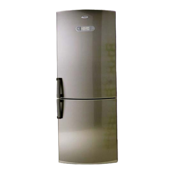
3 – AESTHETICS CHARACTERÍSTICS Their main characteristics are: Easy Ice system with automatic feeder, External Handle, Electronic Control for both Compartments (Refrigerator - RC and Freezer - FC) with LCD Display & Skin Condenser (Clinched Condenser). 1- Lamp, refrigerator 11- Rollers (4) 2- Glass shelf (3) 12- Leveler Feet (2) 3- Wind Flow System (air outlets) -
Page 6: Use Characteristics
4 – USE CHARACTERISTICS 4.1 – Keys selection on the Control Panel This product has 2 differents electronic temperature controls for which compartment, both located at the Refrigerator Door on the Interface Panel – LCD Display. When the product is connected for the first time to the Electrical power supply, the digital panel (LCD) light up for 2 seconds (all icons will appear) and the buzzer will beep once, then the presentation mode will be activated (around 10 seconds), after that, 5 C pre-selected Refrigerator temperature will appear... -
Page 7: Functions & Indicative Icons On The Lcd Display
4.2 – Functions & Indicative Icons on the LCD Display 4.2.1. For Refrigerator Compartment • Temperature selection for the Refrigerator Compartment It can be selected degree by degree (positive temperature) for the Refrigerator Compartment from 1º C (maximum – colder ) to 7º C (minimum –... -
Page 8: For Freezer Compartment
• Open Refrigerator door Icon Whenever the refrigerator Door is open, this icon will activate, showing the door status. If it is flashing, it means the product is in the Alarm mode (see Alarm system – item). 4.2.2. For Freezer Compartment •... -
Page 9: Informative And Alarm Icons
• Open Freezer door Icon Whenever the freezer Door is open, this Icon will activate, showing the door status. If it is flashing, it means the product is in the Alarm mode (see Alarm system – item). 4.2.3. Informative and Alarm Icons •... -
Page 10: Electronic Control
These components are described as shown below. 5.1. Electronic Control The complete operation of this product is done by the Electronic Control, which executes the functions according to the needs, turning the components on or off through received/managed signals, such as: - Compressor On/Off - Fan Motors (Refrigerator &... - Page 11 Disassembly 1. Remove the cover fastening screws. 2. Release the cover tabs. 3. Release the Board connectors. 4. Loose all other screws and remove the Electronic Control. IMPORTANT # Be careful when using the Multimeter # Be careful when removing the electronic board measuring probes, as they may damage the connectors, as they are latched.
-
Page 12: Interface Board
5.2. Interface Board – LCD Display The interface board has the function of interacting with the user, indicating the product functions/programming and operation (see Use Characteristics item) always put in operation by the Electronic Control. Disassembly - LCD 1. Pry the Buttons (right & left) of 2. -
Page 13: Freezer Fan Motor
Disassembly 1. Remove both screws that are fastening the 2. Release the connector and pull out the set Console 5.4. Freezer Fan Motor The Freezer Fan Motor is fed by direct voltage (Vdc) and fixed to the rear cover of the evaporator through a rubber flexible holder, that protects from occasional vibrations, and consequently noise. -
Page 14: Refrigerator Fan Motor
5.5. Refrigerator Fan Motor The Refrigerator Fan Motor is also fed by direct voltage (Vdc), therefore, located inside the Wind Flow, fixed to a plastic Housing by flexible rubber holder, which avoids occasional vibrations and consequently noise. It is responsible for the forced air circulation inside the Refrigerator Compartment. This component does not depend on the compressor to work, and its speed (rpm) can range according to the function/necessity managed by the Electronic Control. -
Page 15: Refrigerator Temperature Sensor - Ntc
When the product is for the first time connected to the Electrical power supply and the initialization routine was finished (See User Characteristics) the digital panel (LCD) will start with the factory pre- selected temperatures: • Freezer = 3 dashes (then, –18 •... - Page 16 -40,5 93778,7 -15,5 20142,8 5466,7 34,5 1788,8 -40,0 90695,7 -15,0 19582,8 10,0 5336,8 35,0 1752,2 -39,5 87724,3 -14,5 19040,1 10,5 5210,4 35,5 1716,4 -39,0 84860,2 -14,0 18514,1 11,0 5087,4 36,0 1681,4 -38,5 82099,2 -13,5 18004,3 11,5 4967,6 36,5 1647,3 -38,0 79437,2 -13,0 17510,2...
-
Page 17: Freezer Temperature Sensor - Ntc
5.6.2. Freezer Temperature Sensor – NTC Located on the freezer compartment at the Evaporator Front Cover, the Freezer temperature Sensor is responsible for internal temperature monitoring of this compartment, sending signs to the Electronic Control which will activate/ deactivate Compressor and Fan Motor (thermostatic routine), keeping the internal temperature close to the desired/ selected on the Interface Panel Right... - Page 18 WARNING These Sensors (Freezer & Defrost) Are Compatible with Each Other, but Are Not Compatible with the Sensors of the previous line. NEVER replace these Sensors with the Sensor Kit used in the previous line. Replacement In the need of replacing one of the Temperature Sensors, use the SENSOR KIT (code 326.013.997), which consist in;...
-
Page 19: Defrost System
IMPORTANT ♦ Only press the metal blade after ensuring that the wires are touching the connector bottom. ♦ Do not remove the silicon grease from inside the connector, for this grease protects the wire terminals against moisture and rust. 6) Take the other connector and repeat the operation with the other wires, then put the Sensor at its origin position. -
Page 20: Alarm System
5.8. Alarm System Should the product present any irregularity (according the possibilities below), it will set off a sound (“BEEP”) and/ or visual Alarm (Icon blinking), through the LCD Interface, getting the diagnosis easy. Before visiting a client requiring service, we must request to the consumer if any Alarm or failure Code is been shown on the LCD display (Interface Board) ATTENTION When one of these faults occur, the client must be instructed to turn off the sound alarm by pressing the... -
Page 21: C) Open Door Alarm
c) Open door Alarm When any of the doors (Freezer or Refrigerator) remains open more than 2 minutes, the Electronic Control system will emit a sound Alarm - “BEEP” , the Open Door icon (corresponding to the compartment/ door) will blink and the Caution Alarm Icon will switch on, indicating that it’s open. -
Page 22: Service Call Alarm
5.8.2. Service Call Alarm a) Communication Failure Alarm This failure mode is shown at the LCD Display through the Failure Code – “CF” and Service Call Icon blinking. This failure is caused due to a communication fault between the Interface Board (LCD Display) and the Electronic Control. To disable teh sound Alarm, just press the Turn off Alarm key (OK) When constant, there is the chance of a real Technical Failure, check its source. -
Page 23: Air Flow
5.9 – Air flow The flow of forced air circulates inside the product by the action of 2 Fan Motors (Dual Fan), one located on Freezer Compartment and the other on Refrigerator Compartment. Refrigerator The Air is directed through ducts provided with different Fan Motor paths as illustrated in the figure. - Page 24 Disassembly For accessing the Freezer internal components remove the sensor Support, the Sensor itself (from the Support) and then disconnect the FC Fan Motor Connector. Finally, just loosen the 4 screws at the sides of the Cover and pull it out. Remove Remove Remove...
-
Page 25: Air Circulation Into Refrigerator Compartment
5.9.2 – Air circulation into Refrigerator Compartment Cold air is blown into the refrigerator compartment by the Freezer Fan Motor that “pushes” the air through the Evaporator Cover (1) reaching the internal Duct (2) and at the same time is “pulled” by the refrigerator Fan Motor (exhauster), following to the refrigerator Diffuser/ducts (3) and going out through the outlets/ windows at the different levels of the Wind Flow (Internal Refrigerator Diffuser). -
Page 26: Others Components
3- Open the EPS Diffuser, locate the refrigerator Note: Fan Motor and Membrane details. Fan Motor and the Membrane . Remarks: Be aware with the Fan Motor position to avoid cooling problems after reassembling; Take care to not damage the seals, in case of damage replace them by new ones that are available as Spares. -
Page 27: Compressor
6.3 – Compressor: This model is fitted with Embraco Compressor’s, which is prepared to work only with the R-600a Fluid and can only be replaced with another of the same type. Description Characteristics Embraco – EGM90CLC 166W – 220-240/50-60Hz Remark The Electronic Control System of the product holds a safety device that allows the compressor to be turned on 7 minutes after its last power down This prevents the Compressor from attempting to start... - Page 28 WARNING Be careful when handling the Evaporator, due to it blades has sharp edges and can cut your hands. Always wear protective gloves. The sides of the Evaporator are provided with 2 EPS shims that will cause the whole of the return air to pass through the Evaporator instead its sides.
-
Page 29: Defrost Heater
c) Install the new Evaporator and the Lokring connectors, do Vacuum in the system followed by the original load of R-600a. REMINDER • DO NOT USE ANTI-FREEZING AGENTS (e.g. Methyl Alcohol) on the Sealed System reoperation, as these agents damage the Compressor. Only technicians skilled in the operation of Isobutane Sealed Units are authorized to maintain the products. -
Page 30: Refrigerator Lamp
6.10 – Refrigerator Lamp: The ARC8140IX use a special refrigerator Lamp with 25-W, however, the freezer compartment has no lamp/lighting. This refrigerator lamp is located on the (refrigerator) compartment ceiling; to replace it, slide the lamp protector, pulling it out and then take the Lamp out. CAUTION To replace the lamp, do not turn it as it has no thread. -
Page 31: Anti-Bacteria Filter
6.15 – Anti-Bacteria Filter: The Refrigerator is fitted with a "special" Anti-Bacteria Filter located behind of the vegetable Drawer at the refrigerator air return. This filter acts by absorbing characteristic odors and bacterias of certain food which circulate inside the product. It thereby prevents these foods from losing their natural flavor and smell characteristics. -
Page 32: Interface Board - Lcd Display Routine
REMARKS 1- This routine always starts when the product is pluged in and has priority over other commands done on the Interface; 2- During this initial automatic test routine, if the Doors are open, the Fan Motor won’t be deactivated; 3- If the product is in Defrosting mode, this routine will be aborted due to defrost mode has priority over all functions The routine ending will be in 5 minutes and 48 seconds. -
Page 33: Door Reversal
8 – DOOR REVERSAL This Refrigerator comes assembled from the factory, with the doors opening towards the right side (hinges and bushings are located on the right side, when facing the product). In order to change the doors opening, that is, to cause it to open towards the left side, the specific left- hand clicking bushings (Refrigerator &... - Page 34 • Remove the upper Hinge screws and then the Hinge itself; • Remove the Refrigerator Door; • Hide the wire connector into the cabinet housing, then remove the plastic cover from left side and place it on the right-hand; • On the left side of the cabinet, release the hidden wire connectors, then, disconnect them keeping the female connector outside to plug it later on at the freezer Door connector.
- Page 35 3- Disassembling the Freezer Door • Loose the screws of the intermediary hinge • Remove the Freezer Door • Remove the plastic cover and place it on the right-hand side of the rail 4- Preparation of the Plinth / lower Hinge: •...
- Page 36 • On the right, law the cable under the end cap housing; • While in the opposite side, disconnect the hidden cables, keeping the male connector outside and the female connector inside the end cap housing; • Close the end caps housing, reassembling the finishing plastic cover (in the right side) and the plastic cover &...
- Page 37 6- Doors Assembling: • Position the Freezer Door, check for its alignment and then fasten the intermediary hinge • Place the Refrigerator Door and engage the upper hinge into that Door • Connect the interface board (LCD Display) wiring connectors •...
-
Page 38: Required Tools For Servicing
• Close the door orifices using the plugs provided with the Kit • On the left-hand side, remove de door plugs. • Finally, assembly the Handles inverting its position and fastening the allen Screws. 9 – REQUIRED TOOLS FOR SERVICING ♦... -
Page 39: Wiring Diagram
10 – WIRING DIAGRAM MSEX0105i – Electronic No Frost Refrigerator Bottom Mount/ Dual Fan - Maestro High... -
Page 40: Failure Correction Chart (Troubleshooting)
11 – FAILURE CORRECTION CHART (TROUBLESHOOTING) COMPLAINT CHECK SOLUTION If the Power Cable is connected. Connect it If the wall outlet is powered. If not, advise the consumer to call an electrician. If the circuit breaker is tripped or if the Reset the circuit breaker or advise the home fuse is opened. - Page 41 COMPLAINT CHECK SOLUTION If the evaporator is blocked by ice. Check the defrost system: -Defrost Sensor should not be opened, in short-circuit or out of position (evaporator returning pipe) -Defrost Heater & Thermofuse are opened/ burnt or improperly positioned -The Electronic Control – PCB should be engaging the Defrost Heater, do the self test routine to prove it.
- Page 42 COMPLAINT CHECK SOLUTION Food on the If Vegetable Tray Humidity Regulator Adjust the Humidity Regulator to a Vegetable Tray is closed. more open position. sweating. If the Lamp is burnt Replace the Lamp. If not, check: -Reed switch board Lamp not light on -Magnetics inside the end cap doors -Wirings and connectors between Electronic Control and LCD (Interface)
Need help?
Do you have a question about the Multibras ARC8140IX and is the answer not in the manual?
Questions and answers