Advertisement
Quick Links
1 | Overview
This module adds a maximum of 2A of 12 VDC power for Fire
and Burglar standby power applications.
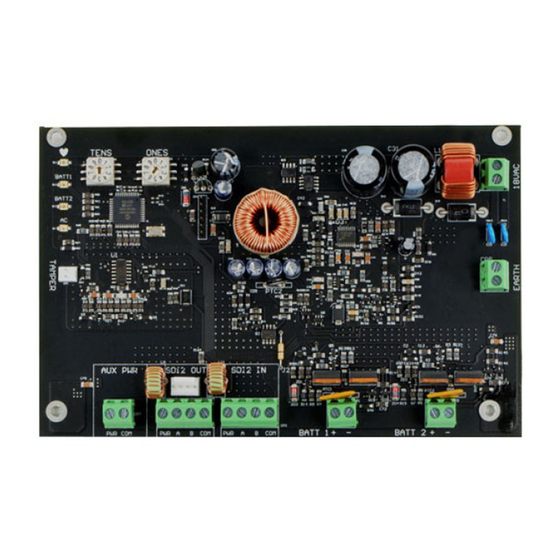
Callout ― Description
1 ― Address switches
2 ― EARTH ground connector terminal
3 ― 18 VAC transformer input terminal
4 ― BATT 1 and BATT 2 terminals
5 ― SDI2 IN terminals (from control panel)
6 ― SDI2 OUT terminals and interconnect wiring connector
7 ― Auxiliary power terminals
8 ― Tamper switch connector
9 ― AC LED
10 ― BATT 1 and BATT 2 LEDs
11 ― Heartbeat LED
2 | SDI2 address settings
The control panel uses the address for communications. Use
the control panel configuration to set the address switches. If
multiple modules are on the same system, each module must
have a unique address.
NOTICE!
The module reads the address switch setting only
during power up. Cycle the power to the module in
order for the new setting.
2.1 | Setting the address settings
1.
Set the switches using a screwdriver.
2.
For single-digit address numbers 1 through 9, set the
tens switch to 0 and the ones switch to the appropriate
number.
The following illustration shows an example of address "12."
3 | Installation
The enclosure holds the module. Wires attach the module to the
control panel, SD12 expansion modules, and any other device.
NOTICE!
Remove all power (AC and battery) before making any
connections. Failure to do so might result in personal
injury and/or equipment damage.
3.1 | Install the module in the enclosure
(models B10, D2203, AE1, and AE2)
NOTICE!
Do not use B10 or D2203 enclosures for Commercial
Fire applications.
1.
Install the mounting clips onto the appropriate standoff
locations inside the enclosure. Callout # 3 in the
following illustration.
2.
Put the module onto the mounting clips.
3.
Attach the module with mounting screws.
Callout ― Description
1 ― Mounting screws
2 ― B10, D2203, AE1, and AE2 enclosures
3 ― Standoff locations
4 ― Plastic mounting clips
5 ― Batteries (up to two 7 Ah or one 18 Ah batteries)
6 ― B520 module
3.2 | Attaching the grounding wire
(models B10, D2203, AE1, and AE2)
1.
Put the grounding wire lug onto the bolt
2.
Attach it with a nut and a washer.
3.
Put the other end of the wire onto the door hinge.
3.3 | Attach the module in the enclosure
(model B8103)
The enclosure attaches to a B12 mounting plate.
3.4 | Mount the B12 mounting plate
in the enclosure (model B8103
)
1.
Put the mounting plate in the back of the enclosure.
2.
Set the tabs of the enclosure into the two mounting
skirt hooks.
3.
Attach the tab to mounting hole with the screw. Refer to
the following illustration.
Callout ― Description
1 ― B8103 enclosure (also applicable for BATB-40)
2 ― Support posts
3 ― Mounting plate
4 ― Lock down tab
5 ― Plate mounting hole
6 ― Mounting plate hooks
3.5 | Attaching the module onto the
mounting plate
Refer to Section 3.1 for installation steps as well as the fol-
lowing illustration.
7
7
Callout ― Description
1 ― Mounting screws
2 ― B520 module
3 ― B8103 Enclosure (applicable for BATB-40 as well)
4 ― B12 mounting plate
5 ― Plastic mounting clips
6 ― Batteries (holds up to two 7 Ah or two 18 Ah batteries)
NOTICE!
To help prevent damage from electrostatic charges or
other transient electrical surges, connect the system
to earth ground before making other connections.
1.
Use 14 AWG (1.6 mm) to 16 AWG (1.3 mm) wire for the
connection. Do not use telephone or electrical ground.
2.
Use a grounding rod or a cold water pipe.
3.
Install the wire as close as possible to the grounding
device.
NOTICE!
Finland: Laite on liitettävä suojakoskettimilla
varustettuun pistorasiaan.
Norway: Apparatet må tilkoples jordet stikkontakt.
Sweden: Apparaten skall anslutas till jordat uttag.
Advertisement

Related Manuals for Bosch B520


Summary of Contents for Bosch B520
- Page 1 1 ― Mounting screws The enclosure attaches to a B12 mounting plate. 4 ― BATT 1 and BATT 2 terminals 2 ― B520 module 5 ― SDI2 IN terminals (from control panel) 3.4 | Mount the B12 mounting plate 3 ― B8103 Enclosure (applicable for BATB-40 as well) 6 ―...
- Page 2 B810 x Quantity = x Quantity from “Table B” is bigger than 4A, then use a second B520 to D125B ― Loop A only x Quantity x Quantity split the current load.
- Page 3 Premise Alarm Control Units CAN/ULC S545 - Residential Fire Warning Con- Copyright trol System This document is the intellectual property of Bosch Security Systems, Inc. and is protected by copyright. All rights reserved. ULC-ORD C1023 - Household Burglar Alarm Trademarks System Units All hardware and software product names used in this document are likely to be registered trademarks and must be treated accordingly.
Need help?
Do you have a question about the B520 and is the answer not in the manual?
Questions and answers