Table of Contents
Advertisement
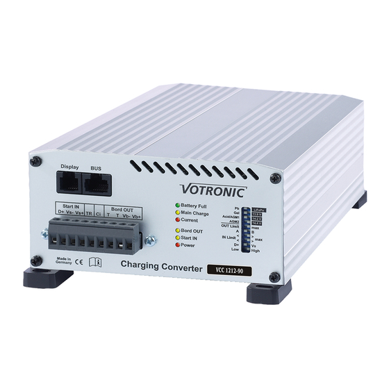
Installation and Operating Manual
Charging Converter, B2B Battery to Battery, Optimal Battery Charging During Driving:
VCC 1212-50
VCC 1212-70
VCC 1212-90
Please read the mounting instructions and the operating manual including the safety
instructions attentively.
Particularly observe page 19 "Safety Regulations and Appropriate Application",
prior to starting connection and start-up.
Fully automatic Battery Charging Converter for special purpose vehicles, high-quality campers, boats.
The charging converters (boosters) of series "VCC" have been developed according to the latest regulations for supply
battery (living area/board batteries) charging, mobile from the generator (starter battery) during driving.
In contrast to conventional cutoff relays, the charging voltage will be raised or lowered according to the default values of
the charging program. Thus, they are particularly suitable for vehicles according to the EURO Standard 6, 6 +.
Eight (8) selectable charging programs for conventional board batteries in lead- acid, lead-gel, lead-AGM or advanced
lithium LiFePO4 technology ensure unattended, quick and gentle full charging from any charging state with subsequent
trickle charging and maintenance of the battery.
Even at short distances, the battery will be charged with full charging current. The simultaneous supply of the connected
12 V consumer loads is effected automatically, even in case of strongly loaded board mains. The automatic power control
gives the required safety and ensures the vehicle's starting ability.
The efficient charging converter ensures high charging capacity, already within short distances.
Full charging when driving longer distances.
It increases/reduces the voltage to the level, which is required for precise charging of the board battery with the
optimum charging characteristic line.
Cable losses and considerable voltage fluctuations of the generator, known from Euro 6 vehicles (intelligent generators),
are completely compensated.
The charging converters excel by their compact design, low weight (high-frequency switch mode technology) and
powerfully dimensioned power components for safe operation.
Significantly improved energy balance of the board battery.
There is no intervention into the starter circuit. The unit acts like a powerful consumer at the generator.
The simultaneously supplied 12 V consumer loads are protected against overvoltage and voltage fluctuations.
Further Characteristics of the Unit:
The charging voltage is free from peaks and is controlled in such a way, that overcharging of the batteries is excluded.
Fully Automatic Operation: The unit is permanently connected to the batteries, and it is automatically activated by the
running generator of the vehicle. Battery discharge in case of an engine stop is avoided.
Parallel and Floating Operation: In case of simultaneous consumption, the battery will either continue to be charged or
maintained via trickle charging. Calculation and control of the adaptation of the charging times is effected automatically
by the unit.
Unattended Charging: Multiple protection against overload, overheating, overvoltage, short circuit, incorrect behaviour
and back discharge of the battery by electronically controlled gradual reduction down to complete separation of unit
and battery.
Integrated On-board Mains Suppression Filter: Unproblematic parallel operation of charging sources (EBL, chargers,
motor-driven and petrol-driven generators, solar systems) on one battery.
Charging Cable Compensation: Automatic compensation of voltage losses on the charging cables.
Connection for Battery Temperature Sensor (included in the standard delivery scope):
Lead batteries (acid, gel, AGM): In case of low outside temperatures, full charging of the weak battery is improved by
automatic adaptation of the charging voltage to the battery temperature, and in case of summery temperatures
unnecessary battery gassing will be avoided.
Lifepo4 Batteries: Battery protection in case of high temperatures and particularly adapted charging in case of low
temperatures below 0 °C.
Charging aid for deeply discharged lead batteries: Gentle preliminary charging of the (lead-acid, gel, AGM) battery to 8
V, followed by powerful support of the battery, in case of possibly switched-on consumers.
Ensures also automatic activation of a LiFePO4 battery, which had been switched off by the BMS.
Input Voltage 12 V
Input Voltage 12 V
Input Voltage 12 V
Charging Capacity 12 V / 50 A
Charging Capacity 12 V / 70 A
Charging Capacity 12 V / 90 A
No. 3326
No. 3328
No. 3329
Advertisement
Table of Contents

Related Manuals for Votronic VCC 1212-50

Summary of Contents for Votronic VCC 1212-50
- Page 1 Installation and Operating Manual Charging Converter, B2B Battery to Battery, Optimal Battery Charging During Driving: VCC 1212-50 No. 3326 Input Voltage 12 V Charging Capacity 12 V / 50 A VCC 1212-70 No. 3328 Input Voltage 12 V Charging Capacity 12 V / 70 A VCC 1212-90 No.
- Page 2 Special case: In case of a cutoff relay of the customer, which exists in the vehicle and which is in a very difficult to access location or which is not accessible. Only suitable for VCC 1212-50, page 6. Special case: In case of temporarily very high consumer current rates, such as with operation of a body air-conditioner during driving with powerful inverter, page 7.
- Page 3 --3-- Standard Connection Plan incl. Options, All Types: Safety Instructions for All Connection Methods: Observe the cross-sections and lengths of the cables. Never mix up the voltage sensor cables for start (Vs- and Vs+) and board (Vb- and Vb+)! ...
- Page 4 In combination with electroblock "EBL", "EVS" with further use of the cabling and fuses, which are already existing in the vehicle, the cable to the starter battery must be disconnected. Only suitable for VCC 1212-50: The cabling and the fuses for the electroblock EBL provided by the customer are further used.
- Page 5 --5-- In combination with electroblock "EBL", "EVS" with the existing cabling of the customer, however with separate VCC cabling, suitable for all VCC types 50 / 70 / 90 with full capacity: The cabling and the fuses for the electroblock EBL provided by the customer are further used. For this purpose, insert a switching relay 12 V / 60 A, order No.
- Page 6 Special case: In case of a cutoff relay of the customer, which exists in the vehicle and which is in a very difficult to access location or which is not accessible, disconnect the cable to the starter battery. Only suitable for VCC 1212-50: The cabling with the fuses and the cutoff relay provided by the customer are further used.
- Page 7 --7-- "TR" Bypass Relay: Special case: In case of temporarily very high consumer current rates exceeding the maximum charger current of the charging converter, such as with operation of a body air-conditioner during driving with powerful inverter: Instructions for faultless function of this option: Connect the charging converter VCC and the "TR"...
- Page 8 --8-- Tables 1: Recommended Cable Cross-Sections, Cable Lengths and +Fuse Capacities Configuration of the 3 large capacity terminals "Com. –", "OUT Board +", "IN Start +": The central connection point of all minus cables for units and batteries is the – pole of the board battery ...
- Page 9 --9-- Connection of the 9-pole Plug-in Terminal Strip (Sensor Inputs, Terminal): Plug-in Terminal Strip: In case of limited space, the strip can be removed and reinserted at any time for easy cable connection. Cable Cross-Sections: 0,75 mm or more. Length to be stripped: approx. 6 mm. Protection: All inputs and outputs of this terminal strip are protected against overvoltage, reverse battery and overload.
- Page 10 --10-- Connection "Display": Plug-type connection for either a LED Remote Control S (order No. 2076) or an LCD Charge Control S-VCC (order No. 1248). Further information can be found in the corresponding operating manual. Battery Temperature Sensor: Connect the temperature sensor (included in the standard delivery scope) to the terminals "T T" (any polarity). The temperature sensor controls the temperature of the board supply battery.
- Page 11 --11-- Unit Settings: Carefully move the 10 micro slide switches behind the front panel of the unit to the desired position using a small screw-driver. The control levers are shown in white. How to Set the Battery Type "Board"- (Design, Technology): Eight (8) charging programs for the different battery types are stored in the unit.
- Page 12 --12-- 3 "AGM 1 14.4 V" Switch Position U1=14.40 V U2=13.50 V 1.5-5 h Adapted to closed, gas-tight AGM (absorbed glass mat)/lead-fleece batteries VRLA with indicated charging voltage "14.4 V". 4 "AGM 2 14.7 V" Switch Position U1=14.70 V U2=13.60 V 1.5-5 h Adapted to closed, gas-tight AGM (absorbed glass mat)/lead-fleece-...
- Page 13 --13-- The charging regulations of the battery manufacturer are absolutely to be observed! An operation of the unit at a LiFePO4 battery without BMS Battery Management System and without equalization charging of the cells (balancing) as well as safety circuit is not admissible! ...
- Page 14 --14-- Further Settings and Functions, 6 Slide Switches: OUT Limit – max (Reduction of the charging current to the board battery): Output side of the charging converter: The switch can be used to limit the maximum charging current, in order to be able to charge also smaller batteries or to avoid an overload of an existing electroblock EBL of the customer: Table 2: VCC 1212 - 50...
- Page 15 --15-- How to set the operating mode of the starter battery (IN, input side) The automatic control (activation) of the charging converter after the engine start can be executed in two different ways: In case of special applications, voltage-controlled by the increased voltage of the starter battery with running engine (not for EURO 6 vehicles!) ...
- Page 16 --16-- Pilot Lamps: "Battery Full" (Board battery fully charged, green): If it is on: Battery has been charged to 100 %, trickle charge U2, finished. If it is flashing: Main charging process is effected in the charging phase U1, indication of the charging state of 75 % (lead), approx.
- Page 17 --17-- Start-up and Function Test: After connection and setting of the charging converter, the function can be tested: Start the vehicle: The charging converter will be activated and starts with 3% of the maximum charging capacity. The LEDs "Power”, "Start IN”, "Board OUT” and "Main Charge" will be lighting, LED "Current” is lighting dimly. Increase the speed of the vehicle to increase the voltage at the starter battery until it exceeds the adjusted value for the "increase of the charging capacity".
- Page 18 --18-- Chronological Sequence at the Board Battery (OUT): A new, complete main charging cycle will be executed: After a standstill of the generator or removal of the control signal "D+". If the voltage of the starter battery has dropped below the adjusted switching off threshold for more than 30 seconds. ...
- Page 19 The liability exclusion is extended to any service being executed by third, which has not been ordered by us in writing. Service is to be effected exclusively by VOTRONIC Lauterbach. Declaration of Conformity: In accordance with the provisions of Directives 2014/35/EU, 2014/30/EU, 2009/19/EC, this product complies with the following standards or normative documents: EN55014-1;...
- Page 20 Subject to misprints, errors and technical modification without notice. All rights reserved, particularly the right of reproduction. Copyright VOTRONIC 04/18. Made in Germany by VOTRONIC Electronic-Systeme GmbH & Co. KG, Johann-Friedrich-Diehm-Str. 10, 36341 Lauterbach/GERMANY Phone: +49 (0)6641/91173-0 Fax: +49 (0)6641/91173-20 E-mail: info@votronic.de...
Need help?
Do you have a question about the VCC 1212-50 and is the answer not in the manual?
Questions and answers