Advertisement
Quick Links
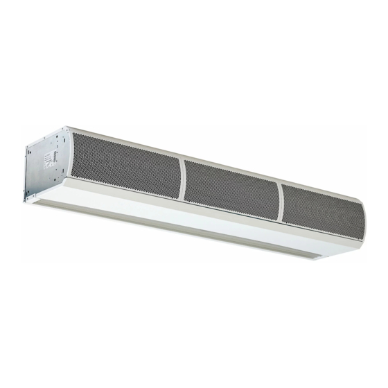
PHV V NT VERTICAL AIR CURTAINS
INSTALLATION, OPERATION & MAINTENANCE INSTRUCTIONS
PLEASE READ THESE INSTRUCTIONS CAREFULLY BEFORE ATTEMPTING INSTALLATION
Thermoscreens Ltd
St. Mary's Road Nuneaton
Warwickshire England
CV11 5AU
Email:
sales@thermoscreens.com
Tel: +44 (0) 24 7638 4646
Fax: +44 (0) 24 7638 8578
www.thermoscreens.com
9901020-6
Page 1 of 25
Advertisement

Related Manuals for Thermoscreens PHV V NT series


Summary of Contents for Thermoscreens PHV V NT series
- Page 1 PHV V NT VERTICAL AIR CURTAINS INSTALLATION, OPERATION & MAINTENANCE INSTRUCTIONS PLEASE READ THESE INSTRUCTIONS CAREFULLY BEFORE ATTEMPTING INSTALLATION Thermoscreens Ltd St. Mary’s Road Nuneaton Warwickshire England CV11 5AU Email: sales@thermoscreens.com Tel: +44 (0) 24 7638 4646 Fax: +44 (0) 24 7638 8578 www.thermoscreens.com...
- Page 2 UN-PACKING YOUR PHV V NT VERTICAL AIR-CURTAIN The following items are supplied and packaged within the boxes. PHV V NT Vertical Air Curtain Remote Control Motorised Valve Accessories (LPHW units only) M10 stainless steel dome nuts Wall fixing kits Stacking kit (spacer plate, M8 x 25 bolts and M8 nyloc nuts) for stacked units If anything is missing or damaged please contact your place of purchase immediately.
- Page 3 INSTALLATION OF YOUR VERTICAL APPLICATION PHV V NT AIR CURTAIN The air curtain must be surface mounted within the building and not exposed to the external environment or moist conditions. Do not install the air curtain in a doorway situation where there is a likelihood, or there has been a history of, rain ingress.
- Page 4 Remove only one M10 nut and refit and resecure bolt with a stainless steel M10 dome nut supplied. Repeat for each of the other three projecting bolts one at a time. Stacking of Units PHV1500V and PHV2000V air curtains are delivered as single units. PHV2500V and PHV3000V air curtains are delivered as separate 1.5m + 1m air curtains for a PHV2500V unit and 2m + 1m air curtains for a PHV3000V unit.
- Page 5 9901020-6 Page 5 of 25...
- Page 6 Safety and Electrical Connections All electrical wiring and connections MUST be carried out by a competent qualified electrician in accordance with the latest edition of the IEE wiring regulations and/or local statutory regulations. A single phase or 3 phase local isolator with a contact separation of at least 3mm in all poles must be fitted to the supply wiring (the isolator must be fitted in an accessible position).
- Page 7 To gain access for making electrical and/or water services the air intake grilles must be removed. Remove intake grilles by unfastening two screws on each grille; M4 x 10mm Pozi screws accessed via larger hole in the side of the grille (See Insert).
- Page 8 Two Air Curtains in a Stack When two air curtains are in a 2.5m or 3m stack the Ecopower control wiring needs to be wired “master/slave”, so the RJ master/slave cable safely routed internally between air curtain stack is controlled by a single circuit boards of top and Ecopower remote control.
- Page 9 LPHW Models 22mm pipe For LPHW models ensure suitable water mains isolation valves are 15mm 22mm pipe pipe fitted in the flow and return 22mm pipe pipework. When fitting the 3-port valve ensure that the pipe connections are fitted as detailed and are in accordance with the manufacturers leaflet Optional 1m Stack Unit supplied with the valve.
- Page 10 Ecopower Controller Motherboard (v8) Function Control Comments Standard Fan Heat Interlock for Electric DIP1 Maximum heat output achieved if As supplied, for electric maximum fan speed selected. heated air curtains the Heated Air Curtains– Independently set-up DIP switch on default setting for heat The heat output is dependent on the fan each mother board.
- Page 11 DIP switches fitted on the Ecopower board provide a selection of optional features as described above. Isolate and switch electrical power off before configuring and/or changing any DIP switch settings. • Easy plug-in arrangement for remote air sensor thermistor on a 1m lead. Plugging-in the remote air sensor to J3 disables the standard air sensor thermistor already fitted on the Ecopower board.
- Page 12 9901020-6 Page 12 of 25...
- Page 13 9901020-6 Page 13 of 25...
- Page 14 9901020-6 Page 14 of 25...
- Page 15 9901020-6 Page 15 of 25...
- Page 16 9901020-6 Page 16 of 25...
- Page 17 9901020-6 Page 17 of 25...
- Page 18 9901020-6 Page 18 of 25...
- Page 19 9901020-6 Page 19 of 25...
- Page 20 9901020-6 Page 20 of 25...
- Page 21 9901020-6 Page 21 of 25...
- Page 22 Ecopower Remote Control Operation Higher Fan Speed Higher Heat Auto Mode On / Off Lower Heat Auto on Indicator Fan Speed Indicator Lower Fan speed Heating Level Indicator Push On/Off switch to turn On, then operate as follows :- Auto Switches between manual and automatic heat regulation.
- Page 23 In the case of a fault condition (refer to flowchart) do not attempt to reset the thermal cut outs or replace the fuses. Arrange for a Thermoscreens appointed technician or certified electrician to attend the unit to investigate the reason why the thermal cut outs/fuse(s) have operated.
- Page 24 User Fault Finding Flowchart (for Ecopower Control) Is Electrical Switch on Electrical Power Power switched on Connect remote control Service Agent to and push On/Off switch reset thermal cut- to turn unit on out(s) Are the fans operating correctly Is the remote Do the LED’s Service Agent to control...
- Page 25 Warranty If any problems are encountered, please contact your installer/supplier. Failing this please contact the Thermoscreens warranty department. All units are covered by a two year warranty period. Care has been taken in compiling these instructions to ensure they are correct, although Thermoscreens disclaims all liability for damage resulting from any inaccuracies and/or deficiencies in this documentation.
Need help?
Do you have a question about the PHV V NT series and is the answer not in the manual?
Questions and answers