Table of Contents
Advertisement
Advertisement
Table of Contents
Troubleshooting

Related Manuals for Keysight 85024A


Summary of Contents for Keysight 85024A
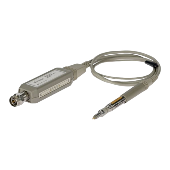
- Page 1 Keysight 85024A High Frequency Probe User’s and Service Guide...
- Page 2 Conformity. understood and met. where in the EULA. Keysight shall be under no obligation to update, revise or otherwise modify the Software. With WARNING respect to any technical data as defined by FAR 2.101, pursuant to FAR...
-
Page 3: Warranty
Warranty This product is warranted against defects in material and workmanship for a period of one year from date of shipment. During the warranty period, Keysight Technologies will, at its option, either repair or replace products which prove to be defective. -
Page 4: Assistance
This represents a “softkey”, a key whose label is determined by the instrument firmware. Environmental Conditions The 85024A is designed for indoor use and in an area with low condensation. The table below shows the general environmental requirements for this instrument. Environmental cond ition... -
Page 5: Regulatory Markings
This symbol is a South Korean Class A EMC Declaration. This is a Class A instrument suitable for professional use and in electromagnetic environment outside of the home. Keysight 85024A User’s and Service Guide... -
Page 6: Waste Electrical And Electronic Equipment (Weee) Directive
To return this unwanted instrument, contact your nearest Keysight Service Center, or visit http://about.keysight.com/en/companyinfo/environment/takeback.shtml for more information. Sales and Technical Support To contact Keysight for sales and technical support, refer to the support links on the following Keysight websites: – www.keysight.com/find/rfprobes (product-specific information and support, software and documentation updates) –... -
Page 7: Table Of Contents
........26 Keysight 85024A User’s and Service Guide... - Page 8 ..........51 Keysight 85024A User’s and Service Guide...
- Page 9 ........... .77 Keysight 85024A User’s and Service Guide...
- Page 10 THIS PAGE HAS BEEN INTENTIONALLY LEFT BLANK. Keysight 85024A User’s and Service Guide...
-
Page 11: List Of Figures
..72 Figure 7-11 Regulator parts and wiring .....73 Keysight 85024A User’s and Service Guide... - Page 12 THIS PAGE HAS BEEN INTENTIONALLY LEFT BLANK. Keysight 85024A User’s and Service Guide...
-
Page 13: List Of Tables
....51 Table 6-2 Replaceable parts ......52 Keysight 85024A User’s and Service Guide... - Page 14 THIS PAGE HAS BEEN INTENTIONALLY LEFT BLANK. Keysight 85024A User’s and Service Guide...
- Page 15 Keysight 85024A High Frequency Probe User’s and Service Guide General Information Read This Before Using Your Probe Anti-Static Precautions Product Description Specifications and Characteristics...
-
Page 16: General Information
– Higher sensitivity is required than is possible with the 10:1 divider attached. When the probe is stored, attach the 10:1 divider and place the anti-static protection cap over the probe tip. Figure 1-1 Probe with 10:1 divider and anti-static protection cap Keysight 85024A User’s and Service Guide... -
Page 17: Anti-Static Precautions
Do not introduce ESD into the device under test (DUT) while the probe is in use. If an unprotected person touches part of the DUT, a static charge could damage the DUT as well as the probe. Keysight 85024A User’s and Service Guide... -
Page 18: Product Description
The probe tip may be inserted into the supplied probe adapter, adjusting the probe tip to a 50 W type-N male connector. The probe’s output connector is a type-N male. Keysight 85024A User’s and Service Guide... -
Page 19: Specifications And Characteristics
General Information Specifications and Characteristics For the specifications and characteristics of the 85024A High Frequency Probe, refer to the data sheet at http://literature.cdn.keysight.com/litweb/pdf/ 5968-2101E.pdf Keysight 85024A User’s and Service Guide... - Page 20 General Information THIS PAGE HAS BEEN INTENTIONALLY LEFT BLANK. Keysight 85024A User’s and Service Guide...
-
Page 21: Accessories
Keysight 85024A High Frequency Probe User’s and Service Guide Accessories Probe Features and Accessories Probe Adapter 10:1 Divider... -
Page 22: Probe Features And Accessories
Accessories Probe Features and Accessories Figure 2-1 Probe features Keysight 85024A User’s and Service Guide... -
Page 23: Table 2-1 Probe Features
External DC power supply adapter cable [a] Used with the 85046A s-parameter test set. [b] Used with the 8590A spectrum analyzer. [c] Requires the E3620A, E3630A, or E3631A External Power Supply from Keysight Technologies. Keysight 85024A User’s and Service Guide... -
Page 24: Probe Adapter
Periodically inspect the threads of the adapter for signs of wear and damage. Inspect the barrel of the probe receptacle, making sure it is clean and free of grit. Clean the adapter threads or receptacle with clean compressed air. Keysight 85024A User’s and Service Guide... -
Page 25: 10:1 Divider
Make sure the tip is not bent or discolored. Periodically inspect the barrel of the probe receptacle, making sure it is clean and free of grit. Clean the receptacle with clean compressed air. When cascading 10:1 dividers, periodically inspect and clean the exterior of the metal sleeve. Keysight 85024A User’s and Service Guide... -
Page 26: Replaceable Parts
2 Unscrew the damaged tip with a 3/32 nut driver supplied with the probe and discard the tip. 3 Screw on the new tip and lightly tighten it with a 3/32 inch nut driver. (Over-tightening the tip can damage the nose assembly.) Keysight 85024A User’s and Service Guide... - Page 27 Keysight 85024A High Frequency Probe User’s and Service Guide Installation Initial Inspection Certification Preparation for Use Mating Connectors Returning the Product for Service...
-
Page 28: Installation
Certification Keysight Technologies certifies that this product met its published specifications at the time of shipment from the factory. Keysight further certifies that its calibration measurements are traceable to the United States National Institute of Standards and Technology (NIST, formerly NBC), to the extent allowed by the institute’s calibration facility, and to the calibration facilities of other International... -
Page 29: Preparation For Use
– Make sure the device under test (DUT) is at the same ground potential as the probe. Power requirements If using the probe with an instrument that does not supply probe power, you can purchase an 85024A-001 adapter cable assembly and one of the following Keysight external power supplies: – E3620A – E3630A –... -
Page 30: Mating Connectors
When making inquiries, either by correspondence or by telephone, please refer to the probe by model and full serial number. Refer to “Sales and Technical Support” on page 6 for a list of Keysight Technologies sales and service offices. Keysight 85024A User’s and Service Guide... -
Page 31: Operation
Keysight 85024A High Frequency Probe User’s and Service Guide Operation Operating Precautions Operating Instructions Operator’s Check... -
Page 32: Operating Precautions
– Wear an anti-static wrist strap and avoid introducing static electricity into the device under test (DUT) or test setup. – Make sure the device under test (DUT) is at the same ground potential as the probe. Keysight 85024A User’s and Service Guide... -
Page 33: Operating Instructions
1/4 turn counter-clockwise. Now, pull the sleeve toward you while slowly turning it counter-clockwise. The sleeve will now retract quickly with little counter-clockwise rotation. Reverse this procedure to extend the sleeve. Keysight 85024A User’s and Service Guide... -
Page 34: Operator's Check
5 Connect a type-N cable (a through cable) between the output and the input ports on the analyzer. 6 Perform a response calibration on the analyzer. The trace on the analyzer should now be flat at 0 dB. Keysight 85024A User’s and Service Guide... -
Page 35: Operator's Check Using A Spectrum Analyzer
9 Place the marker on the peak of the displayed signal and compare the signal level in dBm to that measured in step 4. The probe should not cause more than 5 dBm of signal loss. Keysight 85024A User’s and Service Guide... - Page 36 Operation THIS PAGE HAS BEEN INTENTIONALLY LEFT BLANK. Keysight 85024A User’s and Service Guide...
- Page 37 All tests must pass for the performance test to be verified. The performance tests in this chapter cover the specifications for a standard NOTE 85024A probe. If the serial number label indicates an option, contact Keysight Technologies for applicable specifications. Refer to “Sales and Technical Support”...
-
Page 38: Performance Tests
[a] Many models of network analyzers can be used for these performance tests. The network analyzer must cover the frequency range 300 kHz to 3 GHz, and be capable of power output in the range of –3 to +5 dBm. Keysight 85024A User’s and Service Guide... -
Page 39: Network Analyzer Operation
The CW FREQ softkey activates CW mode, press TRIGGER MENU then HOLD. To return to normal 8753 family operation, change the trigger mode to CONTINUOUS, [Menu] or [Sweep Setup], then SWEEP TYPE MENU followed by LIN FREQ. Keysight 85024A User’s and Service Guide... - Page 40 871xET connected. Press [CAL], User Response, then Response. 871xES Press Measure Standard when the through cable is connected. Press [Cal], CALIBRATE MENU, then Response. 8753 family Press THRU when the through cable is connected. Keysight 85024A User’s and Service Guide...
-
Page 41: Median Gain And Frequency Response Flatness
7 Connect the probe adapter to the output port of the analyzer. Connect the probe between the probe adapter and the type-N barrel. Plug the probe power cable into the front panel of the analyzer. Keysight 85024A User’s and Service Guide... - Page 42 Maximum gain in dB over the frequency range of 1 GHz to 3 GHz (C). Minimum gain in dB over the frequency range of 1 GHz to 3 GHz (D). Perform the calculations indicated on the test record to determine the results of the test. Keysight 85024A User’s and Service Guide...
-
Page 43: Gain Compression
12 Set the analyzer to CW mode for power meter measurements. Set the CW frequency to the value determined in the previous step. 13 Remove the attenuator from the output port of the analyzer. Keysight 85024A User’s and Service Guide... - Page 44 Record the power reading on “Test Record” on page 47 (item G). 18 Perform the calculation indicated on the test record to determine the result of the test. Keysight 85024A User’s and Service Guide...
- Page 45 1 mW. 4 Convert to dBm. 10(LOGx) 10(LOG 0.9) = –0.458 dBm [a] Therefore, as shown in the example, the equivalent power to 0.3 V peak in a 50 W system is –0.458 dBm. Keysight 85024A User’s and Service Guide...
-
Page 46: Average Noise Level
6 Connect the RF probe to the power sensor using a type-N barrel. 7 Read the power meter. If the reading is unstable, visually determine the approximate peak value over a period of about twenty seconds. Record that value on the test record. Keysight 85024A User’s and Service Guide... -
Page 47: Test Record
Performance Tests Test Record 85024A High Frequency Probe Test Record Serial number: Date: Tested by: Temperature: Limits Pass/ Med ian gain and frequency response flatness Resul ts Fail Maximum gain over 300 kHz to 1 GHz Minimum gain over 300 kHz to 1 GHz... - Page 48 Performance Tests THIS PAGE HAS BEEN INTENTIONALLY LEFT BLANK. Keysight 85024A User’s and Service Guide...
- Page 49 Keysight 85024A High Frequency Probe User’s and Service Guide Replaceable Parts Introduction and Ordering Information Parts Lists...
-
Page 50: Replaceable Parts
The total quantity for each part is given only once, at the first appearance of the NOTE part in the list. To order a part listed in the replaceable parts list, indicate the Keysight part number and the quantity desired. Address the order to the nearest Keysight Technologies office. -
Page 51: Parts Lists
Type-N probe adapter 11881-60001 10:1 divider Service tool 85024-20041 Spanner/Wrench (see Figure 7-10) General accessories 1250-1477 Adapter, type-N female to BNC male [a] Shown in Figure 2-1. [b] For use with the 8590A spectrum analyzer. Keysight 85024A User’s and Service Guide... -
Page 52: Table 6-2 Replaceable Parts
Elastic conductive strip 85025-40006 Regulator assembly plastic cover 85024-63071 Regulator assembly (internal PC board) 85024-00002 Housing reinforcement 5040-0494 Connector sleeve (power) 5060-0466 Connector body (power) [a] See Figure 6-1, “Replaceable parts identification” on page 53. Keysight 85024A User’s and Service Guide... - Page 53 Failure to remove the nose assembly prior to replacing the tip will result in CAUTION damage to the conductive elastometer on the tip assembly. Item 11 is a nut which slides over items 12 through 17 and screws onto the end NOTE of the heat sink. Keysight 85024A User’s and Service Guide...
- Page 54 Replaceable Parts THIS PAGE HAS BEEN INTENTIONALLY LEFT BLANK. Keysight 85024A User’s and Service Guide...
- Page 55 Keysight 85024A High Frequency Probe User’s and Service Guide Service Introduction Theory of Operation Troubleshooting Procedures Replacement Procedure Connector Inspection and Cleaning...
-
Page 56: Service
Chapter 5, "Performance Tests". If the probe does not pass the performance tests, refer to the “Troubleshooting Procedures” on page 60. Equipment required for troubleshooting Troubleshooting procedures require the use of a digital multimeter. Keysight 85024A User’s and Service Guide... -
Page 57: Repair Strategy
Refer to Table 6-2, “Replaceable parts” on page 52 for the part number of the kit. Keysight 85024A User’s and Service Guide... -
Page 58: Theory Of Operation
1 Destruction of the amplifier microcircuit due to static electricity (proper anti-static precautions not taken). 2 Probe power tip damage (caused by the operator dropping the probe with the sleeve retracted). 3 Possible regulator failure. Keysight 85024A User’s and Service Guide... -
Page 59: Esd Protection At The Probe Tip
Even with the protection provided by the voltage limiter element, the probe is still sensitive to ESD. High levels of ESD can cause permanent damage to the voltage limiter element itself. Careful ESD precautions must be observed when using the probe. Keysight 85024A User’s and Service Guide... -
Page 60: Troubleshooting Procedures
29 continue to step 2. – If the voltage is not present at the supplying device, or the ground pin is open, troubleshoot as required. Suspect a broken wire going to the probe power jack. Keysight 85024A User’s and Service Guide... - Page 61 These items are illustrated in Figure 7-3, “High frequency probe” on page 62. Figure 7-2 A1 regulator schematic diagram and overall block diagram Keysight 85024A User’s and Service Guide...
- Page 62 If the voltages are good replace the cable/probe wand assembly. If one of the voltages is bad, troubleshoot the A1 regulator board. Refer to Figure 7-5 Figure 7-2 for a component location diagram and schematic diagram, respectively. Keysight 85024A User’s and Service Guide...
- Page 63 Service Figure 7-4 Power supply check points Keysight 85024A User’s and Service Guide...
- Page 64 Service Figure 7-5 A1 regulator assembly 85024-6307 [1] Components on the regulator board are non-purchasable items. Keysight 85024A User’s and Service Guide...
-
Page 65: Replacement Procedure
5 Install the nose assembly and nut. Tighten the nut with a 10 mm open-end wrench. The tip on the 10:1 divider can be replaced without disassembling the divider. NOTE Use the 3/32 inch probe tip driver. Keysight 85024A User’s and Service Guide... -
Page 66: Replacing The Amplifier Microcircuit
Insert one side of the clip into the small slot in the probe heatsink. Press the other side of the clip down with the small screwdriver until it snaps into the slot on the other side of the heatsink. 6 Replace the nose assembly and nut. Keysight 85024A User’s and Service Guide... -
Page 67: Removing The Plastic Regulator Housing Covers
1 Hold the regulator assembly by one end and insert the head of a 1/8 inch-wide flatblade screwdriver into the seam at the other end. The seam separates the two halves of the housing cover. Twist the screwdriver 90°. Keysight 85024A User’s and Service Guide... - Page 68 3 Replace the metal housing reinforcement and plastic covers as show in Figure 6-1, “Replaceable parts identification” on page 53. The reinforcement is very important; it ensures that the covers will not pop off if the unit is dropped. Figure 7-8 Cover removal Keysight 85024A User’s and Service Guide...
-
Page 69: Replacing The Type-N Output Connector
Press gently until you feel it click into place. 4 Place the new connector body and tighten with the open-end wrench. Figure 7-9 Output connector parts Refer to Chapter “Replaceable Parts” on page 49 for part numbers. NOTE Keysight 85024A User’s and Service Guide... -
Page 70: Cable/Probe Wand Replacement
4 Remove the regulator housing covers by performing the procedure in “Removing the plastic regulator housing covers” on page 67. Refer to Figure 7-9. 5 Remove the connector body with the 9/16 inch wrench. Keysight 85024A User’s and Service Guide... - Page 71 Make sure the elastic conductor is flush with the front of the heatsink. The screwdriver may be used to align the strip. Keysight 85024A User’s and Service Guide...
- Page 72 Refer to Figure 7-6. 20 Replace the nose assembly and nut. Figure 7-10 Special spanner/wrench tool and area of use Keysight 85024A User’s and Service Guide...
- Page 73 Service Figure 7-11 Regulator parts and wiring Keysight 85024A User’s and Service Guide...
-
Page 74: Connector Inspection And Cleaning
Examine the connectors for such obvious problems as deformed threads, contamination, or corrosion, concentrating especially on the contacting surfaces. Look for burrs, scratches, rounded shoulders and similar signs of wear and damage. Any problem you can see is sufficient to cause degraded performance. Keysight 85024A User’s and Service Guide... -
Page 75: Cleaning Connectors
Apply a small amount of isopropyl alcohol to the lint-free cleaning swab. b Clean the connector threads. c Let the alcohol evaporate, then blow the threads dry with a gentle stream of clean, low-pressure compressed air or nitrogen. Keysight 85024A User’s and Service Guide... - Page 76 After cleaning, blow the connector dry with a gentle stream of clean compressed air or nitrogen. Always completely dry a connector before you reassemble or use it. 5 Reinspect Inspect the connector again to make sure that no particles or residue are present. Keysight 85024A User’s and Service Guide...
-
Page 77: Index
10 to 1 requirements tive sleeve precautions Keysight 85024A User’s and Service Guide... - Page 78 500 MHz/frequency re- probe adapter sponse flatness protective sleeve input voltage for 1 dB extension of compression retraction of median gain operator’s check using a net- work analyzer Keysight 85024A User’s and Service Guide...
- Page 79 This information is subject to change without notice. Always refer to the Keysight website for the latest revision. © Keysight Technologies 2014 - 2018 Edition 2, September 24, 2018 Printed in Malaysia *85024-90031* 85024-90031 www.keysight.com...
Need help?
Do you have a question about the 85024A and is the answer not in the manual?
Questions and answers