Advertisement
Quick Links
Installation Instructions
Model NET-7
Communication Interface
INTRODUCTION
The Model NET-7 from Siemens Industry, Inc.,
provides a Style 7 communication interface between
the main MXL and multiple remote panels in an MXL
system using two separately supervised RS-485
pairs. Each NET-7, except the NET-7 connected to
the MMB, electrically isolates the pairs from the local
power supply and isolates ground faults to a single
remote panel. The MMB provides ground fault
detection for the two pairs.
Each NET-7 connected represents one network drop
on the MXL System. There can be a maximum of 32
drops. The NET-7 has a network address which must
be set on the module and installed into the CSG-M
network map.
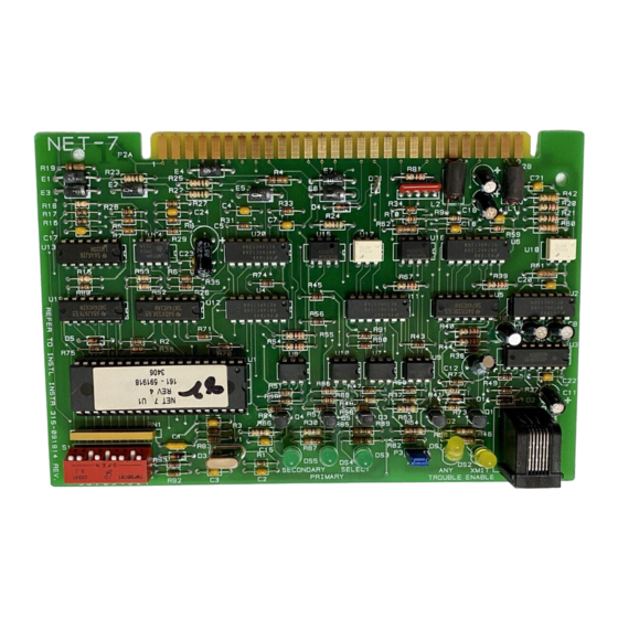
The NET-7 has two yellow LEDs:
1. XMIT ENABLE lights whenever the NET-7
transmits a message.
2. ANY TROUBLE lights when the NET-7 is unable
to communicate to the MMB on either pair.
Three green LEDs on the NET-7 indicate the state
of two communication pairs. The first two LEDs,
PRIMARY and SECONDARY, light whenever the
NET-7 receives a message on that pair. Use these
two LEDs when troubleshooting to determine if a
pair is active. The third green LED, SELECT,
indicates the communication pair currently connected
Siemens Industry, Inc.
Building Technologies Division
Florham Park, NJ
P/N 315-091914-13
to the modules in the enclosure. In normal operation,
the SELECT LED turns on and off every time there is
network activity. If this LED remains in one state
(either on or off), it indicates that one or both of the
pairs is not functional. The SELECT LED lights when
the PRIMARY pair is selected.
The NET-7 can also provide a Style 4 communication
mode. In that configuration all NET-7s must be set to
Style 4. Use P3 on the NET-7 to make this selection.
CAUTION: NET-7s and NET-4s cannot be
combined in the same system.
The NET-7 offers advanced performance over the
NET-4. Each NET-7 determines which modules are
installed in its enclosure and reports this information
to the MMB where it is compared to the CSG-M data
base. That information verifies that the system is
properly installed. The default setting in the MXL has
this feature deactivated. The user can change the
default setting in CSG-M or temporarily change the
setting by selecting the OVERRIDE submenu of the
TEST menu in the MXL. When using the MXL menu,
the change remains in effect until power is removed.
Error checking is available in either Style 4 or Style 7.
All terminals are power limited.
For additional information on the MXL/MXLV System,
refer to the MXL/MXLV Manual, P/N 315-092036.
Siemens Building Technologies, Ltd.
Fire Safety & Security Products
2 Kenview Boulevard
Brampton, Ontario
L6T 5E4 Canada
Advertisement

Related Manuals for Siemens NET-7


Summary of Contents for Siemens NET-7
-
Page 1: Installation Instructions
In that configuration all NET-7s must be set to Style 4. Use P3 on the NET-7 to make this selection. Each NET-7 connected represents one network drop on the MXL System. There can be a maximum of 32 CAUTION: NET-7s and NET-4s cannot be drops. - Page 2 TB4 on the PSR-1 as shown. CAUTION: Do not touch the gold plated 10. Install the NET-7 into P7. Be sure that the board card edge on the NET-7. is firmly seated. 2. Set the address for the NET-7 using switch S1.
- Page 4 TABLE 1 NETWORK ADDRESS PROGRAMMING 8 76 54 32 1 8 7 6 5 4 3 2 1 8 7 6 5 4 3 2 1 8 7 6 5 4 3 2 1 ADDR ADDR ADDR ADDR ILLEGAL OXOOOOOO XOOOOOOO XXOOOOOO ILLEGAL...