Table of Contents
Advertisement
Advertisement
Table of Contents

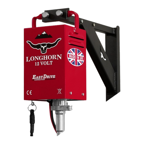
Summary of Contents for HORNER Shearing Longhorn 3.2
-
Page 2: Table Of Contents
INTRODUCTION Introduction These instructions must be read by any person intending to use or service the machine. Purpose of use This equipment is expressly designed and intended for use for the shearing of sheep, goats and animals of the Camelidae family. -
Page 3: Electrical Safety
ELECTRICAL SAFETY Important safety information Battery Safety: • Don’t use a battery that looks damaged or is leaking • Don’t use a machine with damaged battery leads • Don’t smoke or allow naked flames anywhere near the battery • Don’t let any metal objects come in contact with the battery as these could cause a spark and possibly make the battery explode. -
Page 4: Mounting
MOUNTING Secure fixing The machine should be fixed securely when in use: • This prevents damage to the electric flex and avoids electrical hazards • Allows the spring to operate correctly when using a solid drive Mount the machine so that the flexible drive is 20mm clear of the floor or for solid drives, 10mm clear of the floor. -
Page 5: Attaching Flexible Drive
ATTACHING DRIVE Flexible driveshaft Fig. 1 Make sure the EasyDrive clamp is in the open position (Fig. 1) and then push up the outer driveshaft into the base casting of the machine until the top fitting reaches it shoulder stop (Fig. 2). Fig. -
Page 6: Attaching Solid Drive
ATTACHING DRIVE Solid driveshaft Fig. 1 Make sure the EasyDrive clamp is in the open position (Fig. 1) and then push up the long tube and spring into the base casting of the machine until the top fitting reaches it shoulder stop (Fig. -
Page 7: Attaching Handpiece
ATTACHING HANDPIECE For pin drive machines • Hang the machine up and attach the driveshaft • Make sure the machine is turned off • Push the handpiece onto the drive firmly • Rotate clockwise, once you feel the handpiece locate into the bayonet, rotate another full time. -
Page 8: Lubricating Flexible Driveshaft
FLEXI DRIVE LUBRICATION Oiling the driveshaft Frequency: after every 4 hours of use Directions • Remove the handpiece and the driveshaft • Add oil into the top of the driveshaft • Re-fit driveshaft to the machine Greasing the driveshaft Frequency: After every 40 hours of use or annually Directions •... -
Page 9: Lubricating Solid Driveshaft
SOLID DRIVE LUBRICATION Oiling the driveshaft Frequency: After every 4 hours of use Directions • Remove the handpiece and the driveshaft • Add oil into the top of the driveshaft (1) • Add oil into the top of the long tube (2) •... -
Page 10: Troubleshooting
TROUBLESHOOTING Problem Cause Solution Poor battery lead Check connections and connections condition of wires / clips Faulty switch Have switch replaced Motor does not start Damaged relay Have relay replaced Burnt out motor Have motor replaced Motor struggles to start or runs Worn brushes Have brushes replaced slowly... -
Page 11: Wiring Diagram
WIRING DIAGRAM DIODE PULL SWITCH RELAY TERMINAL BLOCK LONGHORN 12V INSTRUCTION MANUAL... -
Page 12: Motor Parts List
MOTOR Parts list Model Drive Speed Motor Rated Voltage Power Consumption 3,200 RPM 12V - 14V 3,500 RPM 12V - 14V Box Cover Insulated Wire, Relay to Switch (1.5mm) Base Plate Insulated Wire, Terminal Block to Relay (4mm) Motor - Model 3.2 (3,200RPM) Insulated Wire, Terminal Block to Switch (1.5mm) Motor - Model 3.5 (3,500RPM) -
Page 13: Motor - Technical Drawing
MOTOR LONGHORN 12V INSTRUCTION MANUAL... -
Page 14: Flexible Driveshaft - Technical Drawing
FLEXI DRIVESHAFT H11-507 Outer 4 H18-020 Bayonet Spring 2A H11-505 Inner (Pin) 5 H49-100 Bayonet End 2B H11-506 Inner (Worm) 6 H49-102 Worm End H11-039 Male Coupling 7 H49-002 Flexi Ferule LONGHORN 12V INSTRUCTION MANUAL... -
Page 15: Solid Driveshaft - Technical Drawing
SOLID DRIVESHAFT EasyDrive Spring H18-002 Coupling H18-003 Lock Nut H18-004 Long Lug Bolt H18-005 Spring H18-006 Long Tube H18-007 Ferule H18-008 Eye Spindle H18-009 Elbow Joint H18-010 Solid Cog 10 H18-011 Elbow Guard 11 H18-012 Joint Cap 12 H18-013 Joint Spring 13 H18-014 Short Lug Bolt 14 H18-015 Short Tube 15 H18-016 Short Gut (Pin) -
Page 16: Technical Data
Manufactured by Horner Shearing Lane Side • West Bradford • Clitheroe • BB7 4QH • United Kingdom...


Need help?
Do you have a question about the Longhorn 3.2 and is the answer not in the manual?
Questions and answers