Table of Contents
Advertisement
Advertisement
Table of Contents

Related Manuals for Balluff BNI EIP-508-005-E002


Summary of Contents for Balluff BNI EIP-508-005-E002
- Page 1 BNI EIP-508-005-E002 EtherNet/IP™ IP69 modules User's Guide...
-
Page 2: Table Of Contents
Module Configuration BNI EIP-508-X05-XXX Module Configuration BNI EIP-507-005-Z040, BNI EIP-527-005-Z040 Module Configuration BNI EIP-508-XXX-XXXX-C06 IO-Link Port Configuration Cycle Settings Validation Settings Parameter Server Upload Flag on the IO-Link Device Configuration via Explicit Messages QuickConnect Rockwell Automation products that are compatible with QuickConnect www.balluff.com... - Page 3 Balluff Network Interface EtherNet/IP™ Example with Rockwell Components PLC Program Fault State Enable/Disable Fault State Fault State Action IO-Link Device Para-meterization Read IO-Link Parameter Write IO-Link Parameter Process Data 7.1. Process Data Inputs Standard Input Data IO-Link Input Data 7.2. Process Data Outputs...
-
Page 4: General
Cross-references indicate where additional information on the topic is located. 1.3. Symbols Note This symbol indicates general notes. Attention! This symbol indicates a security notice which must be observed. 1.4. Abbreviations Balluff Network Interface Standard input port EtherNet/IP™ Electromagnetic compatibility Function ground Standard output port 1.5. Deviating views Product views and illustrations in this manual may differ from the actual product. -
Page 5: Safety
Before working on the device, switch off its power supply. Note In the interest of continuous improvement of the product, Balluff GmbH reserves the right to change the technical data of the product and the content of these instructions at any time without notice. www.balluff.com... -
Page 6: First Steps
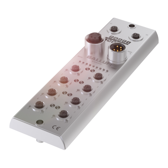
First Steps 3.1. Module Overview Figure – Overview: BNI EIP-508-005-E002 EtherNet/IP™ port 1 Port 10 / 11 Power OUT Pin/port LED: signal status Port 00 / 01 Port 08 / 09 Port 02 / 03 Status LED: communication / module... -
Page 7: Mechanical Connection
Balluff Network Interface EtherNet/IP™ First Steps 3.2. Mechanical The module is secured by means of two M6 screws and two washers. Connection Insulation support is available separately. 3.3. Electrical Connection Power Supply Function Description +24 V Actuator supply 7/8”, male... -
Page 8: Io-Link / I/O Port
For the digital sensor inputs, refer to guideline on inputs EN 61131-2, Type 2. Note The total current of the module must not exceed 9 A. Note Unused I/O ports must be provided with cover caps to comply with degree of protection IP69. Port Port BNI EIP-508-005-E002 IN / OUT / IO-Link www.balluff.com... -
Page 9: Technical Data
Balluff Network Interface EtherNet/IP™ Technical Data 4.1. Dimensions 4.2. Mechanical Data Housing material Stainless steel (V4A) Enclosure rating per IEC 60529 IP 69 (only when plugged-in and threaded-in) Supply voltage 7/8" 4-pin, connector / female Input ports / output ports... -
Page 10: Ethernet
Initial sequence Module has no IP address Green, flashing Module has IP, but no connection established Netw Green Connection established Red, flashing Connection timeout Red-green, flashing Initial sequence Bus clock: 10 Mbps Yellow Bus clock: 100 Mbps Green Data transfer www.balluff.com... -
Page 11: Port
Balluff Network Interface EtherNet/IP™ Technical Data Port Each port has two bicolored LEDs for displaying the I/O statuses. Display Status Description I/O status The status of the input or output pins is 0 Yellow I/O status The status of the input or output pins is 1... -
Page 12: Integration
5.1. Integration in Here you see an example of how the module can be integrated into a Rockwell RS Rockwell RS Logix 5000: Logix 5000 First go offline Right-click Ethernet (on the correct scanner card) Select a new module www.balluff.com... - Page 13 Balluff Network Interface EtherNet/IP™ Integration Then select the general Ethernet module as the ETHERNET module in the communication path Now enter a user-defined tag name to select the Data-SINT general format, enter the IP address of the module and the correct connection parameters.
- Page 14 Integration The new module and corresponding controller tags are generated automatically. Then download the configuration www.balluff.com...
- Page 15 Balluff Network Interface EtherNet/IP™ Integration When the download is done, you can observe and control the tags using the Controller Tags option. Make sure you select the correct tag name, which you configured beforehand. The input, output and configuration data for this is described on the following pages.
-
Page 16: Address Specifications
Configuration of IO-Link port 5 146…169 IO-Link port 6 Configuration of IO-Link port 6 170…193 IO-Link port 7 Configuration of IO-Link port 7 Note The BNI EIP-508-XXX-XXXX-C06 has no configuration data. These are fixed and can not be changed. www.balluff.com... -
Page 17: Module Configuration Bni Eip-507-005-Z040, Bni Eip-527-005-Z040
Balluff Network Interface EtherNet/IP™ Integration Module Configuration Description BNI EIP-502-105- Port function 0x00: Standard I/O 0x01: IO-Link Module Configuration Description BNI EIP-508-X05- Port function 0x00: Standard I/O 0x01: IO-Link Module Configuration Description BNI EIP-507-005- Z040, BNI EIP- Port function 527-005-Z040... -
Page 18: Io-Link Port Configuration
These bits contain a 6-bit multiplier for the calculation of MasterCycleTime or MinCycle Time. Permissible values for the multiplier Time Multiplier 0 to 63. base Bit 6 to 7: Time Base These bits specify the time base for the calculation of MasterCycleTime or MinCycleTime. www.balluff.com... -
Page 19: Validation Settings
Balluff Network Interface EtherNet/IP™ Integration Possible values of MasterCycleTime and MiniCycleTime Time base Time Base Calculation Cycle Time encoding value 0.1 ms Multiplier x Time Base 0.4 ms to 6.3 ms 0.4 ms 6.4 ms + Multiplier x Time Base 6.4 ms to 31.6 ms... -
Page 20: Upload Flag On The Io-Link Device
To enable the upload flag of an IO-Link device, the data value 0x05 must be entered in the index 0x02, subindex 0. (For information about configuration via IO-Link, refer to the "Web Server" chapter under "Device Properties" or the "Configuration via Explicit Messages" chapter under "IO-Link Device Parameterization") www.balluff.com... -
Page 21: Configuration Via Explicit Messages
Balluff Network Interface EtherNet/IP™ Configuration via Explicit Messages QuickConnect The BNI EIP-508-005-E002 module can be launched and connected faster via the QuickConnect function. Enabling QuickConnect automatically takes over all necessary port properties on the module: • Static IP address •... -
Page 22: Rockwell
Configuration via Explicit Messages Rockwell Automation products that are compatible with QuickConnect Source: Allen-Bradley Ethernet/IP QuickConnect Application Technique Page 13 www.balluff.com... - Page 23 Balluff Network Interface EtherNet/IP™ Configuration via Explicit Messages Example with Rockwell Components Source: Allen-Bradley Ethernet/IP QuickConnect Application Technique, Page 12 Please also note the following: • Direct connection between PLC and QuickConnect slave with crossover cable • Slave-to-slave connection using patch cable •...
- Page 24 Configuration via Explicit Messages PLC Program Source: Allen-Bradley Ethernet/IP QuickConnect Application Technique, Page 29 www.balluff.com...
- Page 25 Balluff Network Interface EtherNet/IP™ Configuration via Explicit Messages Source: Allen-Bradley Ethernet/IP QuickConnect Application Technique, Page 30 www.balluff.com...
- Page 26 Configuration via Explicit Messages Source: Allen-Bradley Ethernet/IP QuickConnect Application Technique, Page 31 www.balluff.com...
- Page 27 Balluff Network Interface EtherNet/IP™ Configuration via Explicit Messages Source: Allen-Bradley Ethernet/IP QuickConnect Application Technique, Page 32 Fault State A safe state that the port is to take on in the case of a loss of bus communication can be predefined for each output on the port pins.
- Page 28 Source Length must correspond to at least the read parameters, but a larger value can also be entered. (In this example, 100 bytes) As the Source Element (Write) and as the Destination Element (Read), create one SINT[100] array each and select the first line[0]. www.balluff.com...
- Page 29 Balluff Network Interface EtherNet/IP™ Configuration via Explicit Messages In the Source Element Array (Write), enter which index is to be read. In this example, this is index 0x4E. Destination Array (Read) shows the read-out value. In case of a configuration error, the error code is likewise displayed there.
- Page 30 In the "Communication" window, you likewise have to select the Ethernet module on which the configuration is to take place. Note The explicit messages functions are implemented in accordance with the Volume 1: Common Industrial Protocol Specification and Volume 2: Ethernet/IP Adaption of CIP. www.balluff.com...
- Page 31 Balluff Network Interface EtherNet/IP™ Process Data 7.1. Process Data The input data size is 392 bytes. Take a look at the tables below for the allocation of the Inputs process data inputs. BNI EIP-508-005-E002 Byte Module part Description 0…7 Standard I/O ports Process data inputs at the standard inputs 8…55...
- Page 32 Event 2 Type: Event code low 0: Reserved Mode Type 1: Notification Event code high Event 3 2: Warning Event code low 3: Error … The data of the other IO-Link ports are structured identically and described in the following. www.balluff.com...
- Page 33 Balluff Network Interface EtherNet/IP™ Process Data 7.2. Process Data The output data size is 262 bytes. Take a look at the tables below for the allocation of the Outputs process data outputs. BNI EIP-508-005-E002 Byte Module part Description 0…5 Standard I/O ports Process data outputs at the standard inputs 6…37...
- Page 34 For open a connection with the web server, enter the IP address of the module in the address line of the browser. The homepage then appears with the essential device information. www.balluff.com...
- Page 35 The navigation bar is located in the upper area of the window, which allows you to switch between the various dialogs of the web interface. To do this click on the corresponding icon. When the "Info" tab is selected the following overview appears: The "BALLUFF" logo at upper right links to the international Balluff homepage. www.balluff.com...
- Page 36 Note For security reasons the fieldbus module shows only one login at a time with configuration access. Reading (without logging in) is however possible from multiple PCs at the same time on the fieldbus module. www.balluff.com...
- Page 37 Balluff Network Interface EtherNet/IP™ Web Server 8.4. "Home" dialog Under "Home" you are given the essential information about the fieldbus itself and its network activity. You are also shown whether the configuration block was enabled by the controller (PLC). Information is also shown about the current process data and the status of the module via the corresponding LEDs.
- Page 38 Web Server PNT: EIP: www.balluff.com...
- Page 39 Balluff Network Interface EtherNet/IP™ Web Server 8.5. "Ports" dialog The "Ports" dialog displays information and process data for the connected IO-Link devices. Select the desired IO-Link Port in the image of the fieldbus module on the right side to see the device data.
- Page 40 Thus in the following screenshot not only are the input data of the distance sensor displayed as a hex number, but also interpreted and labeled under "Input". Since the sensor has no parameters, none are displayed. Dialog "Ports“: IODD interpretation and device image www.balluff.com...
- Page 41 Web Server If the IODD of the IO-Link device on the currently selected port has parameters, these are shown in table format (see following screenshot). In this example the parameters for the Balluff Smart Light are shown. The Smart Light is a signal light which can be used in three different modes. These modes can be set using an IO-Link parameter.
- Page 42 Using the "Delete" button you can delete IODDs and device images from the fieldbus when needed. Note Before selecting the IODD it must be renamed on the PC to the file name which is shown in the table in the "IODD Filename" column! www.balluff.com...
- Page 43 Balluff Network Interface EtherNet/IP™ Web Server 8.7. "Config" dialog The configuration page enables configuration of the module. You can change both the module information texts and the port configuration. The "Set Ports" action is not permanently stored in the device and is lost after the next reboot or reset.
- Page 44 The "Reboot" button reboots the device as if the power to the module had been turned off and on again. Clicking on "Factory Reset" deletes the configuration and log files saved in the device and then performs a reboot, so that the device is restored to the default factory configuration as on delivery. www.balluff.com...
- Page 45 Balluff Network Interface EtherNet/IP™ Web Server 8.8. "Log" dialog This dialog provides general service information about the device as well as a logging function. The upper table (see screenshot below) contains important information for all service inquiries. Note If you have a detailed question about a specific situation, send us a screenshot of this Web site or print the site as a PDF.
- Page 46 After a reset, reboot or loss of power the time begins to run again from the year 2000. Clicking on "Update Log” refreshes the display, and "Clear Log” deletes all entries. The log entries are stored in a ring buffer. www.balluff.com...
- Page 47 Appendix 9.1. Order number BNI EIP-508-005-E002 Balluff Network Interface Ethernet IP Functions 508 = IP 69 IO-Link master module, 8 IO-Link ports Variants 005 = 2-Port-Switch Mechanical Version E002 = Stainless steel housing V4A Data transmission: 2 x M12x1 internal thread Power supply: 7/8"...
- Page 48 Balluff GmbH Schurwaldstrasse 9 D-73765 Neuhausen a.d.F. Germany Tel. +49 7158 173-0 Fax +49 7158 5010 www.balluff.com balluff@balluff.de...
Need help?
Do you have a question about the BNI EIP-508-005-E002 and is the answer not in the manual?
Questions and answers