Advertisement
Quick Links
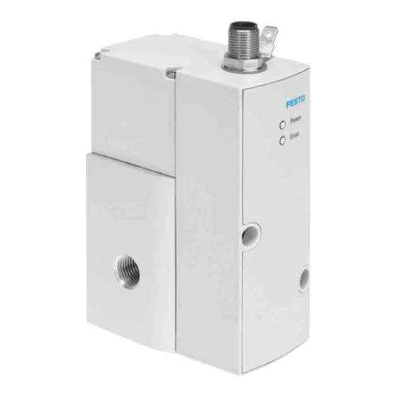
Proportional pressure regulator valve
VPPM-...-LK-...
Operating instructions
(Translation of the original instructions)
For all available product documentation è www.festo.com/pk
Proportional pressure regulator valve
®
IO-Link
is a registered trademark of the trademark holder in certain countries.
1
Application and function
The VPPM is intended for controlling a pressure
proportional to a specified setpoint value (input
word). A built-in pressure sensor records the
pressure at the working port and compares this
value with the setpoint value. If there are devi
ations between the actual value and the set
point value, the control valve is actuated until
the outlet pressure reaches the setpoint value.
2
Characteristics in the type code
Type code
1
VPPM - 6L -
L
-
1
-
G18
2
3
Item
Characteristics
1
Nominal width in [mm]
Valve type
2
Dynamic response class
3
Valve function
4
Pneumatic connection
– Flange/sub-base
– ISO thread
5
Control ranges
– Lower pressure value
– Upper pressure value
6
– Setpoint specification
7
Accuracy
Fig. 2
3
Requirements for product use
• Installation and commissioning is to be carried out only by qualified personnel,
in accordance with the documentation.
• Take into consideration the ambient conditions at the location of use.
• All applicable national and international regulations must be complied with.
Festo AG & Co. KG
Ruiter Straße 82
73734 Esslingen
Germany
+49 711 347-0
www.festo.com
8086184
2018-03b
[8086186]
. . . . . . . . . . . . . . . . . . . . . . . . . . . . .
Fig. 1
4
5
6
-
0L6H
-
LK
-
S1
7
Significance
6, 8, 12
F (flange), L (sleeve)
L (Low)
1 (3-way pressure regulator, normally
closed)
F6 (NW 6 mm), F8 (NW 8 mm)
G18 (x"), G14 (¼"), G12 (½")
0L (0 bar)
2H (2 bar), 6H (6 bar), 10H (10 bar)
IO-Link-specific
S1 (1 %)
• Use the product in its original status, without any unauthorised product
modifications.
• Ensure that the compressed air is properly prepared (è Technical data).
• Pressurize your entire system slowly. There will then be no uncontrolled
movements.
Range of application and certifications
In combination with the UL mark on the product, the information included in this
section is also applicable for compliance with the certification requirements of
Underwriters Laboratories Inc. (UL) for USA and Canada.
UL approval information
Product category code
File number
Standards taken into account
UL identification
Fig. 3
The product must be powered by a power source that fulfills the requirements of
an energy-limited circuit in accordance with IEC/EN/UL/CSA 61010-1 or a power
source with limited power (LPS)in accordance with IEC/EN/UL/CSA 60950-1 or
IEC/EN/UL/CSA 62368-1 or a Class 2 circuit in accordance with NEC or CEC.
3.1 Connections and mounting holes (in-line valve)
English
3
1
Electr. connecting plug (5-pin)
2
Air (2), pressure output
3
Through holes for mounting. For
size ½" in the manifold block
Fig. 4
4
Installation
4.1 Mechanical
• Make sure there is sufficient space for the connecting cable and tubing connec
tions. In this way you will prevent the cable and tubes from being bent.
• Place the VPPM as close to the consumer as possible. This leads to improved
control precision and shorter response times.
Wall mounting
• Fasten the in-line valve of size x" and ¼"
at the intended position with two M4 screws.
If necessary, use bracket type VAME-P1-A
(è Fig. 5) to do this. When using the bracket,
the VPPM may only be loaded statically.
• Fasten the in-line valve of size ½" at the
intended position with two M5 screws
(tightening torque 2.0 Nm).
• Mount the flange valve of size x" and ¼"
onto the manifold rail VEABM-P1-SF-G18...
(tightening torque approx. 1.5 Nm). Fasten
the manifold rail at the intended position
with two M6 screws.
QUYX, QUYX7
E322346
UL 610101, CAN/CSAC22.2 No. 610101
1
2
5
4
4
Compressed air (1), supply port
5
Exhaust (3)
Fig. 5
3
Advertisement

Related Manuals for Festo VPPM-...-LK Series


Summary of Contents for Festo VPPM-...-LK Series
- Page 1 IEC/EN/UL/CSA 62368-1 or a Class 2 circuit in accordance with NEC or CEC. 3.1 Connections and mounting holes (in-line valve) For all available product documentation è www.festo.com/pk Proportional pressure regulator valve ......
- Page 2 • On the device is a 5-pin plug, M12, port type A. Upper limit value ≤ lower limit value • Use the pre-assembled cable with socket from Festo (accessories Upper limit value < 0 or > control range (è Fig. 17) è...
- Page 3 Valve parameter: ID Valve parameter: Condition counter solenoid coil Parameter no. Parameter no. 8...11 Condition counter limit Description Provides valve identification for I-Port Manual A limit value for a counter (condition counter) can be set for the internal solenoid coil in the pilot control of the pressure regulator. A message is Values In-line valve Flanged valve...
- Page 4 Lights up Data rate Suppor ts all IO-Link data transmission rates Communication active Flashes 1 Hz (9:1) See declaration of conformity è www.festo.com Electromagnetic Compatibility è Fig. 23 Error / diagnostics – Emitted interference CE conformity for industrial installations fulfilled...
Need help?
Do you have a question about the VPPM-...-LK Series and is the answer not in the manual?
Questions and answers