Table of Contents
Advertisement
Quick Links
Advertisement
Table of Contents

Summary of Contents for WIDMER TIME RECORDER CO., INC. RS
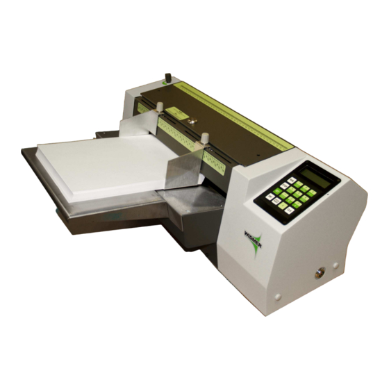
- Page 1 WIDMER ROTARY STAMP OPERATIONS MANUAL WIDMER TIME RECORDER CO., INC. 228 Park Street 27 Park Place Hackensack, NJ 07601 New York, NY 10007 Phone: 201 489-3810 (800) 424-4459 Phone: 212 227-0405 Fax: 201 489-3478 Fax: 212 227-0526 2008 Dec09 Revision...
-
Page 3: Table Of Contents
Installing the Die on the Drum ……………………………………………………...-8- Setting the Paper Guides and Feathering the Documents …………………...…-8- RS Gap Setting Instructions ………………………………………………………..-9- Setting the Print Position and Paper Length fir Signatures …………………..-10- Setting the Print Position and Paper Length for Text and Seals ……………...-12- Date and Manual Set Numbers …………………………………………………..-13-... -
Page 4: Specifications
OPERATING INSTRUCTIONS FOR RS MODELS Please check the current voltage and cycles on the specifications plate at the rear of the machine to be certain that these conform with the power source you intend using. Please record the serial number, model number, and key numbers for future refer-... -
Page 5: Overview
Additionally the model RS-ETV will also emboss a seal into you document. As the RS is a bottom feed unit there is no change in the order of the documents as they are processed by the machine. The operator can also add documents to the hopper as the job progresses which increases the speed and efficiency of the operation. -
Page 8: Installation
INSTALLATION Installing the die on the drum Adjustable spring clips hold the plate to the drum. The plate snaps on the drum in either direction so a page may be fed from either the top or the bottom edge of the sheet depending on the requirements of the job. -
Page 9: Rs Gap Setting Instructions
RS Gap Setting Instruction Knob ‘A’ opens and closes the space (or gap) between stone roller ‘B’ and the stripper roller ‘C’. To set this gap correctly, turn on machine and hit RUN. While holding a piece of paper in between stone roller ‘B’ and stripper roller ‘C’, turn knob ‘A’ until you feel a drag on the paper as the machine tries to draw the paper into itself. -
Page 10: Setting The Print Position And Paper Length Fir Signatures
In order for the RS to print in the proper place on the document, two pieces of information are required; the print position and the paper length. The following are instructions for finding and setting the print position and paper length for machines with signature and text dies. - Page 11 Measure the length of the document from the top of the document to the bottom. Starting this measurement at the 0 indication on the scale. This value is the Paper Length. The paper length is keyed in similarly. Press ‘SET’ then press ‘PAPER LENGTH’...
-
Page 12: Setting The Print Position And Paper Length For Text And Seals
Measure the distance from the Top Of Document Here line, using the scale on the RS’s top cover from the leading edge of the document to where you want the to edge of the text or seal to begin. This value is the Print Position. -
Page 13: Date And Manual Set Numbers
Date & Manual Set Numbers RS date and/or number wheels setting method will vary slightly from model to model. The highest point on the document that the date can appear is 3/4” measured to signature location. -
Page 14: Impression Adjustment
Impression Adjustment 1. Adjusting screws for the ink roller are located on both sides. Counter clockwise lowers the roller and darkens the impression. Clockwise raises the roller and lightens the impression. 2. Ink roller(s) shaft snaps in here. 3. Impression roller adjustments (one on the left and one on the right side of the machine) should be kept even. -
Page 15: Programming
PROGRAMMING Key Pad Operations RUN starts the printing process. If the machine does not sense a document for 30 seconds it will stop itself as if the operator pressed STOP. To have the machine continue from where it left off push RUN again. STOP will stop the printing process. - Page 16 As the operator scrolls through the presets the machines display will feed information back to user. The information consists of all pertinent data regarding that particular preset. Where “1” is the preset memory number. “P LNTH 150” states the paper length is 150 units long, i.e. see the scale on the machine.
-
Page 17: Programming Keys
25 documents. The user can select to count up to 25, then after pressing “run”, the RS will resume the counting and stop after that group’s 25th document. The RS’s display will show the total number of documents processed. Or the RS can count down to zero from 25. - Page 18 When in count up mode the counter will continuously increment as impressions are made. The RS runs off “batches” of the preset number of sheets each time RUN is pressed. For more information see the example at the end of this section.
-
Page 19: Non-Reset Counter
As the name implies this is a non- resettable feature. To view the total number of documents run through the RS during its life time press SET and then press NON-RESET COUNTER the machine will then display: Press any key to return to the operations screen. -
Page 20: Remove Imprint Die
Preset programs The RS has the ability to memorize the settings for up to 9 different jobs. These presets include all the information, including options, necessary to run a particular job. Use this function to set and lock into the machines memory information regarding various documents that may be frequently imprinted for easy retrieval at a later time. -
Page 21: Keypad Layout
This will take the current settings of the machine and store them in a preset memory (#1-9) for usage at some later time when the user wants to Utilize the Preset. For example if the user wants to save the machines current setting to PRESET #3, pressing 3 would yield: Should the user press ENTer the current settings would then be saved to PRESET #3. -
Page 22: Maintenance
MAINTENANCE Caution / Warning Like most equipment, when operating and during set up please remember to keep hands, loose clothing, hair, jewelry and ties away from all moving parts. Service should be provide only by a Factory Authorized Service Center Representative.
Need help?
Do you have a question about the RS and is the answer not in the manual?
Questions and answers