Advertisement
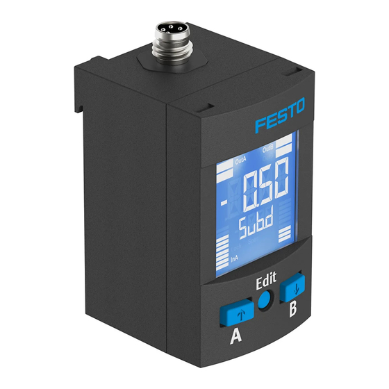
Pressure sensor SPAU
Operating instructions
Original: de
Pressure sensor SPAU
. . . . . . . . . . . . . . . . . . . . . . . . . . . . . . . . . . . . . . . . . .
1
Product description
The operating instructions describe the entire function range. The function range is
limited, depending on the product variant.
Note
You can find detailed specifications for the product, the device description file
(IODD) with a description of the IO-Link parameters and the declaration of
conformity at: è www.festo.com.
1.1 Overview
Display variant without front panel mounting
1
6
5
4
1
Display
2
Pneumatic port
3
Electrical connection
1) Representation of other variants can deviate
from this.
Fig. 1
1.2 Characteristics
Characteristic
Code
Type
SPAU
Pressure
-B2, -B11, -P025, -P05, -P1, -P2,
measuring range
-P6, -P10, -P12, -P16, -V025,
-V05, -V1
Supply port
R
Type of mounting
-T
-H
-W
-A
-F
Festo AG & Co. KG
Postfach
73726 Esslingen
Germany
+49 711 347-0
www.festo.com
8001199
1410NH
[8041211]
English
1)
2
3
4
B key
5
Edit button
6
A key
Specification
Pressure sensor
è Technical data
Relative pressure
Threaded mounting
H-rail mounting
Wall mounting
Mounting bracket
Front panel mounting
Characteristic
Code
Pneumatic port
-G18, -R18, N18, -R14, -M5, -M7
-Q4,-Q6,-T532
Thread type
M
F
Outlet direction
D
Display
-L
Electrical output 1 -PNLK
-LK
Electrical output 2 -PNVBA
-V
-B
-A
Electrical
-M8
connection
-M12
Electrical outlet
direction
D
U
Electrical
accessories
+2.5A
+2.5S
+5A
+5S
Protective
devices
G
Certificate
T
Fig. 2
2
Function and application
The pressure sensor SPAU is intended for monitoring pressure in the piping. The
sensor converts pneumatic pressure values (relative pressure) into electrical sig
nals, which can be used for control or regulating functions. Measurements are
carried out using a piezoresistive sensor element with a following electronic evalu
ation unit. Interfacing to the higher-level system is provided by 1 or 2 switching
outputs, an analogue output and/or an IO-Link interface.
The switching outputs can be configured for monitoring of a threshold value, a
pressure range or a differential pressure. For each output, PNP or NPN and nor
mally open (NO) or normally closed (NC) can optionally be set. Via the IO-Link inter
face, process values can be read out and parameters changed and transmitted to
additional devices.
2.1 Operating statuses
Operating status Function
RUN mode
– Initial status after switching on the operating voltage
– Display of the current measured value
SHOW mode
– Display of the current settings
EDIT mode
– Setting or modification of parameters
TEACH mode
– Acceptance of the current measured value to determine switching points
Fig. 3
2.2 Switching functions
Threshold value comparator for monitoring of a pressure threshold
Function
NO (normally open)
Switching function:
Out
– 1 Switching point (SP)
1
TEACH mode:
– 2 teach-in points (TP1, TP2)
0
– SP = ½ (TP1+TP2)
Fig. 4
Window comparator for monitoring of a pressure range
Function
NO (normally open)
Switching function:
Out
– 2 Switching points (SP.Lo, SP.Hi)
1
1)
TEACH mode
:
– 2 teach-in points (TP1, TP2)
0
– TP1 = SP.Lo, TP2 = SP.Hi
1) SP.Lo = smaller pressure/vacuum value, SP.Hi = larger pressure/vacuum value, dependent on the
Teach sequence
Fig. 5
Specification
Thread Gx, Rx, NPTx, R¼, M5, M7
Plug connector 4 mm, 6 mm, Â
None
Male thread
Female thread
Rear
Underneath
None
LCD, backlit
Switching output PNP / NPN / IO-Link
IO-Link
PNP / NPN / 0...10 V / 1...5 V / 4...20 mA
0...10 V
1...5 V
4...20 mA
M8 plug
Plug M12, A-coded
Rear
Underneath
On top
None
Angled socket, 2.5 m cable
Straight socket, 2.5 m cable
Angled socket, 5 m cable
Straight socket, 5 m cable
None
Safety guard
None
Test report
NC (normally closed)
Out
HY
HY
1
0
p
SP
SP
TP1
TP2
TP1
NC (normally closed)
Out
HY
HY
HY
1
0
p
TP1=SP.Lo TP2=SP.Hi
TP1=SP.Lo TP2=SP.Hi
p
TP2
HY
p
Advertisement
Table of Contents

Related Manuals for Festo SPAU Series

Summary of Contents for Festo SPAU Series
- Page 1 Thread type None Male thread Female thread Outlet direction Rear Underneath Display None Festo AG & Co. KG LCD, backlit Postfach Electrical output 1 -PNLK Switching output PNP / NPN / IO-Link 73726 Esslingen IO-Link Germany Electrical output 2 -PNVBA PNP / NPN / 0…10 V / 1…5 V / 4…20 mA...
-
Page 2: Installation
• Remove all transport packaging. The material used in the packaging has been è Fig. 29 specifically chosen for its recyclability. • Accessories è www.festo.com/catalogue. Range of applications and certifications In combination with the UL mark on the product, the information included in this max. - Page 3 4.2 Electric Example for LCD display Significance Menu Submenu Warning Measured value indicator and unit in the RUN mode [– 0.53] [bar] Measured value indicator (here negative value) and unit Use only power sources which guarantee reliable electrical isolation of the oper Menu and submenu for the switching outputs (OutA and OutB) ating voltage in accordance with IEC/EN 60204-1.
- Page 4 Switching output OutB or analogue output OutD Set auto difference monitoring d_I¯I_ • Press B key. 1. Press the Edit button briefly. è The first parameter set is displayed. [Fctn] at OutB or [In.Hi] at OutD è [Edit] appears. [OutA] flashes. flashes.
-
Page 5: Menu Structure
5.7 Menu structure Fig. 23 shows the complete menu structure. Some menu options or setting values are not applicable, depending on the selected switching function. Measured value indicator (RUN mode) OutA OutB OutD Spec Edit Edit Edit Edit ANLG MENU _|¯... -
Page 6: Technical Data
Capacitive load maximum DC [nF] Process data content 2 bit BDC (Pressure monitoring) Voltage drop Max. 1.6 14 bit PDV (Pressure measured value) è www.festo.com/sp Pull-down/pull-up resistor PNP: integrated; NPN: not integrated IODD, IO-Link device description Inductive protective circuit On hand Fig. 28 Analogue output Output characteristic curve initial value …...
Need help?
Do you have a question about the SPAU Series and is the answer not in the manual?
Questions and answers