Welch Allyn 5002 Service Manual
Masted scales
Hide thumbs
Also See for 5002:
- Service manual (136 pages) ,
- Directions for use manual (28 pages) ,
- Installation instructions (2 pages)

Subscribe to Our Youtube Channel
Related Manuals for Welch Allyn 5002


Summary of Contents for Welch Allyn 5002
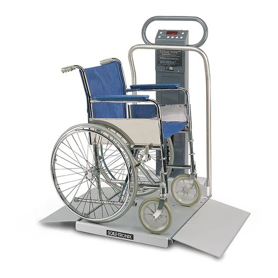
- Page 1 Welch Allyn Masted Scales Service Manual Model 5002 Mobile Stand-On Scale Model 5122 Stand-On Scale Model 5702 Mobile Bariatric Scale Model 6002 Wheelchair Scales Model 6702/SP/W Mobile Bariatric Scale...
- Page 2 © 2016 Welch Allyn. All rights are reserved. To support the intended use of the product described in this publication, the purchaser of the product is permitted to copy this publication, for internal distribution only, from the media provided by Welch Allyn. No other use, reproduction, or distribution of this publication, or any part of it, is permitted without written permission from Welch Allyn.
-
Page 3: Table Of Contents
Calibration of Scale ..........................23 Calibration Procedure ..........................24 Masted Scales Disassembling Guide ......................26 Required tools: ............................26 5002, 6002, 6702, 6702SP, 6702W MAST Disassembling ............... 27 5002, 6002, 6702, 6702SP, 6702W Disassembling ................. 40 5122 Disassembling ..........................51 Troubleshooting ............................59 Scale Troubleshooting .......................... -
Page 4: Scale Setup
6702/6702W/6702SP Base Components ....................72 6702/6702W Base Components ......................72 6702SP Base Components ........................73 5122 Scale Components .......................... 74 MAST Components for 5002, 5702, 6002, 6702 ..................75 Options ..............................75 Schematics & Part Diagrams ........................76 Scale setup You can customize the scale to best suit your needs. - Page 5 RECALL rECALL* This option allows you to turn button functionality. rS-232 Detailed instructions for this feature are available from Welch Allyn. Go to http://www.welchallyn.com/en/other/contact-us.html to find your local representative. OutPut* This option displays the current data port output option. Detailed instructions for this feature are available from Welch Allyn.
-
Page 6: Enter Advanced Service Mode
Off: No parity, 8 data bits Odd: Odd parity, 7 data bits EuEn: Even parity, 7 data bits StPbit* This option allows you to change the stop bits between the following options: 1 bit: One stop at the end of a word 2 bits: Two stops at the end of a word rts.cts* This option allows you to turn On or Off the handshaking hardware for serial transmissions. -
Page 7: Support Services
For information on any of these services, go to www.welchallyn.com/en/servicesupport.html. Warranty Welch Allyn will warranty the weight scale to be free of defects in material and workmanship and to perform in accordance with manufacturer specifications for the period of one year from the date of retail purchase. -
Page 8: Repairs
Qualified service personnel or a Welch Allyn Service Center should repair products out of warranty. If you are advised to return a product to Welch Allyn for repair or routine maintenance, schedule the repair with the service center nearest you. -
Page 9: Warranty Service
Welch Allyn Product Service Centers and Authorized Service Providers support non-warranty repairs. Contact any Welch Allyn regional service center for pricing and service options. Welch Allyn offers modular repair parts for sale to support non-warranty service. This service must be performed only by qualified end-user biomedical/clinical engineers. - Page 10 READOUT ELECTRONICS The Welch Allyn second generation scales employ the model 23005 computer instrument board and the 22DSDP display board. NOTE: Different revision levels of these boards may be incorporated in your scale depending on its manufacturing date.
- Page 11 ANALOG-TO-DIGITAL (A/D) CONVERSION Integrated circuit U6 is the analog-to-digital converter. Included on this integrated circuit are auto-zero functions, auto-polarity, and the digital and analog functions necessary to perform dual slope integration conversion to 20,000 counts (4-1/2 digits). The weight signal voltage is applied to the analog input (pin 10) of U6. A reference voltage for the conversions is applied to pin 2 of U6.
- Page 12 POWER SWITCHING, VOLTAGE REGULATION AND SUPPORT CIRCUITRY Depending upon their configuration, WELCH ALLYN second generation scales may contain disposable primary cells. (Note that some models may be specially ordered to utilize a different power supply than is normally provided; refer to the technical description that best matches the particular scale.) Additional circuitry is included to switch the...
- Page 13 seconds later U11 will time-out and cause the circuit power to switch off. The model 5102 has a jumper added at location J7; this causes U11 to reset U10 in the event of a hardware/software failure. Resistors R1, R2, R3, R5 and R14 are included for proper circuit biasing. Capacitor C6 is used as an output filter. VOLTAGE REGULATION Voltage regulators VR1 and VR2 render regulated sources of +5 Volts DC for operation of the analog (VAA) and digital (VCC) circuits, respectively.
- Page 14 (microcomputer input lines P1.0 through P1.6). The microcomputer also continually scans the keyboard (using U7) looking for closed switches. If a key press is sensed, the microcomputer executes whatever action is called for in its program. After processing the A/D data, the microcomputer assembles it for viewing and transfers it to the front panel display.
-
Page 15: Printer General Description
DISPLAY BOARD Presentation of the weight information is performed by the model 700027W display board. It incorporates LED (light-emitting diode) digits and annunciators to provide a clear, bright, easy-to-read display. The weight value is displayed on six, 0.43” high common cathode digits. These are driven in a multiplexed fashion (one digit on at a time) by LED driver U1. - Page 16 Printing may occur after the patient has left the scale. To print the previous patient's weight, press the "RE CALL" pushbutton followed by the "PRINT" pushbutton. The "PRIOR WEIGHT" annunciator will flash, and the scale's readout will display the previous patient's weight for a short time while the printing continues. The scale will not automatically shut-off until the printing is completed.
- Page 17 PRINTER INTERFACE ASSEMBLY The printer interface assembly is used to control the printer mechanism. It contains all the circuitry needed to interface to the printer mechanism, scale’s electronics, and battery/power supply. For technical explanation purposes it can be divided up into the following sections: 1.) Printer voltage regulation 2.) Microcontroller &...
- Page 18 Reset supervisor U205 is provided to initialize microcontroller U202 on power up. U205 measures the circuit power supply and keeps U202’s reset line high until the proper operating voltage has been reached. C212 determines the width of U205’s reset pulse. R218 keeps U205’s reset input biased high until pulled low for in circuit programming.
- Page 19 Resistors contained in RN201 provide pull-up bias on the various logic interface lines to insure a fast transition. PRINTER INTERFACE TO STEPPER MOTOR The printer mechanism contains a stepper motor to advance the paper during printing and paper feed. The stepper motor is driven by a separate IC designed for that purpose, U203, and is connected to lines OUT1, OUT2, OUT3, and OUT4.
-
Page 20: Maintenance Of Scales
A snap action switch is incorporated within the printer mechanism to determine whether the thermal print head is open for paper insertion or closed for printing. Resistor R206 is included for circuit protection. A section of S202 parallels this switch so that mechanisms not equipped with this switch will operate properly. PRINTER DIP SWITCH OPTIONS An 8-position dip switch is included to allow troubleshooting and some adjustments to operating parameters. -
Page 21: Battery Replacement
4. Replace or repair as necessary. 5. If equipped, inspect the AC line cord for abrasions or other signs of wear. 6. Do not expose the scale to excessive water or moisture. 7. Do not store the scale where heavy objects can be placed on it. Replace the batteries annually or as required. - Page 22 5. Insert the paper through the paper guide slot, and make sure it goes under and around the black roller bar. 6. Pull the paper under the print head lever and push the green knob down to push the print head lever down. 7.
-
Page 23: Calibration Of Scale
Traction or physical therapy weights are NOT acceptable since their actual weight can often be in error as much as +/-10%. Calibration weights may be purchased from WELCH ALLYN or a local scale dealer. An alternative to calibration weights is the weight comparison method. This requires a known accurate, calibrated... -
Page 24: Calibration Procedure
TEST CALIBRATION WEIGHTS ARE AVAILABLE FROM WELCH ALLYN. THREE (3) 25 KILOGRAM TEST WEIGHTS ARE RECOMMENDED. ORDER PART NO. 20021W. (25 KG TEST WEIGHTS) Large changes in calibration often indicate a damaged load cell or faulty readout component. It is generally recommended that if calibration is necessary for your scale it should be returned to the factory. - Page 25 DATA OUTPUT (RS232) DETAILS For detailed help and information regarding the data output capabilities, contact Welch Allyn. RS232 data output has been made a standard feature on many of our scales in 2013. Existing scales can be easily modified to provide...
-
Page 26: Masted Scales Disassembling Guide
Masted Scales Disassembling Guide Required tools: 5/32” Allen wrench Small slotted screwdriver 1/8” Allen wrench Small Philips screwdriver 9/16” Open end wrench #1 Phillip screwdriver ½” Open end wrench ¼” Ratchet driver with extension 5/16” socket 10 mm nut driver 10 mm socket 5 mm nut driver 11 mm socket... -
Page 27: Sp, 6702W Mast Disassembling
5002, 6002, 6702, 6702SP, 6702W MAST Disassembling MAST with AC Power Option: 1. Mast with AC power option only: Use a 1/8” Allen wrench to remove the two screws on the power access door 2. Remove the power cord from the IEC... - Page 28 3. Disconnect the wiring harness 4. Disconnect the power jack 5. Disconnect J1...
- Page 29 6. Use a 10 mm socket to remove the nut on the access panel 7. Use a #1 Phillip screwdriver to remove the screw on the access panel so the power supply can be removed...
- Page 30 MAST with Battery Option: 1. Mast with battery operated option only: Use a #1 Phillip screwdriver to remove the two screws on the battery access door to remove the door 2. Remove batteries 3. Use a #1 Phillip screwdriver to remove the four screws on the battery holder assembly...
- Page 31 4. Separate the J1 Power cord (in black and red) from the gray cable so the battery holder can be removed completely MAST with Printer Option: Mast with a printer option only: Use a 5/16” socket to remove the nuts on the printer assembly panel...
- Page 32 2. Disconnect J15 3. Disconnect the wire harness 4. Disconnect J201 and J202...
- Page 33 5. Use a #1 Phillip screwdriver to remove the screws 6. Disconnect J204, J207, J206, J203 7. Use a #1 Phillip screwdriver to remove the screw on the printer access door...
- Page 34 8. Use a 5/16” socket to remove the nuts on the printer mechanism assembly four screws...
- Page 35 MAST with RS232 Option: 1. RS 232 port disassembly: Use a 1/8” Allen wrench to remove the two screws on the RS232 port access door 2. Disconnect J14...
- Page 36 MAST Readout Disassembly: 1. Readout Disassembly: Use a 1/8” Allen wrench to remove the two screws on the readout panel cover. Remove the cover by lifting it up to reveal the readout board 2. Disconnect J6 3. Disconnect J4...
- Page 37 4. Lift the black clamp to remove J4 5. Disconnect J1 6. Use a #1 Phillip screwdriver to remove the screws on each corner of the board...
- Page 38 7. To remove the switch assembly, use a #1 Phillip screwdriver to remove the four screws 8. Unplug the blue-ribbon cable MAST Removal: 1. Mast Removal: Use a 3/8” Allen wrench to remove the two screws on the cover panel...
- Page 39 2. Use a small screwdriver to remove the two screws on the blue connector 3. Use a 9/16” wrench to remove the two hex bolts on the mast’s bottom 4. Pull the mast from the base...
-
Page 40: Sp, 6702W Disassembling
5002, 6002, 6702, 6702SP, 6702W Disassembling 5002 Top Plate Disassembly: 1. 5002 Top Plate Disassembly: Use a 5/32” Allen wrench to remove the three screws on each handrail (if equipped) 2. Remove the dust cover 3. Use a 1/8” Allen wrench to loosen the... - Page 41 5702 Top Plate Disassembly: 1. 5702 Top Plate Disassembly: Use a 5/32” Allen wrench to remove the three screws on each handrail (if equipped) and the screws on the slider deck top cover 2. Remove the dust cover 3. Use a 1/8” Allen wrench to loosen the four screws on the top plate NOTE: When reassembling the top plate, remember to turn the screws back 90...
- Page 42 6002 Top Plate Disassembly: 1. 6002 Top Plate Disassembly: Use a 1/8” Allen wrench to remove the 7 screws on each bracket 2. Use a 1/8” Allen wrench to remove the additional 7 screws on the side of each bracket 3.
- Page 43 4. Use a 1/8” Allen wrench to remove the four screws on the top plate NOTE: When reassembling the top plate, remember to turn the screws back 90 the deck can float. 6702W, 6702, 6702SP Top Plate Disassembly: 1. 6702W, 6702, 6702SP Top Plate Disassembly only: Use a 1/8”...
- Page 44 3. Use a 5/32” Allen wrench to remove the screws on the top plate 10 (6702W & 6702SP) or 14 (6702) 5002, 5702, 6002 Base Disassembly: 1. 5002, 5702, 6002 Base Disassembly only: Use a 10 mm socket to remove the two nuts on each load cell...
- Page 45 3. Disconnect the wire harnesses from the junction board 4. Use a #1 Phillip screwdriver to remove the screws on the junction board 5. Use a 10 mm socket to remove the screw on the two cable clamps...
- Page 46 6. Use a 5/32” Allen wrench to remove the four screws on the bottom pan and the bottom pan can be removed 7. Use a ½” wrench to remove the nuts on the wheel’s screw. Remove the wheel...
- Page 47 8. Use a ½” wrench to remove the remaining nuts on the wheel bracket 9. Use a 1/8” Allen wrench to remove the feet’s screw...
- Page 48 6702, 6702SP, 6702W Base Disassembly ** Purchase the load cell upgrade kit 1. Using a 1/8” Allen key, remove the four corner screws on the top cover 2. Remove and discard aluminum tape over the load cell wires that enter the terminal block.
- Page 49 4. Remove and discard the aluminum tape over the load cell wire 5. Remove the eight wire clips along with the screws and nuts fastening them. Also, remove the load cell wires from the grommets and the two grommets mounted on the C channel near mast. Make sure that no screws, nuts, or wire clips remain in the C channel.
- Page 50 Remove the two load cells, along with the attached load mounts, washers and spacers supporting them. Make sure to hold the load cell from the opposite side while removing the screws to keep them from falling. 9. Remove the four outriggers for 6702SP.
-
Page 51: Disassembling
5122 Disassembling 5122 with AC Power Option: 1. 5122 AC Power Disassembly: Use a 1/8” Allen wrench to remove the 8 screws on the back of the mast 2. Remove the handle 3. Disconnect J1... - Page 52 4. Use a 10 mm nut driver to remove the AC power jack...
- Page 53 5122 with Battery Option: 1. 5122 Battery Disassembly: Use a #1 Phillip screwdriver to remove the two screws to remove the two screws on the battery access door 2. Remove batteries 3. Use a small screwdriver to remove the screws on the battery holder mount (J1 wire that connects the battery holder to the board was already disconnected in the section...
- Page 54 5122 with RS232 Option: 1. 5122 RS232 Port Disassembly: Disconnect J14 2. Use a 5 mm nut-driver to remove the two nuts 5122 Readout Disassembly: 1. 5122 Readout Disassembly: Use a 1/8” Allen wrench to remove the two screws on the readout panel cover.
- Page 55 2. Disconnect J6 3. Disconnect J4 4. Lift the black clamp to remove J4...
- Page 56 5. Use a #1 Phillip screwdriver to remove the screws on each corner of the board 6. To remove the switch assembly, use a #1 Phillip screwdriver to remove the four screws 7. Unplug the blue-ribbon cable...
- Page 57 5122 Mast Removal: 1. Use a 1/8” Allen wrench to remove the two bottom screws on each side of the mast to remove the mast (J4 wire that connects the mast to the base was already disconnected in the section above) 5122 Top Plate Removal 1.
- Page 58 5122 Base Disassembly 1. 5122 Base Disassembly Disconnect the wire harnesses 2. Use a #1 Phillip screwdriver to remove the two screws on the junction board 3. Use a 5/32” Allen wrench to remove the four screws on each load cell NOTE: Remove the tape or cable clamps that hold the load cell and the cable in place to the weldment...
-
Page 59: Troubleshooting
Check the cable connection between the readout and the weighing platform. On scales with a mast (5002, 6002, etc.) check the connection at the base of the mast. d. “OFF SCALE, PLEASE –“: Ramp equipped scales (6002, 6702, etc.) require that a “zero” value be established before the patient enters the weighing platform area. - Page 60 WHT(3) TO RED(4) 250-251Ω Consult Welch Allyn if readings differ from those shown. NOTE: Ohmmeters will not indicate a change in resistance of the load cell transducer when weights are applied to scale. This is due to the extremely small change in resistance of the strain gauges employed (<1 ohm) and the fact that the bridge configuration presents a constant value of resistance when measured from its terminals.
-
Page 61: Printer Troubleshooting
Printer Troubleshooting The following simplified trouble shooting procedures are recommended for identifying defective system components. Certain corrective measures are provided. NO PRINT, FOUR SHORT BEEPS This indicates a print request was made when a valid weight is not present. The patient's weight must be currently displayed on the scale's readout before the printer will function, or alternately, the "PRIOR WEIGHT"... - Page 62 interface board. This can be caused by a defective thermal print head, printer head cable, or interface board. The appropriate STB line can be identified as follows: STB1: Controls left 1/3 printed area STB2 & STB3: Controls center 1/3 printed area STB4: Controls right 1/3 printed area LOW BATTERY LIGHT FLASHES DURING PRINTING This is caused by a battery that is becoming weak.
-
Page 63: Symptoms And Solutions
Symptoms and solutions Symptom Possible Cause Corrective Action Scale does Dead Batteries Remove the rear cover using a Phillip head screwdriver. Replace not turn on “D” Cell no rear the “D” cell batteries. Adapter Wrong Battery Check the voltage of the rechargeable battery. Scales with grey Voltage mast requires 7.2 volts. - Page 64 2. Check the crystal chip to ensure it is operational and functional. If one of the pins is at 0 or 5 volts, then the scale will not turn on. Replace the Board if necessary. Scale turns Front Panel Visually inspect the front panel, to determine if any switches are on for a Switch Assembly indented concaved, nicked, battered, beat up, poked, jabbed,...
- Page 65 5. Peel off the front panel switch assembly from the front side of the faceplate No Weight Cable Assembly Test Cable: Change Scale Only 1. Remove front panel and unplug the J4 Load Cell Connector Reads “0.0” 2. Turn scale on IF Scale displays “Cable”...
- Page 66 Assembly with the 4 Must order the screws 130060 with the feet Corner Test 5002 use Delron Foot # 139041 being stable 5702 & 6002 use Delron Foot # 139040 consistent 2. Tip and shake the scale gently see if something got lodged in the edge 3.
- Page 67 6. To reinstall button head screw’s, apply some removable Loctite 220 to each screw. Avoid over tightening the screws. Turn screw all the way down and then turn screw back 1/4 turn. Bad Load Cell Removing the top plate, the load cells will be visible 1.
- Page 68 Only Bad A/D Chip U10 Microprocessor not communicating U6 displays Scale Check to make sure the U6 and U10 chips are seated all the way. Model # Replace the Main Board if necessary. ------------- A/D Readings are Removing the top plate, the load cells will be visible unstable 1.
- Page 69 Display says Mast Try to Zero first: "Cable or O- Cable/Platform 1. Remove Front Panel - Top of Faceplate (need 1/8” Allen Load" Flashes key) or Beeps 2. Check the green, white, black and red cable to make sure that it is connected to the J4 Load Cell 6 pin connector 3.
- Page 70 Letters or IC Chips may be U1 on the Display Board – Reseat the IC chip (U1) on display or Numbers loose replace Display board across the Display All the Remove the Display Board (see directions above) numbers are not lighting 1.
- Page 71 One Flash No Paper Add/Install Thermal Paper. Two Flashes Print Lever not Close the print Lever. Unit will not operate with lever up. down Three Flashes Printer head Check cables J203, J204 from Printer PC Board to printer temperature is mechanism.
-
Page 72: Repair Parts List
Repair Parts List 5002/5702/6002 Base Components 030298W BTM PAN, 5002 GPR 620003 DUST COVER GRAY 50215 PLATE, TOP 5002 630209 ASSY GPR BOTTOM PAN 030352W Plate, 6002 GPR Top 630210 ASSY 5002 GPR 50314 BUSHING, WHEEL 5/16" X 1" 630221... - Page 73 039325W CABLE GUARD 50502 WHEEL 4" 630180 CABLE ASSEMBLY 9" 6702 EXTENS AP-113 TERMINAL BLOCK 039312W PLATFORM RAMP 29" 6702 20687 SCW, 6-32 X 3/4" PHIL PAN, SS 039319W DECK, OVERSIZE 30" X 35" 50614 SCW, 5-16-24 X 1 3/4" HEX CS GRD 8, NICK 039343W PLATFORM, EXT LENGTH 6702 106100-4...
-
Page 74: Scale Components
5122 Scale Components 400038 LOAD BEAM 75KG THRU HOLE 11" 750075 CABLE INTERNAL MAST 5122 720024 FACE PLATE SWITCH ASSY, RS-232 700116 MAIN INSTRUMENT BOARD (No GRAY SCAL Cal Plug & Firmware Chip) 720025 SWITCH ASSY KG ONLY 133096 LOAD MOUNT, 3/8" W/ 1/4-20 ½ 750068 CABLE, 4"... - Page 75 Handrail for 5002 60224 Handrail for 6002 / 6702 030293W Handrail for 5702 845010 Height gauge for 5002 / 6002 / 6702 gray 845010B HEIGHT GAUGE FOR 5702 845010M Height Gauge for 5002 (Metric only) 845010W Height Gauge for Wall Mount...
- Page 76 Schematics & Part Diagrams...
Need help?
Do you have a question about the 5002 and is the answer not in the manual?
Questions and answers