Table of Contents
Advertisement
Quick Links
Advertisement
Table of Contents

Related Manuals for METREL MI 2792 PowerQ4 Plus


Summary of Contents for METREL MI 2792 PowerQ4 Plus
- Page 1 PowerQ4 Plus MI 2792 Instruction manual Version 1.0, Code No. 20 751 782...
- Page 2 Mark on your equipment certifies that this equipment meets the requirements of the EU (European Union) concerning safety and interference causing equipment regulations © 2010 METREL No part of this publication may be reproduced or utilized in any form or by any means without permission in writing from METREL.
-
Page 3: Table Of Contents
MI 2792 PowerQ4 Plus Table of contents Introduction......................6 Main Features ....................6 Safety considerations ..................7 Applicable standards ..................8 Abbreviations.....................8 Description......................12 Front panel ......................12 Connector panel ....................13 Bottom view.....................14 Accessories .....................14 2.4.1 Standard accessories................14 2.4.2 Optional accessories ................15 Operating the instrument..................16 Instrument Main Menu..................17 3.1.1... - Page 4 MI 2792 PowerQ4 Plus Table of contents 3.13 Events table.....................61 3.14 Alarms table ....................65 3.15 Memory List.....................66 3.15.1 Record......................68 3.15.2 Waveform snapshoot ................70 3.15.3 Waveform record..................71 3.15.4 Inrush/Fast logger ..................71 3.15.5 Transients record ..................71 3.16 Measurement Setup menu ................71 3.16.1 Connection setup ..................72...
- Page 5 MI 2792 PowerQ4 Plus Table of contents EN 50160 Standard Overview ...............119 5.2.1 Power frequency ..................119 5.2.2 Supply voltage variations ...............120 5.2.3 Voltage dips (Indicative values)..............120 5.2.4 Short interruptions of the supply voltage ..........120 5.2.5 Long interruptions of the supply voltage..........120 5.2.6...
-
Page 6: Introduction
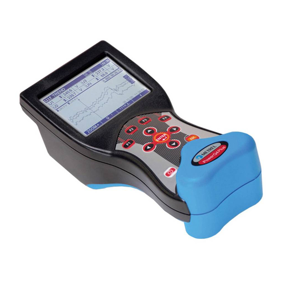
MI 2792 PowerQ4 Plus Introduction 1 Introduction PowerQ4 Plus is handheld multifunction instrument for power quality analysis and energy efficiency measurements. Figure 1.1: Instrument PowerQ4 Plus 1.1 Main Features 4 voltage channels with wide measurement range: 0 ÷ 1000 Vrms, CAT III / 1000 ... -
Page 7: Safety Considerations
MI 2792 PowerQ4 Plus Introduction Digital thermometer for temperature measurement. Powerful troubleshooting tools: transient, inrush/fast, and waveform recorder. Voltage events and user defined alarms capture. 15 hour of autonomous (battery) supply. PowerView v2.0 is a companion PC Software which provides easiest way to download, view and analyze measured data or print. -
Page 8: Applicable Standards
MI 2792 PowerQ4 Plus Introduction allowed temperature for metal part of handle. In such environment it is advisable not to touch the battery cover during or immediately after the charging. Maximum voltage between any phase and neutral input is 1000 V . - Page 9 MI 2792 PowerQ4 Plus Introduction Displacement factor including Cos / DPF (phase p displacement factor). See 5.1.5 and 5.1.6 for definition. , eP Active energy including eP (phase p energy) and eP (total energy). Minus sign indicates generated energy and plus sign, indicate consumed energy.
- Page 10 MI 2792 PowerQ4 Plus Introduction p, pg Indices. Annotation for parameter on phase p: [1, 2, 3] or phase-to-phase pg: [12, 23, 31] Power factor including PF (phase p power factor vector) and PF (total power factor vector). Minus sign indicates generated power and plus sign, , PF indicate consumed power.
- Page 11 MI 2792 PowerQ4 Plus Introduction Fundamental RMS voltage (Uh on 1 harmonics), including U (phase pgFnd p to phase g fundamental RMS voltage) and U (phase p to neutral pFnd fundamental RMS voltage). See 5.1.8 for definition voltage RMS harmonic component including U...
-
Page 12: Description
MI 2792 PowerQ4 Plus Description 2 Description 2.1 Front panel Figure 2.1: Front panel Front panel layout: Graphic display with LED backlight, 320 x 200 pixels. 1. LCD Function keys. 2. F1 – F4 Move cursor and select parameters. 3. ARROW keys Confirms new settings, step into submenu. -
Page 13: Connector Panel
MI 2792 PowerQ4 Plus Description 2.2 Connector panel Warning! I3 C Use safety test leads only! Max. permissible voltage between voltage input terminals and ground is 1000 V Figure 2.2: Top connector panel Top connector panel layout: 1 Clamp-on current transformers (I ) input terminals. -
Page 14: Bottom View
MI 2792 PowerQ4 Plus Description 2.3 Bottom view Figure 2.4: Bottom view Bottom view layout: 1. Battery compartment. 2. Battery compartment screw (unscrew to replace the batteries). 3. Serial number label. 2.4 Accessories 2.4.1 Standard accessories Table 2.1: PowerQ4 Plus standard accessories... -
Page 15: Optional Accessories
MI 2792 PowerQ4 Plus Description Voltage measurement cable, black Voltage measurement cable, green USB cable RS232 cable 12 V / 1.2 A Power supply adapter NiMH rechargeable battery, type HR 6 (AA) Soft carrying bag Instruction manual for PowerQ4 Plus Compact disk contest –... -
Page 16: Operating The Instrument
MI 2792 PowerQ4 Plus Operating the instrument 3 Operating the instrument This section describes how to operate the instrument. The instrument front panel consists of a graphic LCD display and keypad. Measured data and instrument status are shown on the display. Basic display symbols and keys description is shown on figure bellow. -
Page 17: Instrument Main Menu
MI 2792 PowerQ4 Plus Operating the instrument Current time Screen Name Recorder status: Recording Displayed Not recording range Busy First sample Hold time-stamp Last sample Options time-stamp function keys (F1 – F4) Figure 3.2: Common display symbols and labels during measurement campaign 3.1 Instrument Main Menu... -
Page 18: Instrument Main Functions
MI 2792 PowerQ4 Plus Operating the instrument GPRS modem is ready to receive user call (see section 4.2.6 for details) GPRS communication is in progress (see section 4.2.6 for details) Current time and date Table 3.2: Keys functions Select function from the “MAIN MENU”. -
Page 19: U, I, F Menu
MI 2792 PowerQ4 Plus Operating the instrument 3.2 U, I, f menu All important voltage, current and frequency parameters can be observed in the “U, I, f” menu. Measurements results can be viewed in a tabular (METER) or a graphical form (SCOPE, TREND). -
Page 20: Scope
MI 2792 PowerQ4 Plus Operating the instrument Note: In case of AD converter overloading current and voltage value will be displayed with inverted color 250.4 Note: If phase current and voltage value are not within 10% ÷ 150% of the range, their values will be displayed with inverted color 250.4... - Page 21 MI 2792 PowerQ4 Plus Operating the instrument Figure 3.11: Voltage and Figure 3.12: Voltage and current current waveform (single mode) waveform (dual mode) Table 3.5: Instrument screen symbols and abbreviations Current recorder status RECORDER is active RECORDER is busy (retrieving data from memory)
-
Page 22: Trend
MI 2792 PowerQ4 Plus Operating the instrument Show waveforms for phase L2 Show waveforms for phase L3 Show waveforms for neutral channel Summary of all phases waveforms Switch to METER view Switch to SCOPE view Switch to TREND view (available only during recording) - Page 23 MI 2792 PowerQ4 Plus Operating the instrument Figure 3.15: Voltage and Figure 3.16: Trends of all current trend (dual mode) currents Table 3.7: Instrument screen symbols and abbreviations Current recorder status: RECORDER is active RECORDER is busy (retrieving data from memory).
- Page 24 MI 2792 PowerQ4 Plus Operating the instrument Summary of all phases trends Switch to METER view. Switch to SCOPE view Switch to TREND view Return to the “MEASUREMENTS” menu screen. Frequency trend Frequency trend can be seen from METER screen by pressing function key F2.
-
Page 25: Power Menu
MI 2792 PowerQ4 Plus Operating the instrument 3.3 Power menu In POWER menu instrument show measured power parameters. Results can be seen in a tabular (METER) or a graphical form (TREND). TREND view is active only while RECORDER is active. See section 3.9 for instructions how to start recorder. In order to fully understand meanings of particular power parameter see sections 5.1.5 and 5.1.6. -
Page 26: Trend
MI 2792 PowerQ4 Plus Operating the instrument Table 3.12: Keys functions Waveform snapshoot: Hold measurement on display Save held measurement into memory Select between phase, neutral, all-phases and line view: Show measurements for phase L1 Show measurements for phase L2... - Page 27 MI 2792 PowerQ4 Plus Operating the instrument Maximal ( ), average ( ) and minimal ( ) value of consumed (Q Qip±, Qit± ) or generated (Q ) reactive inductive itot itot ± ± ± ± power (Q ) for last recorded time interval (IP) itot p: [1..3]...
-
Page 28: Energy Menu
MI 2792 PowerQ4 Plus Operating the instrument Power parameters for phase L2 Power parameters for phase L3 Power parameters L1, L2 and L3 on the same graph Total power parameters Switch to METER view (available only during recording) Switch to TREND view (available only during recording) Return to the “MEASUREMENTS”... -
Page 29: Harmonics Menu
MI 2792 PowerQ4 Plus Operating the instrument , eQ ) download data to PC and use software PowerView v2.0 in order to observe results. Pp, Pt Instantaneous phase active power (P ) or total P active power p: [1..3] Qp, Qt... - Page 30 MI 2792 PowerQ4 Plus Operating the instrument Figure 3.22: Harmonics and interharmonics meter table Description of symbols and abbreviations used in METER screens are shown in table bellow. Table 3.17: Instrument screen symbols and abbreviations Show currently displayed channel. Current recorder status:...
-
Page 31: Histogram (Bar)
MI 2792 PowerQ4 Plus Operating the instrument Harmonics / interharmonics components for phase L1 Harmonics / interharmonics components for phase L2 Harmonics / interharmonics components for phase L3 Harmonics / interharmonics components for neutral channel Summary of components on all phases... -
Page 32: Trend
MI 2792 PowerQ4 Plus Operating the instrument Ip, In True effective phase current I p:1..3 ThdU Total voltage harmonic distortion THD ThdI Total current harmonic distortion THD hn/ihn n-th voltage or current harmonic / interharmonic component Uh /iUh / iIh n: 0..50... - Page 33 MI 2792 PowerQ4 Plus Operating the instrument Figure 3.24: Harmonics and interharmonics trends screens Table 3.21: Instrument screen symbols and abbreviations Current recorder status: RECORDER is active RECORDER is busy (retrieving data from memory) Current instrument time ThdU Maximal ( ) and average ( ) value of total voltage harmonic distortion...
- Page 34 MI 2792 PowerQ4 Plus Operating the instrument Select between trending various parameters. By default these are: Total harmonic distortion for selected phase (THDU harmonics / interharmonics for selected phase (U harmonics / interharmonics for selected phase (U harmonics / interharmonics for selected phase (U...
-
Page 35: Flickermeter
MI 2792 PowerQ4 Plus Operating the instrument 3.6 Flickermeter Flickermeter measures the human perception of the effect of amplitude modulation on the mains voltage powering a light bulb. In Flickermeter menu instrument shows measured flicker parameters. Results can be seen in a tabular (METER) or a graphical form (TREND) - which is active only while RECORDER is active. -
Page 36: Trend
MI 2792 PowerQ4 Plus Operating the instrument Switch to METER view (available only during recording) Switch to TREND view (available only during recording) Exit from “HOLD” screen without saving. Return to the “MEASUREMENTS” menu screen. 3.6.2 Trend During active recording TREND view is available (see section 3.9 for instructions how to start recording). -
Page 37: Phase Diagram
MI 2792 PowerQ4 Plus Operating the instrument Show long term flicker P Show 1 min short term flicker P st1min Select between trending various parameters: Show selected flicker trends for phase 1 Show selected flicker trends for phase 2 Show selected flicker trends for phase 3... -
Page 38: Symmetry Diagram
MI 2792 PowerQ4 Plus Operating the instrument Current instrument time U1, U2, U3 Fundamental voltages U 1Fnd 2Fnd 3Fnd I1, I2, I3 Fundamental currents I 1Fnd 2Fnd 3Fnd Displacement factor (cos φ) for particular phase: , DPF Indicate current and voltage scaling. -
Page 39: Symmetry Trend
MI 2792 PowerQ4 Plus Operating the instrument Table 3.30: Instrument screen symbols and abbreviations Current recorder status: RECORDER is active RECORDER is busy (retrieving data from memory) RECORDER is not active Current instrument time Zero sequence voltage component U Zero sequence current component I... - Page 40 MI 2792 PowerQ4 Plus Operating the instrument Figure 3.29: Symmetry trend screen Table 3.32: Instrument screen symbols and abbreviations Current recorder status: RECORDER is active RECORDER is busy (retrieving data from memory) Current instrument time Usym- Maximal ( ), average ( ) and minimal ( ) value of negative sequence...
-
Page 41: Temperature
MI 2792 PowerQ4 Plus Operating the instrument 3.8 Temperature PowerQ4 Plus instrument is capable of measuring and recording temperature. Temperature is expressed in both units, Celsius and Fahrenheit degrees. See following sections for instructions how to start recording. In order to learn how to set up neutral clamp input with the temperature sensor, see section 4.2.4. -
Page 42: General Recorder
MI 2792 PowerQ4 Plus Operating the instrument Figure 3.31: Temperature trend screen Table 3.36: Instrument screen symbols and abbreviations Current recorder status Instrument is recording Instrument is busy (saving data to memory) Current instrument time Maximal ( ), average ( ) and minimal ( ) temperature value for last... - Page 43 MI 2792 PowerQ4 Plus Operating the instrument Figure 3.32: Basic recorder setup screen In following table description of recorder settings is given: Table 3.38: Recorder settings description Select type of recording. Following options are available and can be set by using configuration menu: ...
- Page 44 MI 2792 PowerQ4 Plus Operating the instrument Harmonics – select which voltage and current harmonics you want to include in the record. User can choose: o First and last voltage and current harmonic to record; o Select even, odd or all harmonics components for recording.
-
Page 45: Waveform Recorder
MI 2792 PowerQ4 Plus Operating the instrument Table 3.39: Keys functions Start the recorder Stop the recorder Open configuration sub menu. Possible options are: “EN50160” – predefined configuration for EN 50160 survey. Configuration 1 - user defined configuration. - Page 46 MI 2792 PowerQ4 Plus Operating the instrument Figure 3.33: Waveform recorder setup screen. Table 3.40: Instrument screen symbols and abbreviations Select logging signals: Signals Trigger source set up: Manual - triggered by a F1 - TRIG key; Events – triggered by voltage event;...
-
Page 47: Capturing Waveform
MI 2792 PowerQ4 Plus Operating the instrument If “Trigger source” is selected, change Trigger source. If SIGNALS dialog box is open, scroll through all channels. If “Store buffer” is selected, change Store buffer size. If “Pre – trigger length” is selected, change pre – trigger buffer size. -
Page 48: Captured Waveform
MI 2792 PowerQ4 Plus Operating the instrument Show voltage and current waveform (single mode); Show voltage and current waveform (dual mode). Select between phase, neutral, all-phases and line view: Show waveforms for phase L1; Show waveforms for phase L2;... - Page 49 MI 2792 PowerQ4 Plus Operating the instrument Total harmonic distortion THD and THD Crest factor Cf and Cf PEAK Peak value U and I Maximal U voltage U and maximal I current, Rms(1/2) Rms(1/2)Max ½Rms MAX 1/2 measured from last RESET (key: F2).
- Page 50 MI 2792 PowerQ4 Plus Operating the instrument Voltage/current scale and the top/bottom of the scope screen Cursor position time. Table 3.47: Keys functions - SCOPE Zoom in. Zoom out. Select between the following signals: Show voltage waveform; Show current waveform;...
-
Page 51: Inrush / Fast Recorder
MI 2792 PowerQ4 Plus Operating the instrument Table 3.48: Instrument screen symbols and abbreviations - TREND Current recorder status; Instrument is recording; Instrument is busy (retrieving data from memory); Instrument is not in recording mode. Current instrument time. -
Page 52: Setup
MI 2792 PowerQ4 Plus Operating the instrument This function is based on a principle of logging data exceeding the set (trigger) level with positive, negative or both slopes on a current or voltage input. When trigger occurs, data capturing begins. Instrument record until Duration time has ben reach. -
Page 53: Capturing Inrush
MI 2792 PowerQ4 Plus Operating the instrument Table 3.51: Keys functions Start the inrush logger. Toggle between voltage and current trigger signal selection (Only in “Trigger” dialog window). Note: If user forces inrush logging to stop no data is recorded. -
Page 54: Captured Inrush
MI 2792 PowerQ4 Plus Operating the instrument Current instrument time. U1..UN True effective voltage value U Rms(10). True effective current value U I1..IN Rms(10). Total harmonic distortion THD or THD Frequency on reference channel. Settled trigger value. Trig Represent current (voltage) value at the top of the graph (horizontal line between graph and table values). - Page 55 MI 2792 PowerQ4 Plus Operating the instrument Figure 3.40: Captured inrush Table 3.54: Instrument screen symbols and abbreviations Instrument loading data from memory. Show record number in MEMORY LIST. Current instrument time. Indicate position of the cursor at the graph.
-
Page 56: Transients Recorder
MI 2792 PowerQ4 Plus Operating the instrument Scroll the cursor along logged data. Return to the “INRUSH LOGGER” setup screen. 3.12 Transients recorder Transient is a term for short, highly damped momentary voltage or current disturbance. A transient recording is recording with the 25 kHz sampling rate. The principle of measurement is similar to waveform recording, but with a 10 times higher sampling rate (1024 samples per period). -
Page 57: Capturing Transients
MI 2792 PowerQ4 Plus Operating the instrument Table 3.57: Keys functions Start transient recorder. Stop transient recorder. Note: If user forces transients recorder to stop no data is recorded. Data recording occurs only when trigger is activated. Manually generate trigger condition (Active only if Manual trigger selected and recording in progress). -
Page 58: Captured Transients
MI 2792 PowerQ4 Plus Operating the instrument Table 3.59: Keys function Manually generate trigger condition (Active only if Manual trigger selected and recording is in progress). Select which waveforms to show: Show voltage waveform; Show current waveform; Show voltage and current waveform (single mode);... - Page 59 MI 2792 PowerQ4 Plus Operating the instrument Table 3.60: Instrument screen symbols and abbreviations Current instrument time. Show record number in MEMORY LIST. U1, U2, U3, UN, U12, True effective value of voltage – U Rms(10). U23, U31 I1, I2, I3, IN True effective value of current –...
- Page 60 MI 2792 PowerQ4 Plus Operating the instrument Figure 3.44: Captured transients RMS trend screen Table 3.62: Instrument screen symbols and abbreviations Current instrument time. Show record number in MEMORY LIST. U1, U2, U3, UN, U12, True effective value of voltage – U Rms(10).
-
Page 61: Events Table
MI 2792 PowerQ4 Plus Operating the instrument Set vertical zoom (Only if cursor assigned to transients scope). Move cursor position. Return to the “TRANSIENTS SETUP” screen. 3.13 Events table In this table captured voltage dips, swells and interrupts are shown. Note that events appear in the table after finishing, when voltage return to the normal value. - Page 62 MI 2792 PowerQ4 Plus Operating the instrument Table 3.64: Instrument screen symbols and abbreviations Current recorder status: RECORDER is active RECORDER is busy (retrieving data from memory) RECORDER is not active Date Date when selected event has occurred Unified event number (ID) Indicate phase or phase-to-phase voltage where event has occurred: 1 –...
- Page 63 MI 2792 PowerQ4 Plus Operating the instrument Select event. Exit from detailed view of an event. Back to the “RECORDERS” menu screen. Phase view In this view voltage events are separated by phases. This is convenient view for troubleshooting. Additionally user can use filters in order to observe only particular type of event on a specific phase.
- Page 64 MI 2792 PowerQ4 Plus Operating the instrument 3 – event on phase U 12 – event on voltage U 23 – event on voltage U 31 – event on voltage U Start Event start time (when first U ) value cross threshold.
-
Page 65: Alarms Table
MI 2792 PowerQ4 Plus Operating the instrument Select event. Exit from detailed view of an event. Back to the “RECORDER” menu screen. 3.14 Alarms table This menu shows list of alarms which went off. Alarms are displayed in a table, where each row represents an alarm. -
Page 66: Memory List
MI 2792 PowerQ4 Plus Operating the instrument Slope Indicates alarms transition: Rise – parameter has over-crossed threshold Fall – parameter has under-crossed threshold Level Minimal or maximal parameter value during alarm occurrence Duration Alarm duration. Table 3.69: Keys function... - Page 67 MI 2792 PowerQ4 Plus Operating the instrument Figure 3.49: Memory list screen Table 3.70: Instrument screen symbols and abbreviations Current recorder status RECORDER is active RECORDER is busy (retrieving data from memory) RECORDER is not active Current instrument time Record No Selected record number, for which details are shown.
-
Page 68: Record
MI 2792 PowerQ4 Plus Operating the instrument 3.15.1 Record This type of record is made by RECORDER. Record front page is similar to the RECORDER menu, as shown on figure bellow. Figure 3.50: Front page of Record in MEMORY LIST menu Table 3.72: Recorder settings description... - Page 69 MI 2792 PowerQ4 Plus Operating the instrument Select parameter (only in CHANNELS SETUP menu). Back to the previous menu. By pressing in CHANNELS SETUP menu TREND screen will appear. TREND type depends on the position of a cursor. Typical screen is shown on figure bellow.
-
Page 70: Waveform Snapshoot
MI 2792 PowerQ4 Plus Operating the instrument Table 3.75: Keys functions Zoom in. Zoom out. Select between the following options: Show voltage trend; Show current trend; Show voltage and current trend in single graph; Show voltage and current trend in two separate graphs. -
Page 71: Waveform Record
MI 2792 PowerQ4 Plus Operating the instrument 3.15.3 Waveform record This type of record is made by Waveform recorder. For details regarding manipulation and data observing see section Captured waveform3.10.3 3.15.4 Inrush/Fast logger This type of record is made by Inrush logger. For details regarding manipulation and data observing see section 3.11.3. -
Page 72: Connection Setup
MI 2792 PowerQ4 Plus Operating the instrument 3.16.1 Connection setup Figure 3.54: “CONNECTION SETUP” screen Table 3.78: Description of Connection setup Nominal voltage range. Select voltage range according to the nominal network voltage. 1W and 4W 50 ÷ 110V (L-N) 86÷190 V (L-L) - Page 73 MI 2792 PowerQ4 Plus Operating the instrument Connection Method of connecting the instrument to multi phase systems (see 4.2.1 for details). 1W: 1-phase 2-wire system; 3W: 3-phase 3-wire system; 4W: 3-phase 4-wire system. Synchronization channel. This channel is used for instrument synchronization to the network frequency.
-
Page 74: Event Setup
MI 2792 PowerQ4 Plus Operating the instrument 3.16.2 Event setup In this menu you can setup voltage events and their parameters. See 5.1.12 for further details regarding measurement methods. Captured events can be observed through EVENTS TABLE menu. See 3.13 for details. - Page 75 MI 2792 PowerQ4 Plus Operating the instrument Figure 3.56: Alarms setup screen. Table 3.82: Description of Alarms setup column Select alarm from measurement group then measurement itself. (f, P+ on figure above) column Select phases for alarms capturing (Tot on figure above) ...
-
Page 76: Signalling Setup
MI 2792 PowerQ4 Plus Operating the instrument Enter or exit a sub menu to set an alarm. Cursor keys. Select parameter. Cursor keys. Select parameter or change value. Confirm setting of an alarm Back to the “MEASUREMENT SETUP” menu screen. -
Page 77: Communication
MI 2792 PowerQ4 Plus Operating the instrument Figure 3.58: GENERAL SETUP menu Table 3.85: Description of General setup options Communication Setup communication baud rate and source. Time & Date Set time and date. Language Select language. Clear Memory Clear instrument memories. - Page 78 MI 2792 PowerQ4 Plus Operating the instrument Table 3.87: Description of Communication setup options Source: Select RS-232 or USB communication port. Baud rate: Select port speed. Show status of GPRS communication. GPRS is enabled only GPRS*: after INIT sequence was successfully applied.
-
Page 79: Time & Date
MI 2792 PowerQ4 Plus Operating the instrument 3.17.2 Time & Date Time and date can be set in this menu. Figure 3.60: Set time & date screen Table 3.89: Keys functions Select between the following parameters: hour, minute, second, day, month or year. -
Page 80: Clear Memory
MI 2792 PowerQ4 Plus Operating the instrument Table 3.90: Keys functions Select language. Confirm the selected language. Back to the “GENERAL SETUP” menu screen. 3.17.4 Clear Memory Use this menu in order to clear different instrument memory. User can select one of following items to clear: Figure 3.62: Clear menu screen... -
Page 81: Instrument Info
MI 2792 PowerQ4 Plus Operating the instrument 3.17.5 Instrument info Basic information concerning the instrument can be viewed in this menu: company, user data, serial number, firmware version and hardware version. Figure 3.63: Instrument info screen Table 3.93: Keys functions Back to the “GENERAL SETUP”... - Page 82 MI 2792 PowerQ4 Plus Operating the instrument Table 3.94: Keys function Select digit Change value of the selected digit Set / Confirm lock code. Back to the “GENERAL SETUP” menu screen. Following table shows how locking impacts instrument functionality. Table 3.95: Locked instrument functionality...
-
Page 83: Recording Practice And Instrument Connection
MI 2792 PowerQ4 Plus Recording Practice and Instrument Connection 4 Recording Practice and Instrument Connection In following section recommended measurement and recording practice is described. 4.1 Measurement campaign Power quality measurements are specific type of measurements, which can last many days, and mostly they are performed only once. - Page 84 MI 2792 PowerQ4 Plus Recording Practice and Instrument Connection Start Prepare instrument for new measurement, before going to measuring site. Check: · Is it time and date correct? Step 1: · Are batteries in good condition? · Is it Memory List empty? If it is not, ·...
- Page 85 MI 2792 PowerQ4 Plus Recording Practice and Instrument Connection Step 1: Instrument setup On site measurements can be very stressful, and therefore it is good practice to prepare measurement equipment in an office. Preparation of PowerQ4 Plus include following steps: ...
- Page 86 MI 2792 PowerQ4 Plus Recording Practice and Instrument Connection Step 2.4: Event setup (optional) Use this step only if voltage events are object of concern. Select nominal voltage and threshold values for: dip, swell and interrupts (see sections 3.16.2 and 3.13 for details).
-
Page 87: Connection Setup
MI 2792 PowerQ4 Plus Recording Practice and Instrument Connection Include events and alarms capture if necessary After setting recorder, recording can be started. (see section 3.9 for recorder details). Note: Recording usually last few days. Assure that instrument during recording session is not reachable to the unauthorized persons. - Page 88 MI 2792 PowerQ4 Plus Recording Practice and Instrument Connection 3-phase 4-wire system In order to select this connection scheme, choose following connection on the instrument: Figure 4.3: Choosing 3-phase 4-wire system on instrument Instrument should be connected to the network according to figure bellow: LN L3 C Figure 4.4: 3-phase 4-wire system...
- Page 89 MI 2792 PowerQ4 Plus Recording Practice and Instrument Connection Figure 4.5: Choosing 3-phase 3-wire system on instrument Instrument should be connected to the network according to figure bellow. LN L3 C Figure 4.6: 3-phase 3-wire system 1-phase 3-wire system In order to select this connection scheme, choose following connection on the instrument: Figure 4.7: Choosing 1-phase 3-wire system on instrument...
-
Page 90: Connection To The Mv Or Hv Power System
MI 2792 PowerQ4 Plus Recording Practice and Instrument Connection Instrument should be connected to the network according to figure bellow. LN L3 C Figure 4.8: 1-phase 3-wire system Note: In case of events capturing, it is recommended to connect unused voltage inputs to N voltage input. -
Page 91: Current Clamp Selection And Transformation Ratio Setting
Direct current measurement can be performed by any clamp-on current transformer. We particularly recommend Smart clamps: flex clamps A 1227 and iron clamps A 1281. Also older Metrel clamp models A 1033 (1000A), A1069 (100A), A1120 (3000A), A1099 (3000A), etc. can be used. - Page 92 MI 2792 PowerQ4 Plus Recording Practice and Instrument Connection Figure 4.11: Parallel feeding of large load Example: 2700 A current load is feed by 3 equal parallel cables. In order to measure current we can embrace only one cable with clamps, and select: Measuring on wires: 3 in clamp menu.
- Page 93 MI 2792 PowerQ4 Plus Recording Practice and Instrument Connection 100A load feeding 100 A Load Current Transformer: Current clamps: 600A : 5A A1122 (5A/1V) Measuring Setup: I Range: 100% Measuring setup: Current transformer: Prim: 600 Sec: 5 PowerQ4 display: Irms = 100 A Figure 4.12: Current clamps selection for indirect current measurement...
- Page 94 Recording Practice and Instrument Connection Automatic current clamps recognition Metrel developed Smart current clamps product family in order to simplify current clamps selection and settings. Smart clamps are multi-range switch-less current clamps automatically recognized by instrument. In order to activate smart clamp recognition, the following procedure should be followed for the first time: 1.
-
Page 95: Temperature Probe Connection
MI 2792 PowerQ4 Plus Recording Practice and Instrument Connection Table 4.1: Clamp status screen symbols and abbreviations Show clamps, which were connected during clamp setup in Measurement setupConnection SetupPh./N. Curr. clamps X: clamps on present current channel are missing Setup ... -
Page 96: Gps Time Synchronization Device Connection
MI 2792 PowerQ4 Plus Recording Practice and Instrument Connection Figure 4.17: Detected temperature probe pop up window 4.2.5 GPS time synchronization device connection PowerQ4 Plus has the ability to synchronize its system time clock with Coordinated Universal Time (UTC time) provided by externally connected GPS module (optional accessory - A 1355). -
Page 97: Gprs Modem Connection
MI 2792 PowerQ4 Plus Recording Practice and Instrument Connection When the time zone is set, PowerQ4 Plus will synchronize its system time clock and internal RTC clock with the received UTC time. GPS module also provides the instrument with extremely accurate synchronization pulses every second (PPS – Pulse Per Second) for synchronization purposes in case of lost satellite reception. -
Page 98: Number Of Measured Parameters And Connection Type Relationship
MI 2792 PowerQ4 Plus Recording Practice and Instrument Connection Figure 4.20: GPRS test screen For detailed information please check user manual of A 1356 GPRS Modem. 4.3 Number of measured parameters and connection type relationship Parameters which PowerQ4 Plus displays and measures, mainly depends on network type, defined in CONNECTION SETUP menu, Connection type. - Page 99 MI 2792 PowerQ4 Plus Recording Practice and Instrument Connection 1÷50 1÷50 1÷50 1÷50 1÷50 1÷50 1÷50 1÷50 1÷50 1÷50 1÷50 1÷50 1÷50 1÷50 1÷50 1÷50 1÷50 1÷50 1÷50 1÷50 1-50 1÷50 1÷50 1÷50 1÷50 1÷50 1÷50 1÷50 1÷50 1÷50 1-50 1÷50...
- Page 100 MI 2792 PowerQ4 Plus Recording Practice and Instrument Connection Table 4.6: Quantities recorder by instrument 1-phase Value Voltage 1Rms NRms 12Rms 23Rms 31Rms 1Rms 2Rms 3Rms NRms 12Rms 23Rms 31Rms Current 1rms Nrms 1rms 2rms 3rms 1rms 2rms 3rms Nrms...
-
Page 101: Theory And Internal Operation
MI 2792 PowerQ4 Plus Theory and internal operation 5 Theory and internal operation This section contains basic theory of measuring functions and technical information of the internal operation of the PowerQ4 Plus instrument, including descriptions of measuring methods and logging principles. -
Page 102: Current Measurement (Magnitude Of Supply Current)
MI 2792 PowerQ4 Plus Theory and internal operation 1024 Line voltage: [V], pg: 12,23,31 1024 Phase voltage crest factor: , p: 1,2,3,N Line voltage crest factor: pgPk , pg: 12, 23, 31 The instrument has internally 3 voltage measurement ranges. Middle voltage (MV) and high voltage (HV) systems can be measured on lowest voltage range with assistance of voltage transformers. -
Page 103: Phase Power Measurements
MI 2792 PowerQ4 Plus Theory and internal operation For RECORDING with aggregation time Interval: <10 sec and on-line measurements, frequency reading is obtained from 10 cycles, in order to decrease instrument response time. The frequency is ratio of 10 cycles, divided by the duration of the integer cycles. -
Page 104: Energy
MI 2792 PowerQ4 Plus Theory and internal operation PFtot Total power factor (vector): (16) Figure 5.2: Vector representation of total power calculus 5.1.7 Energy Standard compliance: IEC 61557-12 (Annex A) Energy counters are linked to RECORDER functionality. Energy counters measure energy only when RECORDER is active. -
Page 105: Harmonics And Interharmonics
MI 2792 PowerQ4 Plus Theory and internal operation 2. Last integration period LST.IP counter measures energy during recording over last interval. It is calculated at end of each interval. 3. Current integration period CUR.IP counter measures energy during recording over current time interval. -
Page 106: Signallling
MI 2792 PowerQ4 Plus Theory and internal operation Phase voltage and current harmonics are calculated as RMS value of harmonic subgroup (sg): square root of the sum of the squares of the RMS value of a harmonic and the two spectral components immediately adjacent to it. -
Page 107: Flicker
MI 2792 PowerQ4 Plus Theory and internal operation Signalling voltage is calculated on a FFT spectrum of a 10-cycle interval. Value of mains signalling voltage is measured as: RMS value of a single frequency bin if signalling frequency is equal to spectral bin frequency, or ... -
Page 108: Voltage And Current Unbalance
MI 2792 PowerQ4 Plus Theory and internal operation Figure 5.7: Curve of equal severity (Pst=1) for rectangular voltage changes on LV power supply systems – is a short flicker estimation based on 1-minute interval. It is calculated as stp1min running average and is used to get quick preview of 10 minutes. -
Page 109: Voltage Events
MI 2792 PowerQ4 Plus Theory and internal operation where For unbalance calculus, instrument use the fundamental component of the voltage input signals (U ), measured over a 10-cycle time interval. The negative sequence ratio u , expressed as a percentage, is evaluated by: ... - Page 110 MI 2792 PowerQ4 Plus Theory and internal operation with the time of the end of the U that ended the event, as defined by the Rms(1/2) threshold. The duration of a voltage dip is the time difference between the start time and the end time of the voltage dip.
-
Page 111: Alarms
MI 2792 PowerQ4 Plus Theory and internal operation U – maximum swell magnitude voltage is the largest U value measured Swell Rms(1/2) on any channel during the swell. The start time of a swell is time stamped with the time of the start of the U... -
Page 112: Data Aggregation In General Recording
MI 2792 PowerQ4 Plus Theory and internal operation Each alarm has attributes described in table bellow. Alarm occurs when 10-cycle measured value on phases defined as Phase, cross Threshold value according to defined Trigger slope, minimally for Minimal duration value. - Page 113 MI 2792 PowerQ4 Plus Theory and internal operation Figure 5.9: Synchronization and aggregation of 10 cycle intervals For each aggregation interval instrument computes average value for measured quantity. Depending from the quantity, this can be RMS (root means square) or arithmetical average.
- Page 114 MI 2792 PowerQ4 Plus Theory and internal operation Arithmetic Arithmetic Arithmetic DPF (cos φ) Arithmetic Symmetry 1÷50 Harmonics 1÷50 1÷50 Interharmonics 1÷50 Signalling Parameter which will be recorded during recording session depends on Connection and Synchronization channel, as shown in Table 4.6. For each parameter: ...
- Page 115 MI 2792 PowerQ4 Plus Theory and internal operation Active attribute for particular quantity is set if: Phase/line RMS value is greater than lower limit of a measuring range (details in technical specification): voltage and current effective value, harmonics and THD, voltage flicker.
-
Page 116: Waveform Snapshoot
MI 2792 PowerQ4 Plus Theory and internal operation = na = Pf = na = na = na = na = Pf = na ePpos = 0 GENERATOR MODE MOTOR MODE ePpos = P ePneg = P ePneg = 0... -
Page 117: Transient Recorder
MI 2792 PowerQ4 Plus Theory and internal operation Voltage events and alarms - start waveform recorder when either voltage event or alarm occur User can perform single or continuous waveform recordings. In continuous waveform recording, PowerQ4 Plus will automatically initialize next waveform recording upon completion of the previous one. - Page 118 MI 2792 PowerQ4 Plus Theory and internal operation Measured signal Inrush, fluctuation or other event Inrush logger ½Rms U or I Trigger Level Slope: Figure 5.12: Inrush (waveform and RMS) Storage buffer is divided into pre-buffer (measured values before trigger point) and post- buffer (measured values after trigger point).
-
Page 119: En 50160 Standard Overview
MI 2792 PowerQ4 Plus Theory and internal operation User can choose to perform single or continuous inrush loggings. If continuous inrush logging is performed, PowerQ4 Plus will automatically initialize next inrush logging upon completion of the previous one. Two initial consecutive inrush loggings can be performed without “dead time”... -
Page 120: Supply Voltage Variations
MI 2792 PowerQ4 Plus Theory and internal operation 5.2.2 Supply voltage variations Under normal operating conditions, during each period of one week 95 % of the 10 min mean U values of the supply voltage shall be within the range of U ±... -
Page 121: Interharmonic Voltage
MI 2792 PowerQ4 Plus Theory and internal operation 1,5 % 1,5 % 1,5 % 5.2.8 Interharmonic voltage The level of interharmonics is increasing due to the development of frequency converters and similar control equipment. Levels are under consideration, pending more experience. - Page 122 MI 2792 PowerQ4 Plus Theory and internal operation Figure 5.15: Predefined EN50160 recorder configuration After recording is finished, EN 50160 survey is performed on PowerView v2.0 software. See PowerView v2.0 manual or details. Note: In EN 50160 recording only average values are stored.
-
Page 123: Technical Specifications
MI 2792 PowerQ4 Plus Technical specifications 6 Technical specifications 6.1 General specifications Working temperature range: -10 C ÷ +50 C Storage temperature range: -20 C ÷ +70 C 95 % RH (0 C ÷ 40 C), non-condensing Max. -
Page 124: Phase Voltages
MI 2792 PowerQ4 Plus Technical specifications NOTE: Instrument has 3 voltage ranges. Range has to be chosen according to the network nominal voltage, according to the table bellow. Nominal phase voltage: U Recommended Voltage range 50 V ÷ 110 V Voltage Range 1: 50 V ÷... -
Page 125: Line Voltages
MI 2792 PowerQ4 Plus Technical specifications 6.2.3 Line voltages , pg: [12, 23, 31], AC+DC pgRms Measuring range Resolution Accuracy Crest factor Range 1: 20.0 V ÷ 260.0 V ± 0.25 % · 100 mV min 1.5 Range 2: 47.0 V ÷... -
Page 126: Frequency
MI 2792 PowerQ4 Plus Technical specifications 1.00 ÷ 10.00 0.01 ± 5 % · Cf Current accuracy with clamps Measurement accessory Measuring range Overall current accuracy ±1.4 % I 1000 A A ÷ 1200 100 A ±0.4 % I 10 A ÷... -
Page 127: Power Factor (Pf)
MI 2792 PowerQ4 Plus Technical specifications ±0.5 % S Excluding clamps 0.000 k ÷ 999.9 M With A 1227 ±1.8 % S 0.000 k ÷ 999.9k Flex clamps 4 digits With A 1281 ±0.8 % S 0.000 k ÷ 999.9k... -
Page 128: Voltage Harmonics And Thd
MI 2792 PowerQ4 Plus Technical specifications With A 1033 ±1.6 % eS 000,000,000.001 ÷ 999,999,999.999 1000 A *Accuracy values are valid if cos φ 0.80, I 10 % I and U 80 % U ... -
Page 129: Signalling
MI 2792 PowerQ4 Plus Technical specifications 6.2.15 Signalling Measuring range Resolution Accuracy ± 0.15 % U 1 % U < U < 3 % U 10 mV ± 5 % U 3 % U < U < 20 % U... -
Page 130: Recorders
MI 2792 PowerQ4 Plus Technical specifications 6.3 Recorders 6.3.1 General recorder Sampling 5 readings per second, continuous sampling per channel. All channels are sampled simultaneously. Sampling frequency is continuously synchronized with main frequency. Recording time From 30 min with 1 second display resolution up to 99 days with 1 hour display resolution. -
Page 131: Waveform Snapshoot
MI 2792 PowerQ4 Plus Technical specifications quantities ), I 31Rms(1/2) 1½Rms 2½Rms 3½Rms N½Rms For 50 Hz mains frequency No. of signals Duration 686 s 514 s 343 s 205 s Trigger Percent of nominal voltage or current range (rise, fall or both edges) 6.3.4 Waveform snapshoot... - Page 132 MI 2792 PowerQ4 Plus Technical specifications 5 % ÷ 200% I 5 % ÷ 200% I - 1 ÷ 1 0.02 10 Hz ÷ 70 Hz I, I 5 % I ÷ 200 % 20 V ÷ 1000 V 0.4 ÷ 4 5 V ÷...
-
Page 133: Compliance To The To The Iec 61000-4-30
MI 2792 PowerQ4 Plus Technical specifications 6.4.2 Compliance to the to the IEC 61000-4-30 Measurement PowerQ4 IEC 61000-4-30 Section and Method - Uncertainty Measuring Influence Aggregation Plus Class Parameter IEC 61000-4- range Quantity range Method Parameter 30 Section 5.1 Frequency freq 5.1.1... -
Page 134: Maintenance
MI 2792 PowerQ4 Plus Maintenance 7 Maintenance 7.1 Inserting batteries into the instrument Make sure that the power supply adapter/charger and measurement leads are disconnected and the instrument is switched off. Insert batteries as shown in figure bellow (insert batteries correctly, otherwise the instrument will not operate and the batteries could be discharged or damaged). -
Page 135: Batteries
MI 2792 PowerQ4 Plus Maintenance Hazardous voltages exist inside the instrument. Disconnect all test leads and remove the power supply cable before removing battery compartment cover. Use only power supply adapter/charger delivered from manufacturer or distributor of the equipment to avoid possible fire or electric shock. -
Page 136: Power Supply Considerations
MI 2792 PowerQ4 Plus Maintenance checking them in a cell charger etc). It is very likely that only some of the batteries are deteriorated. The effects described above should not be mixed with normal battery capacity decrease over time. All charging batteries lose some of their capacity when repeatedly charged/discharged. - Page 137 MI 2792 PowerQ4 Plus Maintenance Manufacturer address: METREL d.d. Ljubljanska 77, SI-1354 Horjul, Slovenia Tel: +(386) 1 75 58 200 Fax: +(386) 1 75 49 095 Email: metrel@metrel.si http://www.metrel.si...
- Page 138 MI 2792 PowerQ4 Plus Maintenance...
Need help?
Do you have a question about the MI 2792 PowerQ4 Plus and is the answer not in the manual?
Questions and answers