Jungheinrich EJE 116 Operating Instructions Manual
Hide thumbs
Also See for EJE 116:
- Operating instructions manual (163 pages) ,
- Operating instructions manual (194 pages)
Table of Contents
Advertisement
Advertisement
Chapters
Table of Contents

Related Manuals for Jungheinrich EJE 116


Summary of Contents for Jungheinrich EJE 116
- Page 1 EJE 116/118/120 10.03 - Operating instructions 50425855 06.06...
- Page 2 Used to indicate standard equipment. Used to indicate optional equipment. Our trucks are subject to ongoing development. Jungheinrich reserves the right to alter the design, equipment and technical features of the truck. No guarantee of particular features of the truck should therefore be inferred from the present operating instructions.
-
Page 4: Table Of Contents
Table of contents Correct use and application of the truck Truck description Description of use ................B 1 Description of assemblies and functions ..........B 2 Technical data - Standard version ............B 3 Performance data for standard trucks ..........B 3 Dimensions .................. - Page 5 Safety regulations applicable to truck maintenance ......F 1 Servicing and inspection ..............F 3 Maintenance Check - list EJE 116 / 118 / 120 ........F 4 Lubrication Schedule EJE 116 / 118 / 120 ......... F 6 Fuels, coolants and lubricants ............. F 7 Instructions for the servicing operations ..........
- Page 6 Appendix JH Traction Battery Operating Instructions These operating instructions apply only to Jungheinrich battery models. If using another brand, refer to the manufacturer's operating instructions.
-
Page 8: A Correct Use And Application Of The Truck
A Correct use and application of the truck The “Guidelines for the Correct Use and Application of Industrial Trucks” (VDMA) are included in the scope of delivery for this truck. The guidelines are part of these oper- ating instructions and must always be heeded. National regulations are fully applica- ble. -
Page 10: B Truck Description
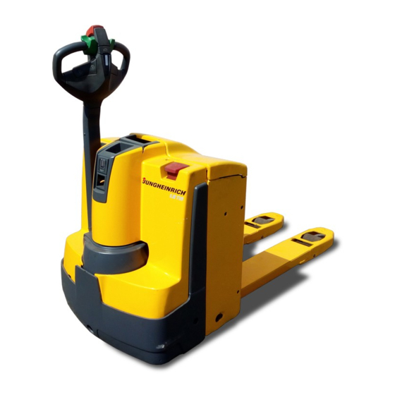
The load capacity can be found on the load capacity label Qmax. Truck type, load capacity and motor output: Type Load capacity Motor output EJE 116 1,600 kg 1.0 kW EJE 118 1,800 kg 1.0 kW... -
Page 11: Description Of Assemblies And Functions
Description of assemblies and functions Item Designation Item Designation t Discharge indicator t Load lifting device o Display instrument o Integrated charging device (CANDIS) 24V/30A (incl. safety circuit) o Keyboard t Battery hood (CANCODE) t Key switch t Controller o Key switch t Collision safety device (with an additional second stage for brake release) -
Page 12: Technical Data - Standard Version
Technical data - Standard version Description of the technical data according to VDI 2198. Technical modifications and additions reserved. Performance data for standard trucks Designation EJE 116 EJE 118 EJE 120 Load capacity 1,600 1,800 2,000 Load centre distance for standard... -
Page 14: En Standards
EN standards Continuous sound level: 70 dB(A) according to EN 12053 as stipulated in ISO 4871 The continuous sound level is a value averaged according to standard regulations, taking the sound pressure level into account when driving, lifting and idling. The sound pressure level is measured at the ear. -
Page 15: Labels And Plates
Labels and plates 2000 Item Designation Truck identification plate Load capacity Qmax Prohibition sign “Do not ride on truck” Lifting point for crane transportation Plate confirming accident prevention checks (only D) - Page 16 Truck identification plate Item Designation Item Designation Type Manufacturer logo Serial No. Min./max. battery weight in kg Rated capacity in kg Drive power in kW System voltage V Load centre distance in mm Dead weight without battery in kg Year of manufacture Manufacturer Option The load lifting device must be lifted to read the identification plate.
-
Page 18: C Transportation And Commissioning
C Transportation and commissioning Transportation by crane Only use lifting equipment with sufficient load capacity. Transportation weight = dead weight + battery weight; see truck identification plate.) Lifting points (1) are supplied on the chassis for transporting the truck using a crane. –... -
Page 19: Moving An Incapacitated Truck
Moving an incapacitated truck In order to be able to move the truck in emergency operation, the electromagnetically operated brake must be released. – Remove the front hood (2) (see Chapter F). – Remove the right-hand drive cover (3) (see Chapter F). –... -
Page 20: Emergency Operation With Service Key 741 (O)
Emergency operation with service key 741 (o) The EJE can be manually moved in case of faults in the electric system. A battery must be in the truck and connected. Set service key 741 (o) (701 is standard) to position 2 of the key switch. Key 701 for normal truck operation can be turned to key switch position 1 only. -
Page 22: D Battery - Servicing, Recharging, Replacement
D Battery - Servicing, recharging, replace- ment Safety regulations governing the handling of lead-acid batteries The truck must be parked and rendered safe before any operations on batteries are undertaken (refer to chapter E). Servicing staff: Recharging, servicing and replacing of batteries must only be per- formed by qualified personnel. -
Page 23: Battery Type
Battery type For the battery weight, refer to the battery identification plate. Depending on the use, the EJE is equipped with different types of batteries. (refer to chapter B). Batteries with non-insulated poles must be covered with an anti-slip insulating jacket. When changing / assembling the battery, make sure that it is properly fixed in the bat- tery compartment the truck. -
Page 24: Exposing The Battery
Exposing the battery – Safely park the truck (see Chapter E). – Open the battery hood (2). To do so, open the hood at the recessed grip (1) and swing it up. – If it is present, remove the isolation mat from the battery. The battery hood is held open only by its own weight. -
Page 25: Selecting The Charging Curves In The Integrated Charging Device (O)
Maintenance-free: 150 -199 Ah Maintenance-free: 200 - 300 Ah Wet cell batteries: 200 - 400 Ah pulse characteristic Wet cell batteries: Jungheinrich 100 - 300 Ah All other switch (5) positions inhibit the charger, and the battery is not charged. - Page 26 Adjusting the charging curve The charging curve can be adjusted by performing the following steps: Connect the battery This allows you to adjust via the charger Turn the setting switch to the If the characteristic curve is right to select the desired valid, the green LED flashes characteristic curve according to the set position.
- Page 27 Charging times The time required for recharging depends on the capacity of the battery. LED display Green LED Red LED Indication (charging (fault) status) is lit Recharge procedure is finished; battery is full. (charging break, fill-up charge or equalization charge) flashes slowly Charging process flashes fast...
-
Page 28: Removing And Installing The Battery
Removing and installing the battery The truck must stand horizontally. To prevent short circuits, batteries with open poles or connectors must be covered with a rubber mat. Lay down the battery plug and ca- ble in such a manner that they do not snag on the truck when the battery is pulled out. When transporting the battery with crane equipment, pay attention that the load ca- pacity is sufficient (see battery weight on the battery identification plate on the battery trough). -
Page 29: Battery Discharge Indicator (T)
Battery discharge indicator (t) The battery discharge state is indicated as soon as the truck is switched on with the key switch or the CANCODE. The colors of the LED (8) indicate the following: LED color Rating green Residual capacity, standard battery 40 - 100% Residual capacity, maintenance-free battery 60 - 100%... -
Page 30: Safety Regulations Governing The Operation Of The Fork Lift Truck
E Operation Safety regulations governing the operation of the fork lift truck Driving permission: The fork lift truck must only be operated by persons who have been trained in the operation of trucks, who have demonstrated to the user or his rep- resentative their capability of moving and handling loads, and who have expressly been charged by the user or his representative with the operation of the truck. -
Page 31: Description Of The Operating Controls And Displays
Description of the operating controls and displays Item Operating control or dis- EJE 116 / Function play 118 / 120 Control shaft Steers and brakes truck. Battery plug (emergency The power circuit is interrupted and stop) all electrical functions are switched off. -
Page 33: Start-Up Of Truck
Start-up of truck Before the truck can be started up or operated or a load can be lifted, the driver must make sure that no-one is in the danger zone. Tests and duties before the daily start-up – Check the entire truck (especially the tyres and the load lifting device) for damage. –... -
Page 34: Operation Of The Fork Lift Truck
Operation of the fork lift truck Safety regulations applicable when operating the truck Driving lanes and work areas: Only such lanes and routes that are specially allo- cated for truck traffic must be used. Unauthorized persons must stay away from work areas. -
Page 35: Driving, Steering, Braking
Driving, steering, braking It is not admissible to stay on the vehicle during driving. Emergency stop – Pull out the battery plug (6). All electrical functions are switched off. Forced braking When the control shaft is released, forced braking occurs - the control shaft automat- ically moves into the upper braking area (B). - Page 36 Steering – Swing the control shaft (1) to the left or right.
- Page 37 Braking The braking behaviour of the truck strongly depends on the road surface conditions. The driver must take this into account in his driving behaviour. Braking with the service brake: – Raise or lower the control shaft (1) to one of the brake positions (B).
-
Page 38: Picking Up And Setting Down Loads
Picking up and setting down loads Before a load can be picked up, the driver must make sure that it is properly paletted and does not exceed the permitted load capacity of the truck. Loading long goods transversely is not permitted. –... -
Page 39: Keyboard (Cancode) (O)
Keyboard (CANCODE) (o) The operator keyboard is composed of 10 nume- ric keys, a Set key and an o-key. Activation of the travel programs by means of switches 1,2,3 is indicated by green LEDs. The o-key indicates operating conditions by a red/green LED. - Page 40 Commissioning The LED (15) lights up red after the battery plug has been plugged in and, if applica- ble, the key switch has been switched on. After entering the correct operator code (factory setting 2-5-8-0) the LED (15) lights up red. When an incorrect code has been entered, LED (15) lights up red for two seconds.
-
Page 41: Travel Programmes
Travel programmes By actuating the numeric keys 1, 2, and 3 you can select three travel programmes. The activated programme is indicated by the green LEDs (17), (18), (19) in the cor- responding key. The travel programmes differ with respect to travelling speed, acceleration, and de- celeration. -
Page 42: Parameter Settings
Parameter settings To change the truck settings the master code must be entered. The master code is factory-set to 7-2-9-5. Change the master code when setting the truck into operation for the first time (refer to section 5.1). Safety notes for trucks with indicator instrument (CANDIS (o)) –... - Page 43 Setting procedure for trucks with and without indicator instrument (CANDIS (o)): – Enter the three-digit parameter number and confirm with Set key (16). – The indicator instrument (CANDIS (o)) continues to display the operating hours. If the display changes, cancel the setting procedure with the o-key (20) and restart from the beginning.
- Page 44 Function Range Default Comments Setting value Setting Work flow value Code lock 002 Change operator code 0000 - 9999 (LED 17 flashes) Enter the current code 00000 - 99999 Confirm (Set) 000000 - 999999 (LED 18 flashes) Enter a new code Confirm (Set) (LED 19 flashes) Repeat the code en-...
- Page 45 Function Range Default Comments Setting value Setting val- Work flow Code lock 021 Travel programme 1* 0 or 1 0 = Travel pro- Enable gramme not ena- bled 1 = Travel pro- gramme enabled 022 Travel programme 2* 0 or 1 0 = Travel pro- Enable gramme not ena-...
-
Page 46: Travel Parameters
Travel parameters For trucks without indicator instrument (CANDIS (o)) the code lock parameters can only be set by the manufacturer's service. The following example shows the parameter setting for the acceleration of travel pro- gram 1 (parameter 101). Acceleration example Display instrument LED (15) LED (17) - Page 47 The following parameters can be entered: Travel programmes Function Range Standard Comments Setting value Setting val- Travel Programme 1 101 Acceleration 0 - 9 (0,2 - 2,0 m/s (0,8 m/s 102 Coasting brake 0 - 9 (0,2 - 1,1 m/s (0,5 m/s 104 Maximum speed in drive 0 - 9...
- Page 48 Function Range Standard Comments Setting value Setting val- Travel Programme 3 301 Acceleration 0 - 9 (0,2 - 2,0 m/s (2,0 m/s 302 Coasting brake 0 - 9 (0,2 - 2,0 m/s (1,1 m/s 304 Maximum speed in drive 0 - 9 depending on direction via controller (2,8 - 6,2 km/h)
-
Page 49: Display Instrument (Candis) (O)
Display instrument (CANDIS) (o) The instrument indicates: – Remaining battery charge (LED bars (22)) – Operating hours (LC display (24)). In addition, service messages from the elec- tronic components and parameter changes are indicated. Discharge status indication Depending on the battery type set, switch-on limits for the additional “Warning” (21) and “Stop”... -
Page 50: Discharge Monitor Function
Discharge monitor function With the discharge monitor function enabled, the lifting function switches of when reaching the discharge limit (the Stop LED switches on). Travelling and lowering is still possible. For wet batteries the residual capacity is 20%, for maintenance-free bat- teries it is 40%. -
Page 51: Fault Location
Fault location Fault Possible cause Remedial action Truck – Battery connector not con- – Check the battery connector and does not nected. connect if necessary. move Set the key switch to position “I” – Key switch in position “0”. – Verify code –... -
Page 52: F Maintenance Of The Fork Lift Truck
F Maintenance of the fork lift truck Operational safety and environmental protection The checks and servicing operations contained in this chapter must be performed in accordance with the intervals as indicated in the servicing checklists. Modifications of fork lift truck assemblies, especially of the safety installations, are not permitted. - Page 53 Work on the electric system: Work on the electric system of the truck must only be performed by personnel specially trained for such operations. Before commencing any work on the electric system, all measures required to prevent electric shocks have to be taken. For battery-operated fork lift trucks, the truck must also be depow- ered by removing the battery plug.
-
Page 54: Servicing And Inspection
The application conditions of an industrial truck have a considerable impact on the wear of the service components. We recommend that a Jungheinrich customer adviser carries out an application anal- ysis on site to work out specific service intervals to prevent damage due to wear. -
Page 55: Maintenance Check - List Eje 116 / 118 / 120
Maintenance Check - list EJE 116 / 118 / 120 Maintenance intervals = t W A B C Standard Cold store Chassis and 1.1 Check all load bearing elements for damage superstruct.: 1.2 Check all bolted connections Drive unit: 2.1 Check the transmission for noises and leakage 2.2 Check the transmission oil level... - Page 56 Maintenance intervals = t W A B C Standard Cold store Battery: 10.1 Check acid density, acid level and cell voltage 10.2 Check the terminals for secure attachment and apply grease 10.3 Clean the battery connections; check for tight fitting 10.4 Check the battery cables for damage, renew if necessary Lubrication: 11.1 Grease the vehicle in accordance with the lubrication schedule...
-
Page 57: Lubrication Schedule Eje 116 / 118 / 120
Lubrication Schedule EJE 116 / 118 / 120 0,55 l Gliding surfaces Grease nipples Filler plug hydraulic oil Filler plug gear oil Drain plug gear oil Gear oil overflow/filler neck and inspection plug Cold store usage Compound for cold store usage 1:1... -
Page 58: Fuels, Coolants And Lubricants
Fuels, coolants and lubricants Handling consumption type material: Consumption type material must always be handled properly. Manufacturer's instructions to be observed. Improper handling is injurious to health, life, and environment. Consumption type ma- terials must be stored in adequate containers. They might be inflammable and, there- fore, must not come into contact with hot components or open fire. -
Page 59: Instructions For The Servicing Operations
Instructions for the servicing operations Preparing the truck for the performance of servicing and maintenance opera- tions All required safety measures must be taken to prevent any accidents in the course of the servicing and maintenance operations. The following preparatory operations must be performed: –... -
Page 60: Checking The Electric Fuses
Checking the electric fuses – Prepare the truck for servicing and maintenance operations (see Section 6.1). – Remove the front cover (see Section 6.2). – Check the correct value (according to the table) of all of the fuses; if necessary, re- place fuses. -
Page 61: Recommissioning The Truck
Recommissioning the truck Recommissioning of the truck following the performance of cleaning or maintenance work is permitted only after the following operations have been performed: – Check the horn for proper functioning. – Check the emergency stop connector for correct functioning. –... -
Page 62: Recommissioning The Truck
Recommissioning the truck – Thoroughly clean the fork lift truck. – Lubricate the fork lift truck according to the lubrication chart (see Section 5). – Clean the battery. Grease the pole screws using pole grease and reconnect the battery. – Recharge the battery (refer to chapter D). –... - Page 63 F 12...
- Page 64 Jungheinrich traction battery Table of contents Jungheinrich traction battery ..........2-6 with positive tubular plates type EPzS and EPzB Type plate Jungheinrich traction battery..........7 Instruction for use ............8-12 Aquamatic/BFS III water refilling system Jungheinrich traction battery Maintenance free traction batteries with positive tubular plates type EPzV ....................13-17...
-
Page 65: Jungheinrich Traction Battery
Jungheinrich traction battery with positive tubular plates type EPzS and EPzB Rating Data 1. Nominal capacity C5: See type plate 2. Nominal voltage: 2,0 V x No of cells 3. Discharge current:: C5/5h 4. Nominal S.G. of electrolyte* Type EPzS:... - Page 66 Ignoring the operation instructions, repair with non-original parts or using additives for the electrolyte will render the warranty void. For batteries in classes I and II the instructions for maintaining the appropriate protection class during operation must be complied with (see relevant certificate). 1.
- Page 67 Battery container lids and the covers of battery compartments must be opened or re- moved. The vent plugs should stay on the cells and remain closed. With the charger switched off connect up the battery, ensuring that the polarity is cor- rect.
- Page 68 3. Maintenance 3.1 Daily Charge the battery after every discharge. Towards the end of charge the electrolyte level should be checked and if necessary topped up to the specified level with purified water. The electrolyte level must not fall below the anti-surge baffle or the top of the separator or the electrolyte „min“...
- Page 69 5. Storage If batteries are taken out of service for a lengthy period they should be stored in the fully charged condition in a dry, frost-free room. To ensure the battery is always ready for use a choice of charging methods can be made: 1.
-
Page 70: 7. Type Plate, Jungheinrich Traction Battery
7. Type plate, Jungheinrich traction battery Baujahr T ype Year of manufacture Serien-Nr. Lieferanten Nr. Serial-Nr. Supplier No. Nennspannung Kapazität Nominal V oltage Capacity Zellenzahl Batteriegewicht min/max Number of Cells Battery mass min/max Hersteller Jungheinrich AG, D-22047 Hamburg, Germany Manufacturer... -
Page 71: Aquamatic/Bfs Iii Water Refilling System
Aquamatic/BFS III water refilling system for Jungheinrich traction battery with EPzS and EPzB cells with tubular positive plates Aquamatic plug arrangement for the Operating Instructions Cell series* Aquamatic plug type (length) EPzS EPzB Frötek (yellow) (black) 2/120 – 10/ 600 2/ 42 –... - Page 72 Diagrammatic view Equipment for the water refilling system 1. Water tank 2. Level switch 3. Discharge point with ball valve 4. Discharge point with sole- noid valve 5. Charger 6. Sealing coupler 7. Closing nipple 8. Ion exchange cartridge with conductance meter and solenoid valve 9.
- Page 73 4. Filling (manual/automatic) The batteries should be filled with battery water as soon as possible before the battery charging comes to an end; this ensures that the refilled water quantity is mixed with the electrolyte. In normal operation it is usually sufficient to fill once a week. 5.
- Page 74 8. Battery hose connections Hose connections for the individual plugs are laid along the existing electric circuit. No changes may be made. 9. Operating temperature The temperature limit for battery operation is set at 55° C. Exceeding this temperature damages the batteries. The battery filling systems may be operated within a tempe- rature range of >...
- Page 75 10.2.1 Clamping ring tool The clamping ring tool is used to push on a clamping ring to increase the contact pres- sure of the hose connection on the plugs' hose couplings and to loosen it again. 10.3 Filter element For safety reasons a filter element (ident no.: 50307282) can be fitted into the batte- ry's main supply pipe for supplying battery water.
-
Page 76: Jungheinrich Traction Battery
Jungheinrich traction batterie Maintenance free Jungheinrich traction batterie with positive tubular plates type EPzV and EPzV-BS Rating Data 1. Nominal capacity C5: See type plate 2. Nominal voltage: 2,0 Volt x No of cells 3. Discharge current: C5/5h 4. Rated temperature: 30°... - Page 77 Ignoring the operation instructions, repair with non-original parts and non authorised interventions will render the warranty void. For batteries in classes I and II the instructions for maintaining the appropriate protection class during operation must be complied with (see relevant certificate). 1.
- Page 78 With the charger switched off connect up the battery, ensuring that the polarity is cor- rect (positive to positive, negative to negative). Now switch on the charger. When charging the temperature of the battery rises by about 15° C, so charging should only begin if the battery temperature is below 35°...
- Page 79 3.2 Weekly Visual inspection after recharging for signs of dirt and mechanical damage. 3.3 Quarterly After the end of the charge and a rest time of 5 h following should be measured and recorded: • the voltages of the battery •...
-
Page 80: 7. Type Plate, Jungheinrich Traction Battery
Batteries with this sign must be recycled. Batteries which are not returned for the recycling process must be disposed of as hazardous waste! We reserve the right make technical modification. 7. Type plate, Jungheinrich traction battery Baujahr T ype Year of manufacture Serien-Nr.
Need help?
Do you have a question about the EJE 116 and is the answer not in the manual?
Questions and answers