
Related Manuals for King Long XMQ6129Y series


Summary of Contents for King Long XMQ6129Y series
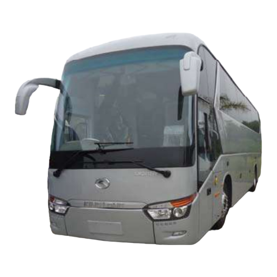
- Page 1 OPERATION MANUAL User’s Guide King-Long XMQ6129Y series tourist bus Xiamen King Long United Automotive Industry Co., Ltd. - 1 -...
-
Page 2: Foreword
As for the specifications introduced in relate to information of the driving and operation, service and maintenance of the XMQ6129Y series touring bus, please read them carefully and make proper operation, maintenance and repair so as to ensure it in good condition. -
Page 3: Table Of Contents
Contents Contents Vehicle picture--------------------------------------------------------------------------------------------------------1 Foreword---------------------------------------------------------------------------------------------------------------2 Contents Contents----------------------------------------------------------------------------------------------------------------3 Main overall technical parameters Technical parameters ------------------------------------------------------------------------------------------------7 Introduction to name plate------------------------------------------------------------------------------------------8 Product quality assurance -------------------------------------------------------------------------------------------8 Technical document -------------------------------------------------------------------------------------------------8 Vehicle body structure-----------------------------------------------------------------------------------------------9 Schematic illustration of the driver zone-------------------------------------------------------------------------10 Operation Instruction Instrument instruction------------------------------------------------------------------------------------------I-1-7 Illustration of switch and indicator s--------------------------------------------------------------------------SI-1-6 Air conditioner control panel-----------------------------------------------------------------------------------P-A-1 Pre-heater panel-----------------------------------------------------------------------------------------------P-H-1-2 Gearbox operation ---------------------------------------------------------------------------------------------O-K-1... -
Page 4: Table Of Contents
Contents Toilet system-----------------------------------------------------------------------------------------------------O-T-1 Vehicle starting and driving Check oil level of the engine--------------------------------------------------------------------------------------S-1 Check level of the coolant-----------------------------------------------------------------------------------------S-2 Check fuel pre-filter with water separator-----------------------------------------------------------------------S-3 Check fuel level-----------------------------------------------------------------------------------------------------S-4 Check vehicle lighting, intermittent lights and brake lights---------------------------------------------------S-5 Check the level of AdBlue and the daily maintenance of SCR system--------------------------------------S-7 Drain water in air tank---------------------------------------------------------------------------------------------S-8 Check engine oil pressure------------------------------------------------------------------------------------------S-9 Check Pneumatic pressure---------------------------------------------------------------------------------------S-10... -
Page 5: Table Of Contents
Contents Maintenance of engine and chassis subassembly--------------------------------------------------------------M-1 Body maintenance ------------------------------------------------------------------------------------------------M-1 ABS system maintenance and service --------------------------------------------------------------------------M-1 Electrical system maintenance and notices --------------------------------------------------------------------M-2 Tire transposition--------------------------------------------------------------------------------------------------M-2 Adjustment of the brake pedal freeplay-------------------------------------------------------------------------M-3 Bus cleaning--------------------------------------------------------------------------------------------------------M-3 Cleaning air filter --------------------------------------------------------------------------------------------------M-4 Cleaning outside of radiator -------------------------------------------------------------------------------------M-5 Coolant specification ---------------------------------------------------------------------------------------------M-5 Oil specification recommendation of the fuel and the lubricant---------------------------------------------M-6 Breaking-in of a new vehicle-------------------------------------------------------------------------------------M-9... - Page 6 Contents Air conditioner system-------------------------------------------------------------------------------------------C-18 Appendix Driver's tool table ---------------------------------------------------------------------------------------------- A-1 Tightening moment of the bolts and the nuts in major position ------------------------------------------A-2 Table of lubricant, oil & power steering oil--------------------------------------------------------------------A-3 Air braking schematic diagram (with air suspension) ------------------------------------------------------- A-4 Electrical elementary diagram of vehicle --------------------------------------------------------------------A-5 - 6 -...
-
Page 7: Technical Parameters
Technical parameter and complete vehicle description Technical parameters of the complete vehicle(DA601421-423) Product model 6129Y Engine model ISL8.9E5400 Engine type In-line six-cylinder water-cooling direct-injection diesel engine 114X144.5 (mm) Cylinder diameter× stroke (ml) 8900 Displacement 16.6:1 Compression ratio Rated capacity / rotation speed (kw/rpm) 294/2100 Max. -
Page 8: Product Quality Assurance
Technical parameter and complete vehicle description Introduction to specification data plate Bus data plate The bus data plate may be affixed to either the upside of the front passenger door frame or to the side of the front passenger door step(the position may vary with vehicle model). There are many parameters on the plate, such as vehicle model, gross mass, vehicle serial number, vehicle capacity, VIN (short for vehicle identification number), chassis serial number, engine serial number, engine model, rated power, production data and etc.. -
Page 9: Technical Document
Technical parameter and complete vehicle description Technical document The instruction book is used combined to the following specification: Engine operation instruction or service manual Air conditioner instruction book Transmission operation manual Heater instruction book CAN BUS Instrument system instruction book Monitor instruction book ABS anti-braking system instruction book VCD/DVD instruction book... - Page 10 K-1 type luggage rack, guiding seat, reversal monitor, Vehicle traveling data recorder ,reading lamp, toilet, drinking trough, color TV, DVD system, LCD, guide mike .etc. 8. Air-conditioning system Cooling system: KING LONG top mounted dependent air-conditioning system. Defroster: King Long cooling /heating defrosting device Heating system: Webasto heating system.
-
Page 11: Schematic Illustration Of The Driver Zone
Technical parameter and complete vehicle description B. Hint: Tyre TPMS a. The door remote control acts only when the parking brake is on the parking gear. b. The door could only be opened when the external mechanical lock isn't locked up. c. - Page 12 Technical parameter and complete vehicle description Instruction of instrument (VDO Edition) Function Description ABS indicator ABS work/warning High beam indicator When High beam is switched on Left turning indicator When Left turning/hazard switch is turned on Severe Error When the electrical system has severe error. (see1.1 ) General Error When the electrical system has general warning.
- Page 13 Technical parameter and complete vehicle description 1.1 Severe error conditions EDC red lamp; ECAS red lamp; EBS red lamp; coolant level low; battery not charging (after engine starts); worn brake shoes; brake circuit 1/2 pressure low; coolant temperature high; catalyst level low; engine cabin temperature high;...
- Page 14 Technical parameter and complete vehicle description pictogram comments pictogram comments Low beam working Engine amber lamp error Front fog light working Engine Malfunction Engine wait to start (do not start Rear fog light working the engine until this symbol disappear) Brake light working EBS red lamp warning Lift-axle lock...
- Page 15 Technical parameter and complete vehicle description 2.3.4 Acceleration pedal position: Range: 0 – 100 %。 2.3.5 Oil pressure: This information comes from engine ECU. Before engine starts, the value is 0. 2.3.6 Brake system pressure: Brake circuits 1 refers to the front brake system pressure. Brake circuits 2 refers to the rear brake system pressure.
- Page 16 Technical parameter and complete vehicle description If there is error exists, this page will show after driving information page when you press the page change button. Description: Pictogram :object name; Text: detailed description of the error; Errors can be displayed in this page: ...
- Page 17 Technical parameter and complete vehicle description Air conditioner status This page will appear is air conditioner is working and the communication is right. A/C mode include: ventilation; heating; cooling; demist/defrost; auto mode; off Set temp: the temperature currently set to be; Room temp: the real ambient temperature in the bus;...
- Page 18 Technical parameter and complete vehicle description Beeper warning conditions Brake circuit 1 pressure low Brake circuit 2 pressure low Coolant level low Hammer not at right position Engine cabin temperature high Oil pressure low (after engine running) ...
- Page 19 Technical parameter and complete vehicle description Illustration of switch and indicator Number of switches and indicators and position may vary with vehicle model, please consult the flowing sheet and use correctly according to actual condition of vehicle. Switch Name Color Function Notes Pressed on top: retarder is turned ON...
- Page 20 Technical parameter and complete vehicle description Switch Name Color Function Notes Pressed on top: air horn is active, Pressed on horn Green bottom: electric horn is active Pressed on top: engine idle speed raise, adjust engine Engine idle Green Pressed on bottom: engine idle speed lower speed press button once to open front passenger Front passenger door...
- Page 21 Technical parameter and complete vehicle description Switch Name Color Function Notes Pressed on top: turn on guidepost lamp; Exterior guidepost Pressed on bottom: turn off guidepost lamp Pressed on top: turn on assistant brake; only switch on when Assistant brake Yellow Pressed on bottom: to turn it off vehicle need park...
- Page 22 Technical parameter and complete vehicle description Switch Name Color Function Notes Pressed on top: open the right side bin gate; Right side bin gate Green Pressed on bottom: close the right side bin gate. Pressed on top: turn on powerful function; Powerful/abstemious Pressed on bottom: turn off abstemious transfer switch...
- Page 23 Technical parameter and complete vehicle description Color Indicator lamp Function passenger door open indicating natural gas leakage indicating front passenger door open indicate rear passenger door open indicating exit has been open indicating hollow plate Yellow ECAS alarm indicating ECAS fault indicating gearbox fault warning indicating Green retarder indicating...
- Page 24 Technical parameter and complete vehicle description Color Indicator lamp Function Transmission oil temperature too high Transmission fault White Start-up waiting Yellow Over emission Yellow Kneeling lamp Green Normal height SI-6...
- Page 25 Technical parameter and complete vehicle description Air conditioner control panel (SK-17-1) Air conditioner (KL-XIY-J) Select key introduction: Power key Indicator light introduction: Select ensure key low air speed midterm air speed Air speed select key high air speed Fresh air select key Cooling Setting Temp Up key...
- Page 26 Technical parameter and complete vehicle description 3) Temperature controlling For example: adjust the set temperature from 25 ℃ regulation A U T O Displaying the Press Press once temperature inside again the bus from the LCD screen Automatic setting after 5 seconds display the setting temperature 20℃...
- Page 27 Technical parameter and complete vehicle description Low air flow rate: the temperature of air-return inside the bus is lower than 24 ℃ (including 24 ℃ When switching air flow rate by different temperature, the switching confirm time is 30 seconds. 7) Temperature control method Using ON/OFF mode:the temperature controlling precision (DIF)is 2℃,(FIX...
- Page 28 Technical parameter and complete vehicle description 11) The part below the LCD screen will flash when the defrosting function working. A U T O 2 5 . 5 . D is p la y t h e d e f r o s t in g te m p e r a t u r e Note:...
- Page 29 Technical parameter and complete vehicle description red line voltage of control panel. Press the ,it shows the voltage of air conditioner generator(when the air conditioner is without generator, it only shows the red line voltage of control panel i.e. the voltage of vehicle generator.)If it isn't operation during this process, it will show the air return temperature after 5 seconds.
- Page 30 Technical parameter and complete vehicle description Pre-heater Operation (Webasto) Standard Timer 1. General The standard digital timer enables you to preset the start of the heater operation up to 7 days in advance. It is possible to program 3 different starting times, only one of which can be activated.
- Page 31 Technical parameter and complete vehicle description Press the 7 button – the memory location is flashing – using the 9 and 10 buttons set start of the heater operating time. Day of the week is flashing- set the day of the week. By repeatedly pressing the 6 button, memory locations 2 and 3 can be programmed or the time display mode can be reached.
-
Page 32: Gearbox Operation
Technical parameter and complete vehicle description ZF ASTRONIC Gearbox Operation description NOTE Some deviations from the operating elements and processes may occur depending on the manufacturer and vehicle type. Therefore, also consult the vehicle manufacturer’s operating manual. DANGER ! The driver must not leave the vehicle when the engine is running and a gear is selected. - Page 33 Technical parameter and complete vehicle description display, transmission is in neutral setting NOTE Gear shifts are not possible when the engine is at a stand-still. 1.2 Setting off, forwards travel Start the engine (see 2.1). Turn rotary switch from «...
- Page 34 Technical parameter and complete vehicle description Press tip lever in the « + » or « – » direction. The display shows the starting gear selected. Range selector 1.3 Manoeuvring 1st gear (depending on vehicle, 1st and 2nd gear) and R gear are provided as manoeuvring gears for extremely slow travel.
- Page 35 Technical parameter and complete vehicle description 1.4 Starting to roll on slopes Precondition: the engine must be running DANGER ! If the vehicle starts to roll and no gears are selected – rotary switch pointing to « N » – the engine brake is ineffective.
- Page 36 Technical parameter and complete vehicle description 1.6 Changing gear 1.6.1 Changing gear in automatic mode All upshifts and downshifts are performed automatically. These depend on: ➢ drive situation ➢ loading ➢ accelerator position ➢ road speed ➢ engine speed 2 arrows and 4 bars = automatic mode;...
- Page 37 Technical parameter and complete vehicle description direction required. Jumping two gears: Three times in rapid succession, push tip lever in the direction required. NOTES ➢ You can use the rotary switch to shift from any gear to neutral at any time. This shift process always takes priority.
- Page 38 Technical parameter and complete vehicle description Turn rotary switch to « R ». « R » appears in the display (clutch remains separated (disengaged)). Depress accelerator and at the same time, release brake (clutch closes automatically). Vehicle moves backwards. DANGER ! If the vehicle is rolling, shifts cannot be made into reverse!
- Page 39 Technical parameter and complete vehicle description 1.9 Stopping vehicle Do not actuate the accelerator and use the service brake to bring the vehicle to a standstill. The clutch opens automatically before the vehicle reaches a standstill so that engine “stalling” is prevented.
- Page 40 Technical parameter and complete vehicle description when towing. CAUTION For towing purposes, always disconnect the propeller shaft flange from the rear axle before setting off. If it cannot be disconnected, remove both stub shafts. Avoid polluting the environment in the event of oil loss. 1.12 Tow-starting The engine cannot be tow-started.
- Page 41 Technical parameter and complete vehicle description 1.14.2 Automatic mode DANGER ! The vehicle may accelerate on downhill slopes. The system will undertake an upshift to protect the engine from damage caused by over speeding (red range) 1.15 Roller test rig ...
- Page 42 Technical parameter and complete vehicle description ◆ Manual mode 8th gear is selected in transmission. ◆ Downshifts of up to 3 gear stages possible (one gear per bar) ◆ Transmission in neutral position ◆ Reverse gear of the transmission is engaged.
- Page 43 Technical parameter and complete vehicle description system error. The vehicle cannot be driven. « CL » = clutch ◆ Alternates with the normal display. ◆ Clutch is overloaded. Remedy: chapter 2.13 clutch protection ◆ « CW » = clutch wear ◆...
- Page 44 Technical parameter and complete vehicle description When certain system errors occur, automatic mode is deactivated and the transmission system remains in manual mode. « STOP » + « Spanner » = serious system error Stop the vehicle. Vehicle may no longer ◆...
- Page 45 Technical parameter and complete vehicle description Depending on the version, a 2 or 3-digit error number appears on the display. This corresponds to the error currently in place. If 4 bars are displayed in addition to the number, this means: error no. + 100 (only applies to two-digit displays).
- Page 46 Technical parameter and complete vehicle description ◆ At outside temperatures of below –20 °C and –30 °C, the transmission will require a warming up phase once the engine is started. The engine must be operated for at least 10 minutes with the vehicle at a standstill until the transmission oil has warmed up.
- Page 47 Technical parameter and complete vehicle description TPMS OPERATION 0-T-1...
- Page 48 Technical parameter and complete vehicle description 0-T-1...
- Page 49 Technical parameter and complete vehicle description 0-T-1...
- Page 50 Technical parameter and complete vehicle description 0-T-1...
- Page 51 Technical parameter and complete vehicle description 0-T-1...
- Page 52 Technical parameter and complete vehicle description 0-T-1...
- Page 53 Technical parameter and complete vehicle description 0-T-1...
- Page 54 Technical parameter and complete vehicle description 0-T-1...
- Page 55 Technical parameter and complete vehicle description 0-T-1...
- Page 56 Technical parameter and complete vehicle description 0-T-1...
- Page 57 Technical parameter and complete vehicle description 0-T-1...
- Page 58 Technical parameter and complete vehicle description TOILET OPERATION 一 (1). Functions and Operations ①.When using the toilet, please lock the door to ensure the system is functioning properly. ②.Occupied Light: This indication light is controller by the toilet door lock. It can probably be installed on the door of the toilet module, or be located at the front of the Coach.
- Page 59 Technical parameter and complete vehicle description ④. Hand Wash System: The toilet is Faucet Soap dispenser equipped with a water pump for the hand wash faucet. When the button is pushed, the water Hand-wash pump is turned on for a certain period of time button (normally 3-5 seconds).
- Page 60 Technical parameter and complete vehicle description ⑨. Fresh -Water Holding Tank System: The holding tank is to store the fresh water for toilet flush and hand wash, please check the water level before use. Make sure water is full. If the Water Level Warning System indicates lack of water, please watering in time.
- Page 61 Technical parameter and complete vehicle description ⑤. When clean the inside of the toilet module, remove the cover of the floor drainage. The water can be drained directly out of the coach through the floor drain. Please do not spray water at the electrical junction box, the fan, and other electrical equipment to Drainage avoid wetting them and resulting in damage.
- Page 62 Technical parameter and complete vehicle description Open/close the passage door. 1. Before leaving the vehicle, press the button 1 of the door remote controller to close the door. 2. Use the key to lock the door. First insert key into the hole 3 and clockwise rotate key about 90°, then anticlockwise rotate handle 4, after that the door would be locked.
- Page 63 Technical parameter and complete vehicle description Lock 2 Lock 3 Lock1 0-K-1...
- Page 64 Technical parameter and complete vehicle description Door remote controller 1 Door remote controller 2 Door emergency switch Model 1 The model 1 door emergency switch is located on right underside of the ingress. The model 2 door emergency switch is located on right upside of the door.
- Page 65 Technical parameter and complete vehicle description Adjustment of the driver's seat The driver's seat may be made proper adjustment for the back and forth as well as the backrest angle according to requirement of the driver. Handle 1 and Handle 2: cushion angle adjustment Handle 3: back and forth adjustment Handle 4: adjustment of the driver’s weight Left handle: backrest angle adjustment...
-
Page 66: Horn Button
Technical parameter and complete vehicle description Horn button Model 1 It is on the steering wheel. The horn is hooting when pressing the button 1. The type of steering wheel may vary with vehicle model. Please use the horn only when strictly necessary to warn other drivers and pedestrians. -
Page 67: Adjustment Of The Steering Wheel
Technical parameter and complete vehicle description Adjustment of the steering wheel Pull-up the loosening handle 1 or rotate the loosening button 2. Adjust the height and the inclination of the steering wheel to the desired position. After adjusting, press the regulating handle or button down to lock the steering column. -
Page 68: Ignition Switch
Technical parameter and complete vehicle description Ignition switch Position of the ignition key is shown in fig.1. "K" KEY: for inserting and drawing out position of the startup key 1."L" LOCK: Insert or remove the key in this position. 2."A" ACC: Power supply of the instrument is switched on 3."O"... -
Page 69: Lamplight Operating Handles
Technical parameter and complete vehicle description Lamplight operating handles Model 1 The lamplight operating handle is located on right underside of the steering wheel, which control the front small light, headlamp, headlamp dimming, left and right steering by two different motion modes Indicating that the headlamp and the small lamp are all off. -
Page 70: Wiper Operating Handle
Technical parameter and complete vehicle description Wiper operating handle Model 1 (with retarder) The wiper operating handle is located on right underside of the steering wheel. (model 1~3) OFF Out of work INT interval wiper operation step LO Slow wiping HI Quick wiping Model 2 (with exhaust brake) The wiper operating handle is located on left underside of... -
Page 71: Passenger Control Panel
Technical parameter and complete vehicle description Passenger control panel instruction Model 4 1. air outlet 2. service button 3. reading lamp button 4. lamp 5. loudhailer 6. stop button Model 1 Model 5 Model 2 Model 6 Model 3 OI-8... -
Page 72: Safety Hatch
Technical parameter and complete vehicle description Safety hatch Model 1 The safety hatch is located on scaffold of the vehicle. Please open the safety hatch according to the above diagrammatic representation illustration escaping in case of danger. Model 2 Model 3 OI-9... -
Page 73: Safety Hammer
Technical parameter and complete vehicle description Safety hammer Model 1 The safety hammer is located on the side window. Please take down the safety hammer and break open the safety window for escaping in case of danger. Model 2 OI-10... - Page 74 Technical parameter and complete vehicle description VDO module Installation position installed the step wall behind of 1.Central control electric box driver seat installed the step wall behind of 2.Body module 1 driver seat (front control unit) installed in the air duct over the 3.Body module 2 RH /FR passenger seats (ceiling control unit)
- Page 75 Technical parameter and complete vehicle description installed in cabin box at the RH RR 4.Body module 3-4 (middle &rear control unit) installed the step wall behind of driver seat. 5.Retarder control unit installed on the wall of luggage cabin. 6.WABCO ABS control unit installed in dash board.
- Page 76 Technical parameter and complete vehicle description VDO Module function description. Part A Name: ZR 32-A Function description: It is the central computer of VDO bus CAN system. ZR 32-A can receive, transmit and deal with message from power train, cluster and nodes. It also has a few of input and output pins.
- Page 77 ACC electric power relay, air condition relay and four UPL system’s relay. Their names have been marked on the wire. The capacity and the name of fuses also could be found on the fuse box cover or the King Long Instrument Wiring Harness. 0-E-2...
-
Page 78: Switch Control Box
Technical parameter and complete vehicle description Switch control box (Model: CQ2025) CQ2025 A wiring diagram (Printed on opposite cover of the switch control box) 0-E-3... - Page 79 Technical parameter and complete vehicle description The hydraulic fan mechanism This system should be made to drive the fan’s rotation through pressure yielded from hydraulic oil. 0-E-4...
-
Page 80: Check Oil Level Of The Engine
Vehicle Starting and Driving Preparatives for vehicle operation start up: Check daily, before turning engine on: Oil level dipstick 1. Check oil level of the engine The warning “Engine oil pressure” is displayed as a signal item on the combination instrument when the oil pressure is too low, the alarm buzzer sounds, the warning light STOP comes on, stop the engine and check engine oil level at the dipstick. -
Page 81: Check Level Of The Coolant
Vehicle Starting and Driving 2 Check level of the coolant The coolant level is automatically monitored. If coolant level gets too low,the digital indicator displays a driver information on the combination instrument. In this case, park vehicle in a safe place as traffic conditions permit, stop engine and visually check the coolant level. - Page 82 Vehicle Starting and Driving 3 Fuel pre-filter with water separator (drain accumulated water) Model for Euro II Draining accumulated water On a daily basis, check the lower cup of the water separator. If there is water in the cup, unscrew the draining plug one or two turns, to drain the accumulated water.
- Page 83 Vehicle Starting and Driving 4. Fuel level Turn the ignition key to drive position (on). Check the fuel level on the indicator. If necessary, fill up the fuel tank. (but direct viewing by open the tank cover is preferred). Eliminate deposite water in diesel filter in time and check fuel pipe for no leakage.
- Page 84 Vehicle Starting and Driving 5. Vehicle lighting, intermittent lights and brake lights Check all instruments and indicator lamps for normal, especially the head lamp, the turning lamp, the brake lamp, the reversing lamp and the danger alarm lamp. Check the bulb and the switch for their damage. To carry out the lamp substitution, hands should be very clean.
-
Page 85: Check The Level Of Adblue And The Daily Maintenance Of Scr System
Vehicle Starting and Driving 6. Check the level of AdBlue and the daily maintenance of SCR system The volume of AdBlue Check the level of AdBlue. When the vehicle key rotate the ON position, the LED screen of combination instrument will display the remain volume of the AdBlue, please see the right diagram. - Page 86 Vehicle Starting and Driving If the AdBlue spill in skin, mild irritation may occur. Wash off with soap and water. If the AdBlue spill in eye, irrigate eyes with large amount of water. The AdBlue is Non-combustible, if heated water evaporates and ammonia will be released.
-
Page 87: Drain Water In Air Tank
Vehicle Starting and Driving Drain water in air tank Open the water drain valve of air tank to drain oily water fully. If too much oily water is bled, check to see if desiccant needs to be replaced in air drier. (This may be avoided when adopting the automatic drain valve but it should be checked every two weeks) - Page 88 Vehicle Starting and Driving Check daily after turning engine on: 1. engine oil pressure Run the engine. The information on engine oil pressure can be requested through the driver information digital display. If the oil pressure is too low, the oil pressure is automatically shown on the combination instrument. Indication of the oil gauge will show a high value after the cold start of the engine and then it should be kept within the range of 0.3-0.5Mpa (3- 5kg/cm ) along with the increment of the oil temperature as well...
- Page 89 Vehicle Starting and Driving 2. Pneumatic pressure The air pressure gauge indicates the reserve pressure individually for the front and rear service brake circuits. The reserve air pressure in each brake circuit must be sufficient for the correct operation of the brake system.
- Page 90 Vehicle Starting and Driving 3. Tachometer working order Indications on tachometer scale: a. Green zone – operating range of maximum performance b. Yellow zone – c. Red zone – engine overspeed range (risk of immediate engine damage) Always observe tachometer while driving the vehicle. Whenever possible keep engine running within the economical range.
-
Page 91: Steering Wheel Play
Vehicle Starting and Driving 4. Steering play Steering wheel play Run the engine at idle gear and straighten the front wheels forwards. Turn the steering wheel alternatively to the right and to the left. The steering play (free movement of the steering wheel) is measured on the perimeter of the steering wheel and should be between 20 and 30 mm. -
Page 92: Check Tire For Abrasion And Pressure And Tire Nut For Fixture
Vehicle Starting and Driving Control periodically, at least once a week: 1. Check tire for abrasion and pressure and tire nut for fixture The vehicle’s safety and performance depend considerably on the state of the tires, reason why they should be checked daily. Before driving a vehicle, check charging pressure of tire for normal, tire for damage, tire nut for fixture. -
Page 93: Air Cleaner
Vehicle Starting and Driving 2. Air cleaner (activate the dust discharge valve to loosen accumulated dust) Model 1 The maintenance of the air cleaner is made up of the substitution of the filtering elements and should be done only when the maintenance indicator indicates the saturation of the element. -
Page 94: General Leakages (Water, Oil, Fluids And Fuel)
Vehicle Starting and Driving 3. General leakages (water, oil, fluids and fuel) Check the engine, the transmission, the driving axle, the steering system, the cooling system and the oil pipeline, the air pipeline of the complete vehicle for their leakage. S-15... -
Page 95: Fastening And State Of Seat Belts
Vehicle Starting and Driving 4. Fastening and state of seat belts Check buckle of the safety belt of the driver seat for normal and ensure for its lockup under the following situations when fastening the safety belt. ● The body dashes forward all of a sudden; ●... - Page 96 Vehicle Starting and Driving 5. Check emergency devices and driver’s tools Such as extinguisher, crosstie for blocking vehicle, emergency hammer, jack and etc.. Fire extinguisher Fire extinguisher: The pulse super-micro powder fire extinguisher is fixed in the engine compartment, when the compartment is on fire, the fire extinguisher activate automatically or is active by manual work to eradicate the fire The fire button is usually located at auxiliary instrument...
-
Page 97: Windshield Wipers And Conditions Of Wiper Blades And Arms
Vehicle Starting and Driving 6. Working order of windshield wipers and conditions of wiper blades and arms Model 1 Regularly check the windshield wiper blades for dirt or damage. Press the lever to activate the windshield washer Caution: Do not use the windshield wipers when the windshield is dry. -
Page 98: Electrical Rearview Mirror
Vehicle Starting and Driving 7. Electrical rearview mirror Check, adjust and clean the rearview mirror. Model 1 Rearview mirror control button Model 1 L: adjusting left rearview mirror. R: adjusting right rearview mirror. Mirror button: push down the arrow headed button to adjust the mirror for 4 directions. -
Page 99: Power Steering System
Vehicle Starting and Driving Inspection every two weeks before and after driving Model 1 1. Power steering Ensure that all the maintenance service jobs on the steering system be carried out at the intervals recommended in the maintenance manual to guaranty total efficiency and safety. If any working abnormality in the steering is noticed, immediately supply the necessary repairs. -
Page 100: General State And Tension Of Drive Belts
Vehicle Starting and Driving 3. General state and tension of drive belts Check the tension of engine belt, fan belt and compressor belt, if loose, tension it; if damaged, replace it. Do not start up the engine without the drive belts. In the case of one of the belts breaking, immediately stop the engine and have a new belt put in. - Page 101 Vehicle Starting and Driving Air conditioning compressor drive belt The pneumatic tensioning system keeps the tension of air conditioning compressor drive belt correctly adjusted and do not need to be adjusted periodically. Adjusting method of the air conditioner belt is shown in the figure 1 Check tension of belt Apply 98N force to belt with finger Belt crank pulley 4 and middle pulley 2 should lower 10~15mm...
-
Page 102: Check Level Of Battery Electrolyte
Vehicle Starting and Driving 4. Check level of battery electrolyte Open the battery cover to check level of electrolyte, if the level is lower than scale marked on the battery, please add it in time. Note: During adding electrolyte, never start engine. Battery The battery compartment is located at the second compartment of left or right rear side. -
Page 103: Procedures For Engine Start Up
Vehicle Starting and Driving Engine start up and shut down Procedures for engine start up Activate parking brake. Place the gear box lever in neutral. Start up is not possible in gear position. Turn the ignition key into gear position. Start up without stepping on the accelerator. -
Page 104: Engine Shut Down
Vehicle Starting and Driving Engine shut down Loosen accelerator pedal. Place the gear box lever in neutral position and apply the parking brake. Turn the ignition key to the off position, without accelerating. Note: After engine runs at heavy loading, temperature of cooling water is higher than 90ºC, so do not stop engine at once. -
Page 105: Engine Start Up And Shut Down In The Engine Compartment
Vehicle Starting and Driving Engine start up and shut down in the engine compartment Park the vehicle and activate the parking brake. Model 1 Put the gear box lever or the automatic transmission selector in neutral (dead point). If the transmission is in gear position, the start up with in the engine compartment will not work. -
Page 106: Starting The Vehicle
Vehicle Starting and Driving Starting the vehicle The vehicle could only be started when braking system pressure has reached 5kg/cm above and each instrument and indicator lamp is on the proper condition, and water outlet temperature exceeds 60℃ as well as the parking brake has been released after the engine is started. -
Page 107: Parking The Vehicle
Vehicle Starting and Driving Parking the vehicle The parking brake should be always applied when the vehicle is parked. Additionally, in some countries, it is determined by law that a vehicle parked on a slope must have at least one of its wheels wedged, to prevent its accidental moving. In this case, always keep an appropriate wedge available for this purpose aboard the vehicle. -
Page 108: General Knowledge
Maintenance and service General knowledge KingLong recommends that the bus be maintained according to the Maintenance Schedule in this section. Perform maintenance at whichever interval occurs first. At each scheduled maintenance interval, perform all previous maintenance checks they are due for scheduled maintenance. King-long Bus General Maintenance Please make periodic inspection and maintenance of bus according to the operation manual to ensure good status. -
Page 109: Tire Transposition
Maintenance and service When maintain the brake shoe ,do not damage the ring gear and sensor, clean the ring gear and sensor at the same time. after maintenance ,do remember to put the sensor to the limited position along the ring gear direction. Make sure that the power is in off position when remove and install the components, keep the components clean and dry. -
Page 110: Bus Cleaning
Maintenance and service Tire transposition diagram(three axles) Adjustment of the brake pedal free play Loosen locknut of brake pedal push rod and adjust adjusting nut, and then measure the vertical distance from pedal free position to the position where pressing resistance increases apparently when depressing pedal. - Page 111 Maintenance and service Cleaning the air filter Hint: Please replace filter element under such conditions: it has been washed 5 times; filter element has been damaged; filter element is clogged excessively; after changing the engine oil .When air filter indicator on combination instrument lights, clean the air filter or replace the element.
- Page 112 Maintenance and service Caution: Vapor spray gun, solution, gasoline or equivalent should not be used during the cleaning. -Before reinstalling air filter element, check element from inside to outside with check lamp for damage; -Check sealing ring for damage or cracks. Caution: Do not start the engine without mounting the air filter.
-
Page 113: Coolant Specification
Maintenance and service below: mix 700-800g caustic soda with 150g kerosene and then inject the miscible liquids into water, at this time, make engine run at middle speed for 5-10 minutes. 10-12 hours later, make engine run again for 10-15 minutes and then drain aqueous solution and clean cooling system with fresh water. Coolant specification as shown below: the users should choose proper brand according to requirement: Specs ℃... - Page 114 Maintenance and service Engine oil viscosity Since oil viscosity fluctuated with temperature, so the ambient temperature of engine working area is very important to select viscosity grade (as shown in the figure). When temperature exceed lower limit, it may decrease cold start capacity of the engine but will not make any damage to the engine. ...
- Page 115 Maintenance and service Power steering hydraulic oil: Fulfill standard: Generai Allison C-3. When ambient temperature is low than 10°C, please apply DEXRON-II hydraulic fluid to steering gear; when ambient temperature is higher than 10°C, please apply C-3/10W hydraulic fluid. C-3/10W grade oil can be used in most area .all-year generally. C-3/30 grade oil can be used in non-cold area all-year generally.
- Page 116 Maintenance and service Breaking-in of New Vehicle Engine of new vehicle should be sure not to operate at the maximum power output during the breaking-in period to keep best performance and superior efficiency as well as guarantee durable service life. Please drive cautiously and pay more attention to abnormal phenomenon occurred during breaking-in period.
- Page 117 Maintenance and service 6. Check connection of transmission control mechanism for looseness. 7. Check connections of steering gear for looseness and damage. 8. Tighten bolts and nuts of front and rear suspension(carry out when full load) 9. Check connections of chassis and driving system according to specified torques. Tighten torques please refer to corresponding instructions.
- Page 118 Maintenance and service Daily or Refueling Maintenance Check System Item Operation Technical requirement No leakage, damage, and crack. Air cleaner Check Clips without looseness. Fuel-water Release the water and fouling Drain separator Do not pull or lever the cooling fan for starting the engine. Cooling fan Inspect No crack, looseness, bend or damage.
- Page 119 Maintenance and service Periodical maintenance and operation items and regulations Periodical maintenance of each class: do maintenance during each interval or certain miles . Special instruction: if assembly instruction requires different oil replace period, please follow the instruction’s requirement on maintenance period and operation. If else please refer to this manual for maintenance requirement.
- Page 120 Maintenance and service System Item Operation Technical requirement Rear axle housing and differential housing, rear Check & fasten axle housing rear cover half axle bolts and nuts, Rear axle ( DF & No loosen Fastening Check & piece adjust FS series) Ventilate Clean stopper...
- Page 121 Maintenance and service System Item Operation Technical requirement Front axle Brake clearance Check & ( DF & FS adjust series) Rear axle Brake clearance Check & ( DF & FS adjust series) Fasteners Check/tighten Check and tighten the bolts, rods, height control suspension valves, air springs, shock absorbers, anti-roll bars.
- Page 122 Maintenance and service System Item Operation Technical requirement brake pedal Check & 10-15mm free stroke adjust Shoe drum clearance: 0.30mm ~ 0.50mm, in braking Check condition complete braking, pedal stroke not surpass 1/2 of the whole stroke, check dry tin condition Brake brake Check...
- Page 123 Maintenance and service Maintenance operation and regulation every 10000km or 3 months Every 10000km include every 5000km maintenance operation System Item Operation Technical requirement Replace Check oil surface within required range Check engine and oil seal without apparent leakage Replace oil when engine water temperature is 60 , ℃...
- Page 124 Maintenance and service Maintenance operation and regulation every 20000km or 5 months depend on what occurs first. Every 20000km include every 10000km maintenance operation System Item Operation Technical requirement Fuel filter Replace Replace fuel filter element accordingly Steering hydraulic Replace Steering auxiliary oil surface within required range Engine Coolant system –...
- Page 125 Maintenance and service System Item Operation Technical requirement There are gaps on the surface of the rubber The surface of the rubber become adhesive, brittle and the rubbe drop off seriously The rubber bal Change The connection of the metal and the rubber is damaged. The partia joints depth is up to 6mm The rubber ball joint rotates in the inner hole of the ball head a...
- Page 126 Maintenance and service System Item Operation Technical requirement front rear wind shield and Check Clean, no crack, sealing good side window glass clean Body paint no crack or peeling, re-paint color the body with paint Check same as original Body, frame pattern, character, company Check Pattern, character, company mark clear, complete...
- Page 127 Maintenance and service Maintenance operation and regulation every 40000km or 8 months depend on what occurs first. Every 40000km include every 20000km maintenance operation System Item Operation Technical requirement Drive belt, Cooling fan belt tension Check/adjust Check each belt without loosening or damage Cooling fan bearing and bolt Check/adjust No damage, fouling, loosening Engine...
- Page 128 Maintenance and service Maintenance operation and regulation more than 80000km ZF Series axle Oil or Grease change required, depending on what occurs first. Products Model Maintenance content Maintenance Oil class Remark name interval Filling-up 80,000-90,000KM or NLGI Class 2 grease(lubricant point) 1 year check-up oil level and 90,000~120,000KM...
-
Page 129: Maintenance Period Chart
Maintenance and service Maintenance period chart 1、1st line is the item of break-in of new vehicle (prescript items completed after driving 2500KM or the day of registration vehicle) 2、Other items are compulsion maintenance program (the circulation is 80000KM/12 months) 3、 For engine、 axle、 transmission please refer to producer’s maintenance manual, if without special maintenance period, please refer to this manual for maintenance information. -
Page 130: Clutch
Maintenance and service Maintenance period chart 1、1st line is the item of break-in of new vehicle (prescript items completed after driving 2500KM or the day of registration vehicle) 2、Other items are compulsion maintenance program (the circulation is 80000KM/12 months) 3、For engine、axle、transmission please refer to producer’s maintenance manual, if without special maintenance period, please refer to this manual for maintenance information. - Page 131 Maintenance and service Maintenance period chart 1、1st line is the item of break-in of new vehicle (prescript items completed after driving 2500KM or the day of registration vehicle) 2、Other items are compulsion maintenance program (the circulation is 80000KM/12 months) 3、For engine、axle、transmission please refer to producer’s maintenance manual, if without special maintenance period, please refer to this manual for maintenance information.
- Page 132 Maintenance and service Maintenance period chart 1、1st line is the item of break-in of new vehicle (prescript items completed after driving 2500KM or the day of registration vehicle) 2、Other items are compulsion maintenance program (the circulation is 80000KM/12 months) 3、For engine、axle、transmission please refer to producer’s maintenance manual, if without special maintenance period, please refer to this manual for maintenance information.
- Page 133 Common trouble and elimination Maintenance period chart 1、1st line is the item of break-in of new vehicle (prescript items completed after driving 2500KM or the day of registration vehicle) 2、Other items are compulsion maintenance program (the circulation is 80000KM/12 months) 3、For engine、axle、transmission please refer to producer’s maintenance manual, if without special maintenance period, please refer to this manual for maintenance information.
- Page 134 Common trouble and elimination Engine common trouble and its elimination (suitable for diesel engine) Diesel engine can not start Possible causes Remedies 1 ) Too low starting speed 1) Check the starting system and assure the starting speed is not lower than 110rpm.
- Page 135 Common trouble and elimination Diesel engine power deficient Possible causes Remedies 1 ) Intake blocked 1 ) Check the air cleaner, intake pipe, and clean or replace the air cleaner filter elements. 2 ) high exhaust back pressure 2 ) Check the valve timing, adjust it if necessary; Clean the exhaust pipe.
- Page 136 Common trouble and elimination Abnormal noise during engine operation Possible causes Remedies 1) Connecting rod bearing bushing and 1) Dismantle and check the bushing and, if necessary, replace it main bearing bushing are worn-out and keep the reasonable clearance as required. and clash voice appears in the crankcase.
- Page 137 Common trouble and elimination Exhaust with black smoke Possible causes Remedies 1) Intake clogged 1) heck and clean the air cleaner and intake passage. 2) Poor fuel quality 2) Use prescribed fuel. 3) Incorrect distribution timing 3) Adjust the distribution timing according to the instruction. 4) Bad atomization of injector 4) Check and repair or replace 5) The injector spray too much fuel...
- Page 138 Common trouble and elimination Too low oil pressure Possible causes Remedies 1) Diluted or incorrectly selected 1) Select the proper oil. 2) Inner and outer rotors of oil pump worn-out 2) Replace the oil pump. or too large 3) Oil filter choked 3) Replace the whirling type filter element.
-
Page 139: Propeller Shaft
Common trouble and elimination Chassis constant fault and elimination Propeller shaft Fault Possible cause Eliminating method symptom Propeller shaft sliding yoke Remove and let the sliding yoke and the assembled incorrectly fixing yoke on the same plane The propeller shaft is distortion or Adjust or replace the propeller shaft bending The universal-joint journal or the... -
Page 140: Transmission
Common trouble and elimination Transmission Fault Possible cause Eliminating method symptom Control mechanism 1) Improper height of the control hinge 1) Adjust the control hinge 2) There has clearance between the 2) Correct or replace the parts control hinge connection 3) The control hinge bend 3)... -
Page 141: Rear Axle
Common trouble and elimination Rear axle Fault Possible cause Eliminating method symptom When the vehicle is starting Excessive clearance between 1) Adjust the clearance the differential gear Excessive clearance between 2) Adjust the clearance the driving and the driven gear Looseness of the connecting 3)... -
Page 142: Front Axle And Steering System
Common trouble and elimination Fault Possible cause Eliminating method symptom Blocking or damage of the Clean or replace the ventilation ventilation plug plug Axle housing cracks Leakage of Damage distortion Repair or replace the axle housing the rear coupling flange sealing surface Adjust or replace the coupling axle Malfunction of bearing leads to... - Page 143 Common trouble and elimination Fault Possible cause Eliminating method symptom 6) Fatigue of the front leaf spring, 6) Replace the faulted parts looseness of the "U" -bolt or damage of the central bolt The steering system 1) Difficulty gear 1) Adjust the gear engagement engagement 2)...
- Page 144 Common trouble and elimination Fault Possible cause Eliminating method symptom Others 1) Correct the driving pattern Misproportion 1) Breakdown caused untimely abrupt starting or the emergent 2) Make the loading according to the tire wear braking specified capacity 2) Overloading Too low oil level Add the lubricant to the given Lubricant...
-
Page 145: Braking System
Common trouble and elimination There has oil Clogging of the strainer or the Clean the filter strainer or replace spillage in the filter element the filter element steering oil There has air in the pipeline Add the oil and make the tank exhaustion Braking system... - Page 146 Common trouble and elimination Fault Possible cause Eliminating method symptom Tire pressure uneven or tire Operate as required dimension different Improper installation of the Tighten the locknut of the brake brake shoe or damage of the shoe supporting pin and replace the return spring return spring Improper engagement of the...
- Page 147 Common trouble and elimination Fault Possible cause Eliminating method symptom When compressed air pressure is abnormal: Repair the leakage point There has air leakage inside the air pipeline Disassemble repair The air compressor doesn't compressor work Adjust or wash pressure regulator Disassemble and repair the brake improper adjusted or failured...
- Page 148 Common trouble and elimination Fault Possible cause Eliminating method symptom The battery has no power, or is Charge and clean the joint and lack of power or terminal loose screw it Poor contact of the starter switch, short circuit of the Repair or replace it connector lug or bad of the solenoid...
-
Page 149: Air Conditioner System
Common trouble and elimination Common trouble and troubleshooting of air conditioner system The remedy and trouble analysis under abnormal pressure Pressure Description Analysis Remedy There is bubble in the inspection glass ; the Check cold air in the bus system for the The refrigerant insufficient high... - Page 150 Common trouble and elimination Pressure Description Analysis Remedy Discharge the Air mixed in the refrigerant in The high and low The cooling capability refrigerant the system pressure are vacuum is not and change much higher than Insufficient good for the first the desiccators the normal value system has air and the...
- Page 151 Common trouble and elimination Electric system trouble and remedy Fault Possible cause Eliminating method symptom the power 1. + no power supply; generator D+ no output, exchange lamp on the the generator and repair control 2. D+ not connected well; reconnect the cable D+;...
- Page 152 Common trouble and elimination Fault Possible cause Eliminating method symptom compressor clutch connecting cable reconnect the cable; not connected well; change the clutch or repair; clutch damaged; refer to the above-mentioned items; compressor malfunction lamp light up; not working refrigerant light not lighting up; relay out of work;...
- Page 153 Appendix Driver tools table(one each) Part name Part name Tool box Flat-tip screwdriver 6*100MM Combination wrench 8 Hammer 1 pound Combination wrench 10 Slip joint pliers 8” Combination wrench 12 Nipper pliers 6” Combination wrench 13 Tire pressure gauge 0-1.4MPa Combination wrench 14 Valve core wrench Combination wrench 15...
- Page 154 Appendix Tightening torque of main bolts and nuts Position Tightening torque(N·m) Front tyre nut 412~480 Rear tyre nut 294~421 Bolt, connecting lower knuckle and ball pin 245~304 Steering kingpin lockpin nut 60~70 Fixing nut, upper steering knuckle 274~343 Binding nut, tie rod 90~110 Locked bolt and nut between pitman arm and pitman arm shaft 407~434...
- Page 155 Appendix Bolts torque table Torques for bolts with metric unified threads Torques N.m*(ft-lb) Dimension of bolt 10.9 12.9 3(2) 5(3) 5(4) 6(4) 9(7) 10(7) 10(7) 15(11) 18(13) 25(18) 35(26) 45(33) 50(37) 75(55) 83(61) 88(65) 123(91) 147(108) 137(101) 196(145) 235(173) 211(156) 300(221) 358(264) 290(213)
- Page 156 Appendix The table of Lubricant, Power steering oil and Grease Main assembly lubricant Oil site Lubricant Type/table Level/type Engine Diesel engine oil 15W/40 API CH – 4/SG Transmission Gear oil TM-ML02 Ecofluid M Main reducer Gear oil TE-ML12 Ecofluid X Explanation :1) Diesel engine oil--API CH -4/SG ,15W/40 , be used upwards -10℃...
- Page 157 Appendix Air braking schematic diagram...
- Page 158 Appendix Electric schematic diagram of the complete vehicle (1)
- Page 159 Appendix Electric schematic diagram of the complete vehicle (2)...
- Page 160 Appendix Electric schematic diagram of the complete vehicle (3)
- Page 161 Appendix Electric schematic diagram of the complete vehicle (4)
Need help?
Do you have a question about the XMQ6129Y series and is the answer not in the manual?
Questions and answers