
Related Manuals for Bender PEM353


Summary of Contents for Bender PEM353
- Page 1 Manual PEM353 Universal measuring device Software version: 1.00.00 Hardware version: 1.00 PEM353_D00335_00_M_XXEN/06.2018...
- Page 2 Bender GmbH & Co. KG Londorfer Str. 65 • 35305 Gruenberg • Germany Postfach 1161 • 35301 Gruenberg • Germany Tel.: +49 6401 807-0 • Fax: +49 6401 807-259 E-Mail: info@bender.de • www.bender.de © Bender GmbH & Co. KG All rights reserved.
-
Page 3: Table Of Contents
3. Device description ................15 Scope of delivery ..................... 15 Product description ..................15 Areas of application ..................15 Functions ......................16 Compatibility with Bender Gateways ............18 Variants ....................... 19 Application example ..................20 4. Installation .................... 21 Dimension diagram ..................21 Mounting in a front panel ................ - Page 4 Table of Contents Removing from a front panel ..............22 5. Connection ..................23 Overview of the terminals ................24 Overview of the wiring diagrams .............. 25 Wiring diagrams direct connection (without potential transformers) 26 5.3.1 1P2W L-N ......................26 5.3.2 1P2W L-L ......................
- Page 5 Table of Contents Navigation ......................40 Standard display ....................41 Data display ....................... 41 7.5.1 Detail page "U/I" ....................41 7.5.2 Detail page "Power" ..................43 7.5.3 Detail page "Energy" ..................43 7.5.4 Detail page "Demand" ................... 44 7.5.5 Detail page "Harmonics" ................45 7.5.6 Detail page "Max./Min."...
- Page 6 Table of Contents 12.3 Unbalance ......................72 13. Setpoints ....................73 14. Log ......................77 14.1 Max./Min. log ....................77 14.2 Peak demand log ..................... 79 14.3 Monthly energy log ..................80 14.4 Event log (SOE log) ..................81 15. Time of Use (TOU) ................83 15.1 Tariff switch according to a fixed schedule ..........
- Page 7 16.18 Event log (SOE log) ..................134 16.19 DOx control ..................... 143 16.20 Universal measuring device information ..........144 17. PEM353-N ..................147 17.1 Daily and monthly logs (freeze logs) ............. 147 17.1.1 Daily freeze log ....................147 17.1.2 Monthly freeze log ..................149 17.2...
-
Page 9: Important Information
1. Important information 1.1 How to use this manual This manual is intended for qualified personnel working in electrical engineering and electronics! Always keep this manual within easy reach for future reference. To make it easier for you to understand and revisit certain sections in this manual, we have used symbols to identify important instructions and information. -
Page 10: Technical Support: Service And Support
Repair, calibration, testing and analysing Bender products Hardware and software update for Bender devices Delivery of replacement devices for faulty or incorrectly delivered Bender devices Extended warranty for Bender devices with in-house repair service resp. replace- ... -
Page 11: Training Courses
ZVEI (Zentralverband Elektrotechnik- und Elektronikindustrie e.V., (German Elec- trical and Electronic Manufacturers' Association) also applies. Conditions of sale and delivery can be obtained from Bender in printed or electronic for- mat. 1.5 Inspection, transport and storage Inspect the packaging and equipment packaging for damage, and compare the con- tents of the package with the delivery documents. -
Page 12: Warranty And Liability
13th August 2005 must be taken back by the manufacturer and disposed of properly. For more information on the disposal of Bender devices, refer to our website at www.bender-de.com -> Service & support. -
Page 13: Safety Instructions
2.1 General safety instructions Part of the device documentation in addition to this manual is the enclosed " Safety in- structions for Bender products". 2.2 Work on electrical installations Only qualified personnel are permitted to carry out the work necessary to install, commission and run a device or system. -
Page 14: Intended Use
Safety instructions 2.3 Intended use The PEM353 is suitable for use in 2-, 3- and 4-wire systems and in their respective ver- sions as TN, TT and IT systems. The current measurement inputs of the PEM353 are always connected via external …/ 1 A or …/5 A measuring current transformers. -
Page 15: Device Description
THD and the individual harmonics up to the 31st order. The PEM353 is suitable for use in 2-, 3- and 4-wire systems and in their respective ver- sions as TN, TT and IT systems. This allows monitoring single and polyphase systems. -
Page 16: Functions
Accuracy class of the active energy acc. to IEC 62053-22: 0.5 S LED (pulse) for active or reactive energy 2 pulse outputs (PEM353-P only) Total phase and individual phase energy metering – Import, export, net and total per active and reactive energy –... - Page 17 System messages Limit value violations 9. Load data log: daily and monthly values (PEM353-N only) Daily log – 60 days (2 months) – Total phase energy per active, reactive and apparent energy –...
-
Page 18: Compatibility With Bender Gateways
For further information on Bender Gateways, please refer to our homepage. Whether the PEM353 is supported by a Bender Gateway depends on the respective firmware version. You can find a compatibility list on our homepage. -
Page 19: Variants
Device description 3.6 Variants Property PEM353 PEM353-P PEM353-N Voltage inputs (L1, L2, L3) AC 230/400 V; 45…65 Hz Supply voltage 95…250 V; DC, AC 47…440 Hz Digital inputs 2 solid-state pulse Digital outputs 2 relay outputs 2 relay outputs outputs... -
Page 20: Application Example
Device description 3.7 Application example PEM7xx PEM7xx Ethernet Datenbank Modbus TCP Modbus TCP NSHV CP700 COM465IP COM465DP 1…12 PEM5xx PEM5xx Modbus RCMS 1…12 Modbus TCP Modbus TCP Modbus RTU Modbus RTU RCMS PEM3xx PEM3xx Modbus RTU Modbus RTU Fig. 3.1: Application example PEM353_D00335_00_M_XXEN/06.2018... -
Page 21: Installation
Observe the rules for working on electrical installations. Refer to the rated and supply voltage values as specified in the technical data! 4.1 Dimension diagram The dimensions comply with DIN lEC 61554:2002-08 13.2 47.3 91.5 91.5 Fig. 4.1: Dimension diagram PEM353 PEM353_D00335_00_M_XXEN/06.2018... -
Page 22: Mounting In A Front Panel
Installation Fig. 4.2: Dimension diagram PEM353 (panel cutout) 4.2 Mounting in a front panel Provide a mounting opening of 92 mm x 92 mm (max. permissible dimensions 92.8 x 92.8 mm). Consider the mounting depth of the device and the space required for terminal connection. -
Page 23: Connection
5. Connection Only qualified personnel working in electrical engineering and electronics are permitted to carry out the work necessary to install, commission and run a device or system. Risk of fatal injury due to electric shock! Touching live parts of the system carries the risk of: An electric shock ... -
Page 24: Overview Of The Terminals
DO13 DO14 DO23 DO24 PEM353(-N) PEM353-P Fig. 5.1: Wiring diagram PEM353 Legend to wiring diagram PEM353 Measuring voltage inputs: The measuring leads should be protected with appropriate fuses. Supply voltage: Power protection by a quick-response 6 A fuse. If supplied from an IT system, both lines must be protected by a fuse. -
Page 25: Overview Of The Wiring Diagrams
Connection 5.2 Overview of the wiring diagrams The following connection configurations are supported: Direct connection (without potential transformers) 1P2W LN 1P2W LL 1P3W 3P3W with 3 measuring current transformers 3P3W with 2 measuring current transformers (Aron) ... -
Page 26: Wiring Diagrams Direct Connection (Without Potential Transformers)
Connection 5.3 Wiring diagrams direct connection (without potential trans- formers) 5.3.1 1P2W L-N Source Load Fig. 5.2: Connection diagram one-phase 2-wire system Disconnect terminal of the measuring current transformers When using this wiring, the wiring mode (Setup > Basic > Wiring Mode) must be set to 1P2W L-N. -
Page 27: 1P2W L-L
Connection 5.3.2 1P2W L-L Source Load Fig. 5.3: Connection diagram one-phase 2-wire system Disconnect terminal of the measuring current transformers When using this wiring, the wiring mode (Setup > Basic > Wiring Mode) must be set to 1P2W L-L. PEM353_D00335_00_M_XXEN/06.2018... -
Page 28: 1P3W With 2 Measuring Current Transformers
Connection 5.3.3 1P3W with 2 measuring current transformers Source Load Fig. 5.4: Connection diagram one-phase 3-wire system Disconnect terminal of the measuring current transformers When used in a 3-wire system, the wiring mode (Setup > Basic > Wiring Mode) must be set to 1P3W. PEM353_D00335_00_M_XXEN/06.2018... -
Page 29: 3P3W With 3 Measuring Current Transformers
Connection 5.3.4 3P3W with 3 measuring current transformers Source Load Fig. 5.5: Connection diagram with 3 measuring current transformers Disconnect terminal of the measuring current transformers When used in a 3-wire system, the wiring mode (Setup > Basic > Wiring Mode) must be set to 3P3W. -
Page 30: 3P3W With 2 Measuring Current Transformers (Aron Circuit)
Connection 5.3.5 3P3W with 2 measuring current transformers (Aron circuit) Source Load Fig. 5.6: Connection diagram 3P3W with 2 measuring current transformers (Aron circuit) Disconnect terminal of the measuring current transformers When used in a 3-wire system, the wiring mode (Setup > Basic > Wiring Mode) must be set to 3P3W. -
Page 31: 3P4W With 3 (4) Measuring Current Transformers
Fig. 5.7: Connection diagram 3P4W with 3 (4) measuring current transformers Disconnect terminal of the measuring current transformers Measurement I for PEM353-N only When using this wiring, the wiring mode (Setup > Basic > Wiring Mode) must be set to 3P4W. -
Page 32: Wiring Diagrams With Potential Transformers (Medium And High Voltage)
Load Fig. 5.8: Connection diagram three-phase 3-wire system Disconnect terminal of the measuring current transformers The transformation ratio in the PEM353 can be set by specifying the primary and secondary transformation ratio. Odd ratios can also be configured. When used in a 3-wire system, the wiring mode (Setup > Basic > Wiring Mode) must be set to 3P3W. -
Page 33: 3P4W With 3 Potential Transformers
Disconnect terminal of the measuring current transformers Measurement I for PEM353-N only The transformation ratio in the PEM353 can be set by specifying the primary and secondary transformation ratio. Odd ratios can also be configured. When using this wiring, the wiring mode (Setup > Basic > Wiring Mode) must be set to 3P4W. -
Page 34: Supply Voltage
5.5 Supply voltage Provide power protection by a quick-response 6 A fuse. Connect the PEM353 to the supply voltage (terminals A1/+ and A2/–). A single-pole supply voltage must be protected by a fuse; if the device is powered by an IT system, all poles must be protected. -
Page 35: Digital Outputs
Connection 5.10 Digital outputs PEM353(-N) features 2 configurable outputs (N/O relay), PEM353-P features 2 pulse outputs ("Solid State Relay"). Rated operational AC 250 V DC 30 V DO13 DO14 PEM353 voltage PEM353-N (2 relay contacts) Rated operational DO23 DO24 current... - Page 36 Connection PEM353_D00335_00_M_XXEN/06.2018...
-
Page 37: Commissioning
6. Commissioning Only qualified personnel are permitted to carry out the work necessary to install, commission and run a device or system. Risk of fatal injury due to electric shock! Touching live parts of the system carries the risk of: An electric shock ... -
Page 38: After Switching On (Configuration)
Commissioning 6.3 After switching on (configuration) After connecting the supply voltage, carry out at least the following steps: 1. Set language, time and date (see "chapter 8. Setup" > Clock) 2. Configure the communication interface (see "chapter 8. Setup" > Comm.) 3. -
Page 39: Operation
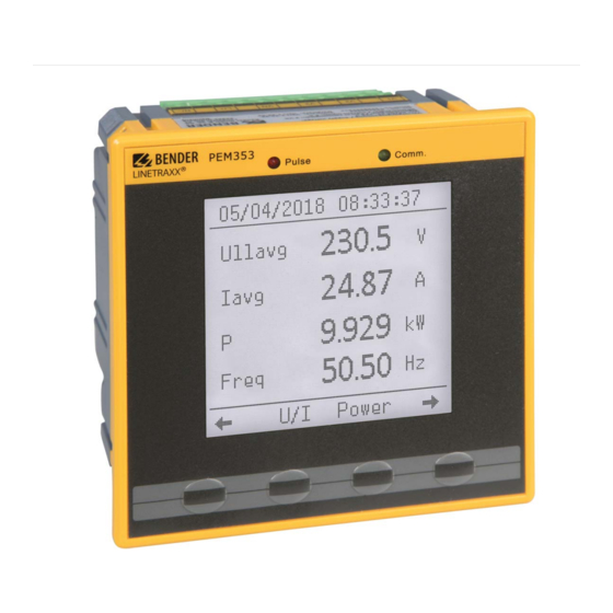
7. Operation 7.1 Getting to know the operating elements PEM353 Pulse Comm. Fig. 7.1: Operating elements Legend of the operating elements Element Description Pulse LED (red) Indication of energy pulsing Comm. LED (green) Indication of communication activity Display LCD graphic display Button 1 The function of the buttons varies depending on the context. -
Page 40: Led Indication
Operation 7.2 LED indication The universal measuring device features two LEDs on the front panel: "Pulse" (red) and "Comm." (green). 7.2.1 Pulse LED The "Pulse" LED is used when the EN PULSE function is activated. This can be set in the setup menu using the buttons on the front or via the communication interface (Setup >... -
Page 41: Standard Display
Operation 7.4 Standard display The standard display is the page to which the device returns from each menu after an adjustable time. The standard display shows the present measured values for 4 param- eters in plain text. These parameters can be freely selected (see page 56). If any button is pressed in the standard display, navigation to the non-changeable menus begins as described above (chapter 7.3). - Page 42 Tab. 7.1: Detail page "U/I" Notes Tab. 7.1 is the calculated current on the N conductor; r.m.s. value of (I for PEM353-N only „Fundamental“ (top line of the display): „Fundamental“ (top line of the display): value refers to the fundamental f...
-
Page 43: Detail Page "Power
Operation 7.5.2 Detail page "Power" Subpage First line Second line Third line Fourth line λ λ λ λ λ Displacement factor Displacement factor Displacement factor Displacement fac- tor cos (φ) cos (φ) cos (φ) cos (φ) Ltot L1 (f0) L2 (f0) L3 (f0) tot (f0) Tab. -
Page 44: Detail Page "Demand
Operation 7.5.4 Detail page "Demand" Subpage No. First line Second line Third line Peak demand P Peak demand Q Peak demand S Timestamp Timestamp Timestamp Peak demand P Peak demand Q Peak demand S Timestamp Timestamp Timestamp Max. Peak demand I Peak demand I Peak demand I Timestamp... -
Page 45: Detail Page "Harmonics
Operation 7.5.5 Detail page "Harmonics" Subpage No. First line Second line Third line 1 (THD 2 (THD 3 (TDD) k-factor I k-factor I k-factor I 4 (k-factor) Basic Crest factor I Crest factor I Crest factor I 5 (Crest factor) 6 (Unbalance) Unbalance I Unbalance U... - Page 46 Operation Subpage No. First line Second line Third line 1 (TOHD) TOHD3…15 for U and I 2 (TOHD) TOHD17…29 for U and I 3 (TOHD) TOHD31 for U and I (TEHD) TEHD2…14 for U and I (TEHD) TEHD16…28 for U and I (TEHD) TEHD30 for U and I 1 (TOHD)
-
Page 47: Detail Page "Max./Min
Operation 7.5.6 Detail page "Max./Min." Subpage No. First line Second line Third line Fourth line Ø U L1 max L2 max L3 max LN max Timestamp Timestamp Timestamp Timestamp Ø U L1 max L2 max L3 max LN max Timestamp Timestamp Timestamp Timestamp... - Page 48 Timestamp Timestamp Min. crest factor L1 Min. crest factor L2 Min. crest factor L3 Timestamp Timestamp Timestamp Min. current unbal- Min. voltage unbal- ance ance Timestamp Timestamp Tab. 7.6: Detail page "Max./Min. " Notes Tab. 7.6 for PEM353-N only PEM353_D00335_00_M_XXEN/06.2018...
-
Page 49: Detail Page "Tou
Operation 7.5.7 Detail page "TOU" (Time of Use) The Time of Use (TOU) has to be configured via the communication interface (see Mod- bus register from page 83). The events can be called up on the device. Subpage no. First line Second line Third line Active energy... - Page 50 Operation PEM353_D00335_00_M_XXEN/06.2018...
-
Page 51: Setup
8. Setup To enter the setup mode, scroll through the menu in the bottom line of the display using the arrow buttons until "Setup" appears. Activate the setup by pressing the "Setup" button. You can return to the display mode automatically after an adjustable time without pressing a button or immediately by manually pressing the "ESC"... - Page 52 Setup Setup Browse / Enter Password Wiring Mode, PT Primary, PT Secondary, CT Primary, CT Secondary, I4 Primary, I4 Secondary, Basic PF convention, kVA calculation, CT1...3 polarity, THD calculation method, Demand Period, No. of windows, Predicted response, EN pulse constant, LED EN pulse, EN Period, kvarh Calc., On Time Threshold Comm.
-
Page 53: Setup: Setting Options
CT Primary 1…30000 A (primary side) Select CT transformation ratio CT Secondary 1…5 A (secondary side) I4 Primary 1…30000 A For PEM353-N only I4 Secondary 1…5 A PF Convention IEC, IEEE, -IEEE IEC Power factor rule kVA Calc. Vector, scalar Vector... - Page 54 Setup Display entry Setting Factory Level 1 Parameter Description options settings Level 2 Total harmonic distortion (THDf ) THD Calc. THDf, THDr THDf or distortion factor (THDr) Set the measurement period for DMD Period 1…60 min 15 min demand measurement Set the number of No.
- Page 55 Setup Display entry Setting Factory Level 1 Parameter Description options settings Level 2 Setpoints Disabled Disabled Type Value exceeded Over Below value Under Parameter Monitored measured value OvLim Upper limit Group1…9 UnLim Lower limit see Tab. 13.1 ActiveDelay Active delay InactiveDelay Inactive delay Trigger 1 none...
- Page 56 Setup Display entry Setting Factory Level 1 Parameter Description options settings Level 2 Function Remote con- trol/Alarm kWh import Remote kWh export Set DO function control/ kWh total Alarm kvarh import kvarh export kvarh total Setpoints Disabled Disabled Type Value exceeded Over Below value Under...
- Page 57 Setup Display entry Setting Factory Level 1 Parameter Description options settings Level 2 Clock Time Set present time HH:MM:SS Date Set present date (20)YYMMDD YYMMDD Select date format for timestamp Date format MMDDYY YYMMDD and for the display DDMMYY Maintenance New Password Enter new password Password setup Confirm Pass-...
- Page 58 Setup Display entry Setting Factory Level 1 Parameter Description options settings Level 2 Clear all Data Clear all of the above data Yes/No Normal Normal DO Control Defines the state of the DO Normal Information Firmware Firmware version Update Date of last firmware update Modbus Modbus protocol version —...
- Page 59 Setup Reactive power import Quadrant 2 Quadrant 1 Power factor (+) Power factor (-) Active power export (-) Active power export (+) Reactive power import (+) Reactive power import (+) Active power import Quadrant 3 Quadrant 4 Power factor (-) Power factor (+) Active power export (-) Active power import (+)
- Page 60 Setup The response value can be 0.1…100 % of "I prim". I prim takes into account the connected external measuring current transformer: primary I prim = 5 A x secondary List of standard display options: , Ø U , Ø U , Ø...
-
Page 61: Inputs And Outputs
9. Inputs and outputs 9.1 Digital inputs (DI) The device provides four digital inputs which are internally operated with DC 24 V, have a sampling frequency of 1000 Hz and feature a programmable debounce time. The following functions can be used: Digital inputs are typically used for monitoring external states. -
Page 62: Digital Outputs (Do)
Inputs and outputs 9.2 Digital outputs (DO) The device features two digital outputs. These differ depending on the device: PEM353 Relay outputs PEM353-N Relay outputs PEM353-P Pulse outputs Digital outputs are generally used for alerting when a setpoint is triggered, for load control, for decoupling energy counting pulses or for remote-controlled applications. - Page 63 Pulse constant EN Pulse CNST:1000 or 3200 pulses kWh or kvarh PEM353-P Instead of the two relay outputs, the PEM353-P device variant has two solid-state pulse outputs which can be used for kWh and kvarh pulsing, among other things. Energy pulsing is typically used for accuracy tests.
- Page 64 Inputs and outputs PEM353_D00335_00_M_XXEN/06.2018...
-
Page 65: Power And Energy
10. Power and energy The following measured values are available: Parameter Σ Ø — — — λ — — — — — Energy meters Basic energy parameters include: Active energy (import*, export*, net energy and total energy in kWh) Reactive energy (import*, export*, net energy and total energy in kvarh) ... - Page 66 Power and energy PEM353_D00335_00_M_XXEN/06.2018...
-
Page 67: Demand Dmd
11. Demand DMD "Demands" are defined as average consumption values of the last concluded demand period. The length of the period can be determined (register 6029…6031, see page 115). In contrast, the "Predicted demands" are defined as average consumption values projected in real time for the present period, which is not yet concluded. - Page 68 Demand DMD Example 1 Duration of a sliding window = 1 minute Number of sliding windows for one demand value = 15 Result: A new demand value is provided once per minute as an average value over the last 15 minutes. Example 2 Duration of a sliding window = 15 minutes Number of sliding windows for one demand value = 1...
-
Page 69: Power Quality
12. Power Quality 12.1 Voltage and current phase angles Phase angle analysis is used to determine the angle between the voltages and currents of the three phase conductors. 12.2 Harmonic distortion The device provides an analysis of: All harmonics up to the 31 order ... -
Page 70: Thdf And Thdr
Power Quality 12.2.2 THDf and THDr THDf (Total harmonic distortion) and THDr (distortion factor) ∞ ∞ Σ Σ h = 2 h = 2 THDf x 100 % THDr x 100 % ∞ Σ h = 1 with h = harmonic order = r.m.s. -
Page 71: Measured Values Of The Harmonics
Power Quality 12.2.6 Measured values of the harmonics The following measured values are supported: L1 or L1L2 L2 or L2L3 L3 or L3L1 TEHD TEHD TEHD TOHD TOHD TOHD Harmonics voltage harmonic harmonic harmonic … … … harmonic harmonic harmonic TEHD TEHD TEHD... -
Page 72: Unbalance
Power Quality 12.3 Unbalance The device can measure voltage and current unbalances. The following calculation method is applied: Voltage unbalance = U2/U1 x 100 % Current unbalance = I2/I1 x 100 % with U1 = positive sequence component voltage U2 = negative sequence component voltage I1 = positive sequence component current I2 = negative sequence component current PEM353_D00335_00_M_XXEN/06.2018... -
Page 73: Setpoints
13. Setpoints The device features 9 user-programmable control setpoints which provide extensive control by allowing a user to initiate an action in response to a specific condition. Setpoints can be programmed via the communication interface or in the setup. Operation of the setpoints Setpoints only respond when the tripping limit value (…Lim) is violated for the defined minimum period (Active Delay). - Page 74 Setpoints "<" setpoints Parameter Inactive Inactive Delay Delay OvLim UnLim Active Delay Setpoint active inactive Fig. 13.2: Falling below the set value trips the setpoint The following setup parameters are available: 1. Setpoint type: defines the type of operation (over value = ">" setpoint, under value = "<"setpoint, deactivated).
- Page 75 100 % Voltage unbalance x 100 % Current unbalance x 100 % Phase reversal (PEM353-N only) Tab. 13.1: Setpoint parameters 3. Setpoint limit (OvLim) ">" setpoint: response threshold value "<" setpoint: release threshold value 4. Setpoint limit (UnLim) ">" setpoint: release threshold value "<"...
- Page 76 Setpoints ">" setpoint The measured value must exceed the setpoint limit (OvLim) in order to be activated (response threshold value) and fall below the setpoint limit (UnLim) in order to be deactivated (release threshold value). "<" setpoint The measured value must fall below the setpoint limit (UnLim) in order to be activated ...
-
Page 77: Log
FIFO principle (first in, first out): The present month overwrites the oldest stored month. 14.1 Max./Min. log The PEM353 stores each new maximum and minimum value of this month and last month. The stored values are listed in the table below. This month... - Page 78 This month Last month Maximum values Minimum values Maximum values Minimum values L3 max L3 min L3 max L3 min tot max tot min tot max tot min L1 max L1 min L1 max L1 min L2 max L2 min L2 max L2 min L3 max...
-
Page 79: Peak Demand Log
Time = (day x 100 + hour) where day = 1…28 and hour = 0…23. 14.2 Peak demand log The PEM353 stores the peak demand of the last month and of this month with times- tamp for I and S . -
Page 80: Monthly Energy Log
This month Last month Peak demand Q Peak demand Q Peak demand S Peak demand S Peak demand P (T1…8) Peak demand P (T1…8) Peak demand Q (T1…8) Peak demand Q (T1…8) Peak demand S (T1…8) Peak demand S (T1…8) Monthly self-read time (peak demand log) The self-read mechanism for the peak demand log is described by the content of register 6033. -
Page 81: Event Log (Soe Log)
Monthly self-read time (monthly energy log) The self-read mechanism for the monthly energy log is determined by the content of register 6034. 0: Data transfer takes place at 00:00 h of the first day of each month. Other numeric value: Data transfer takes place independently at a different time. ... - Page 82 PEM353_D00335_00_M_XXEN/06.2018...
-
Page 83: Time Of Use (Tou)
15. Time of Use (TOU) This function is used when electricity costs vary throughout the day and/or year (night, weekends, holidays, season…). Up to 8 different tariffs can be configured (only via the communication interface). The registers of the meter readings are described at chapter 16.2. The device provides 2 complete schedules between which can be switched at a prede- fined time or on command (write to register 7008: 0xFF00). - Page 84 Time of Use (TOU) The following diagram provides an overview of how the device chooses the tariff to be used: Start Control of the 8 tariffs via DI? Determine present time/date Determine present day type using the specified assignment (weekday <> day type) (Register 7009...7015) Schedule 2 Which schedule...
-
Page 85: Tariff Switch According To A Fixed Schedule
Time of Use (TOU) 15.1 Tariff switch according to a fixed schedule The following setup parameters are available: Setup parameter Definition Daily profile A daily profile defines the times during the day at which Start address 7200 (schedule 1) the system switches to a tariff that is also defined here. A Start address 8200 (schedule 2) total of 20 daily profiles can be defined for each schedule. -
Page 86: Tariff Switch By Changing The Status Of The Di
Time of Use (TOU) 15.2 Tariff switch by changing the status of the DI Up to 3 DI (DI1…3 only) can be used to select to which of the 8 possible tariffs the values should be added. Once DI1 is configured for the tariff switch, all automatic tariff schedules are ignored. -
Page 87: Modbus Register Map
This chapter provides a complete description of the Modbus register map for the PEM353 series to facilitate the access to information. In general, the registers are imple- mented as Modbus Read Only Registers (RO = read only) with the exception of the DO control registers, which are implemented as Write Only Registers (WO = write only). -
Page 88: Basic Measured Values
Modbus Register Map 16.1 Basic measured values Register Property Description Format Scale/unit 0000 Float 0002 Float 0004 Float Ø U 0006 Float 0008 Float L1L2 0010 Float L2L3 0012 Float L3L1 Ø U 0014 Float 0016 Float 0018 Float 0020 Float 0022 Ø... - Page 89 Modbus Register Map Register Property Description Format Scale/unit 0048 Float λ 0050 λ Float — 0052 Float λ λ 0054 Float 0056 Float Phase angle U or U (3P3W) 0058 Float L1L2 Phase angle U or U (3P3W) 0060 Float L2L3 Phase angle U or U...
- Page 90 Modbus Register Map Register Property Description Format Scale/unit 0112 Float L1(f0) 0114 Float L2(f0) 0116 Float L3(f0) 0118 Float tot (f0) 0120 Float 0122 UINT32 Pointer data recorder 1 0124 UINT32 Pointer data recorder 2 0126 UINT32 — Pointer data recorder 3 0128 UINT32 Pointer data recorder 4...
- Page 91 Tab. 16.2: Bit sequence status setpoints (0100) The diagnostic register 0101 shows wiring errors. In 3P4W and 3P3W mode, there is an error detection feature that detects voltage problems already during the PEM353 setup phase. The diagnosis is based on the following assumptions: - Voltage/current rotating field is equal - The measured active energy is assumed as the related active energy and is >...
- Page 92 Time during which the device has measured a higher current than the threshold value set in register 6049 on any phase on the secondary side (i.e. without CTs). for PEM353-N only When wiring mode "1P2W L-N" or "1P2W L-L" is selected, the registers are reserved.
-
Page 93: Energy Measurement
Modbus Register Map 16.2 Energy measurement After reaching the maximum value of 999,999,999 kWh/kvarh/kVAh, the measurement will roll over to 0 (overflow). 16.2.1 Energy meters and tariffs (present measured values) Register Register Register Register Energy Property Description Format Unit Σ L1…3 meters Active energy 0500... - Page 94 Modbus Register Map Register Register Register Register Energy Property Description Format Unit Σ L1…3 meters Active energy 0536 0656 0776 0896 INT32 import 0.1 x kWh Active energy 0538 0658 0778 0898 INT32 export Tariff 2 Reactive energy 0540 0660 0780 0900 INT32...
- Page 95 Modbus Register Map Register Register Register Register Energy Property Description Format Unit Σ L1…3 meters Active energy 0576 0696 0816 0936 INT32 import 0.1 x kWh Active energy 0578 0698 0818 0938 INT32 export Tariff 6 Reactive energy 0580 0700 0820 0940 INT32...
-
Page 96: Monthly Energy Log (Energy Log)
Modbus Register Map 16.2.2 Monthly energy log (Energy Log) Register Property Energy meters Description Format Value/unit 0980 INT16 0*…12 Month HiByte: year (0…99) 0981 INT16 LoByte: month (1…12) Timestamp HiByte: Day (1…31) (20YY/MM/DD 0982 INT16 LoByte: hour (0…23) hh:mm:ss) HiByte: minute (0…59) 0983 INT16 LoByte: second (1…59) - Page 97 Modbus Register Map Register Property Energy meters Description Format Value/unit 1030 Active energy import INT32 0.1 x kWh 1032 Active energy export INT32 1034 Tariff 3 Reactive energy import INT32 0.1 x kvarh 1036 Reactive energy export INT32 1038 Apparent energy INT32 0.1 x kVAh 1040...
-
Page 98: Interval Energy Measurement (En Period)
Modbus Register Map Notes Tab. 16.4: This register represents the month that has been read out. In addition to the present month, the last 12 months are available. Register content 0 = this month, 1 = last month, 2 = two months back, etc. -
Page 99: Power Quality
Modbus Register Map 16.3 Power Quality Register Property Description Format Unit 1300 Float 1302 Float 1304 Float TODD 1306 Float TODD 1308 Float TODD 1310 Float TEDD 1312 Float TEDD 1314 Float — TEDD 1316 Float k-factor I 1318 Float k-factor I 1320 Float... -
Page 100: Harmonics Currents
Modbus Register Map 16.4 Harmonics currents Register Property Description Format Unit 1400 Float 1402 Float 1404 Float TOHD 1406 Float TOHD 1408 Float TOHD 1410 Float TEHD 1412 Float TEHD 1414 Float — TEHD 1416 Float HD02 1418 Float HD02 1420 Float HD02... -
Page 101: Harmonics Voltages
Modbus Register Map 16.5 Harmonics voltages Register Property Description Format Unit or THD 1600 Float UL1L2 or THD 1602 Float UL2L3 or THD 1604 Float U31L1 TOHD or TOHD 1606 Float UL1L2 TOHD or TOHD 1608 Float UL2L3 TOHD or TOHD 1610 Float UL3L1... -
Page 102: Demand
Modbus Register Map 16.6 Demand Register Property Description Format Scale/unit Demand I 3000 Float Demand I 3002 Float Demand I 3004 Float Demand P 3006 Float Demand Q 3008 Float Demand S 3010 Float Tab. 16.10: Demands register 16.7 Predicted demand Register Property Description... -
Page 103: Peak Demand Of This Month
Modbus Register Map 16.8 Peak demand of this month Energy Register Property Description Format Unit meters Peak demand I of this month 3400…3405 Peak demand I of this month 3406…3411 Peak demand I of this month 3412…3417 Global 3418…3423 Peak demand P of this month 3424…3429 Peak demand Q of this month 3430…3435... -
Page 104: Peak Demand Of Last Month
Modbus Register Map Energy Register Property Description Format Unit meters 3562…3567 Peak demand P of this month See data struc- 3568…3573 Peak demand Q of this month ture Tab. 16.14 3574…3579 Peak demand S of this month Tab. 16.12: Register of peak demand this month 16.9 Peak demand of last month "Last month"... - Page 105 Modbus Register Map Energy Register Property Description Format Unit meters 3708…3713 Peak demand P of last month 3714…3719 Tariff 5 Peak demand Q of last month 3720…3725 Peak demand S of last month 3726…3731 Peak demand P of last month 3732…3737 Tariff 6 Peak demand Q of last month...
-
Page 106: Max./Min. Log
Modbus Register Map 16.10 Max./Min. log 16.10.1 Maximum values of this month Register Property Description Format Unit 4000…4005 L1 max 4006…4011 L2 max 4012…4017 L3 max Ø U 4018…4023 LN max 4024…4029 L1L2 max 4030…4035 L2L3 max 4036…4041 L3L1 max Ø... - Page 107 Modbus Register Map Register Property Description Format Unit λ 4144…4149 1 max λ 4150…4155 2 max — λ 4156…4161 3 max λ 4162…4167 tot max 4168…4173 (calculated) 4174…4179 n max or THD 4180…4185 UL1 max UL1L2 max or THD 4186…4191 UL2 max UL2L3 max or THD...
-
Page 108: Minimum Values Of This Month
Modbus Register Map 16.10.2 Minimum values of this month Register Property Description Format Unit 4300…4305 L1 min 4306…4311 L2 min 4312…4317 L3 min Ø U 4318…4323 LN min 4324…4329 L1L2 min 4330…4335 L2L3 min 4336…4341 L3L1 min Ø U 4342…4347 LL min 4348…4353 1 min... - Page 109 Modbus Register Map Register Property Description Format Unit λ 4444…4449 1 min λ 4450…4455 2 min — λ 4456…4461 3 min λ 4462…4467 tot min 4468…4473 (calculated) 4474…4479 n min or THD 4480…4485 UL1 min UL1L2 min or THD 4486…4491 UL2 min UL2L3 min or THD...
-
Page 110: Maximum Values Of Last Month
Modbus Register Map 16.10.3 Maximum values of last month Register Property Description Format Unit 4600…4605 L1 max 4606…4611 L2 max 4612…4617 L3 max Ø U 4618…4623 LN max 4624…4629 L1L2 max 4630…4635 L2L3 max 4636…4641 L3L1 max Ø U 4642…4647 LL max 4648…4653 1 max... - Page 111 Modbus Register Map Register Property Description Format Unit λ 4744…4749 1 max λ 4750…4755 2 max — λ 4756…4761 3 max λ 4762…4767 tot max 4768…4773 (calculated) 4774…4779 n max or THD 4780…4785 UL1 max UL1L2 max or THD 4786…4791 UL2 max UL2L3 max or THD...
-
Page 112: Minimum Values Of Last Month
Modbus Register Map 16.10.4 Minimum values of last month Register Property Description Format Unit 4900…4905 L1 min 4906…4911 L2 min 4912…4917 L3 min Ø U 4918…4923 LN min 4924…4929 L1L2 min 4930…4935 L2L3 min 4936…4941 L3L1 min Ø U 4942…4947 LL min 4948…4953 1 min... - Page 113 Modbus Register Map Register Property Description Format Unit λ 5050…5049 1 min λ 5050…5055 2 min — λ 5056…5061 3 min λ 5062…5067 tot min 5068…5073 (calculated) 5074…5079 n min or THD 5080…5085 UL1 min UL1L2 min or THD 5086…5091 UL2 min UL2L3 min or THD...
-
Page 114: Max./Min. Log Data Structure
Modbus Register Map 16.10.5 Max./Min. log data structure Offset Property Description Note HiWord: year 1…99 (year-2000) LoWord: month 1…12 HiWord: day 1…28/29/30/31 LoWord: hour 0…23 HiWord: minute 0…59 LoWord: second 0…59 + 4…+5 Max. or Min. value Tab. 16.19: Max./Min. log data structure 16.11 Setup parameters (basic) * = factory settings Register... - Page 115 Modbus Register Map Register Property Description Format Range/unit 0 = vector* 6022 Calculation method S UINT16 1 = scalar 0 = normal* 6023 Current transformer L1 polarity UINT16 1 = reversed 0 = normal * 6024 Current transformer L2 polarity UINT16 1= reversed 0 = normal *...
- Page 116 Modbus Register Map Register Property Description Format Range/unit Monthly freeze self-read time 6041 UINT16 (monthly log/freeze log) Daily freeze self-read time 6042 UINT16 (daily log/freeze log) Standard display (1 measured quan- 6043 UINT16 0…36, 7* tity) Standard display (2 measured quan- 6044 UINT16 0…36, 11*...
- Page 117 Modbus Register Map see register 9100 ff. 0: Data transfer takes place at 00:00 h of the first day of each month. 0xFFFF: Data transfer does not happen automatically at a specific time, but only by writing 0xFF00 to register 9603 (peak demand) or to register 9605 (Max./Min. log). By doing this, the data of the "Peak demand of this month"...
- Page 118 Modbus Register Map Key for measured values 1…4 on the standard display Parameter Parameter Key Parameter Key Parameter Import active tot (f0) energy, tar- iff 1 Import Total dis- active Ø I placement energy, tar- factor iff 2 Import active energy, tar- iff 3 Import...
-
Page 119: Setup (Inputs And Outputs)
Modbus Register Map Overview of the"DNP Polling Objects" Object description Setting options Object 1: Binary Inputs Object 10: Binary Output Object 20: 32-bit Binary Counters 0 = return 1 = enabled* Object 20: 16-bit Binary Counters Object 30: Analog Inputs Primary Readings Object 40: Analog Output Status Reserved 16.12 Setup (inputs and outputs) -
Page 120: Setup (Communication)
Modbus Register Map Register Property Description Format Unit 0* = remote control/setpoint 6230 DO1 function UINT16 1 = kWh import 2 = kWh export 3 = kWh total 4 = kvarh import 6231 DO2 function UINT16 5 = kvarh export 6 = kvarh total …... -
Page 121: Setup (Setpoints)
Modbus Register Map 16.14 Setup (setpoints) Register Property Description Format Unit 0 = disabled 6500 Setpoint type UINT16 1 = ">" setpoint 2 = "<" setpoint 6501 UINT16 0…32 Parameters 6502 Float Upper limit Setpoint 1 6504 Float Lower limit 6506 Active delay UINT16... - Page 122 Modbus Register Map Notes Tab. 16.23 1)Setpoint parameter key Parameter Parameter Parameter Present demand P TOHD — Present demand Q TEHD Present demand S Voltage unbalance Predicted demand Current unbalance Predicted demand Rotating field Predicted demand 26…29 Reserved TOHD TEHD λ...
-
Page 123: Tou Setup
Modbus Register Map 16.15 TOU setup Refer also to chapter 15. 16.15.1 Setup schedules register Register Property Description Format Range/Option Status register 7000 Currently active tariff UINT16 0…7 (T1…T8) 7001 Currently active season UINT16 0…11 (season 1…12) Currently active period of the 7002 UINT16 0…11 (period 1…12) -
Page 124: Season
Modbus Register Map Notes Tab. 16.24 If DI1 is configured for the tariff switch, the schedules are ignored and instead the status of the DI is used for the tariff switch. Register content 0xFFFFFFFF deactivates the automatic tariff switch. Data structure switching time: Byte 3 Byte 2 Byte 1... - Page 125 Modbus Register Map Offset Property Description Format Range/Option HiByte: month UINT16 Start date LoByte: day Weekday 1 daily profile UINT16 Season 4 Weekday 2 daily profile UINT16 0…19 Weekday 3 daily profile UINT16 HiByte: month UINT16 Start date LoByte: day Weekday 1 daily profile UINT16 Season 5...
- Page 126 Modbus Register Map Offset Property Description Format Range/Option HiByte: month UINT16 Start date LoByte: day Weekday 1 daily profile UINT16 Season 10 Weekday 2 daily profile UINT16 0…19 Weekday 3 daily profile UINT16 HiByte: month UINT16 Start date LoByte: day Weekday 1 daily profile UINT16 Season 11...
-
Page 127: Daily Profiles
Modbus Register Map 16.15.3 Daily profiles Daily profiles register (of schedules 1 and 2) Register Register Property Description Format schedule 1 schedule 2 7200…7223 8200…8223 Daily profile 1 7224…7247 8224…8247 Daily profile 2 7248…7271 8248…8271 Daily profile 3 7272…7295 8272…8295 Daily profile 4 7296…7319 8296…8319... - Page 128 Modbus Register Map Setup (daily profile data structure) Offset Property Period Format Value UINT16 0x0000 Start time Tariff to be used UINT16 0…7 (T1…T8) HiByte: hour (0…23) UINT16 Start time LoByte: minute (0…59) Tariff to be used UINT16 0…7 (T1…T8) HiByte: hour (0…23) UINT16 Start time...
-
Page 129: Alternate Days
Modbus Register Map Offset Property Period Format Value HiByte: hour (0…23) UINT16 Start time LoByte: minute (0…59) Tariff to be used UINT16 0…7 (T1…T8) Tab. 16.28: Daily profile data structure Notes Tab. 16.28: The start time for period 1 is 00:00 h and cannot be modified. Register content 0xFFFF terminates the settings of the daily profile. - Page 130 Modbus Register Map Offset Property Description Format Value Date UINT32 See data structure Tab. 16.30 Alternate day 88 Daily profile UINT16 0…19 Date UINT32 See data structure Tab. 16.30 Alternate day 89 Daily profile UINT16 0…19 Date UINT32 See data structure Tab. 16.30 Alternate day 90 Daily profile UINT16...
-
Page 131: Time Setting
Modbus Register Map 16.16 Time setting There are two time register formats supported by the PEM353: 1. Year/Month/Day/Hour/Minute/Second Register 9000…9002 2. UNIX time Register 9004 When sending the time via Modbus, care should be taken to only write one of the two time register sets. -
Page 132: Clearing Logs And Meters
Modbus Register Map 16.17 Clearing logs and meters Register Property Description Format Content 9600 Clear all concluded logs of the monthly energy UINT16 9601 UINT16 Clear all energy logs 9602 UINT16 Clear energy log of this month 9603 UINT16 Clear present peak demand (since last reset) 9604 UINT16 Clear all demand values... - Page 133 Operating hours counter: Time during which the device has measured more than 100 mA on any phase (secondary side, i.e. without considering the measuring current transformers). Executes the actions determined for registers 9600…9607 and 9610…9615. In addition, the PEM353-N clears the daily and monthly logs (freeze logs). For PEM353-N only Clearing the data recorders...
-
Page 134: Event Log (Soe Log)
Modbus Register Map 16.18 Event log (SOE log) Each event entry occupies 8 registers, as shown in the following table. The internal data structure of the event log is listed in Tabelle 16.34. Register Property Description Format 10000…10007 Event 1 10008…10015 Event 2 10016…10023... - Page 135 Modbus Register Map Offset Property Description HiByte: Reserved LoByte: Status +6…+7 Event value Tab. 16.34: Event data structure Event classification (SOE log) Event Event sub- Event classifica- classifica- Status Meaning value tion tion Digital input 1 closed/open Digital input 2 closed/open Digital input 3 closed/open (DI) Digital input 4 closed/open...
- Page 136 Modbus Register Map Event Event sub- Event classifica- classifica- Status Meaning value tion tion Status 1 = ">" setpoint U exceeded Trigger value Status 0 = return Status 1 = ">" setpoint U exceeded Trigger value Status 0 = return Trigger Status 1 = ">"...
- Page 137 Modbus Register Map Event Event sub- Event classifica- classifica- Status Meaning value tion tion Status 1 = ">" setpoint λ exceeded Trigger value Status 0 = return Status 1 = ">" setpoint demand P exceeded Trigger value Status 0 = return Status 1 = ">"...
- Page 138 Modbus Register Map Event Event sub- Event classifica- classifica- Status Meaning value tion tion Status 1 = ">" setpoint I exceeded Trigger value Status 0 = return 26…31 Reserved Status 1 = ">" setpoint I active Trigger value Status 0 = return Status 1 = ">"...
- Page 139 Modbus Register Map Event Event sub- Event classifica- classifica- Status Meaning value tion tion Status 1 = below "<" setpoint predicted demand P Trigger value Status 0 = return Status 1 = below "<" setpoint predicted demand Q Trigger value Status 0 = return Status 1 = below "<"...
- Page 140 Modbus Register Map Event Event sub- Event classifica- classifica- Status Meaning value tion tion System parameter fault Internal device fault (Diagnosis) Tariff schedule parameter fault Memory fault Supply voltage on Supply voltage off Present energy log cleared via front panel operation Stored energy log cleared via front panel operation Peak demand of this month cleared via front panel operation...
- Page 141 Clear all energy meters and tariffs (see footnote 1), peak demand and Max./Min. logs, device operating time, DI pulse counters For PEM353-N only: clear also data recorders, daily and monthly logs (freeze logs) Clear register for energy measurement (chapter 16.2) (except this month)
- Page 142 Modbus Register Map Clear monthly energy log of the present month (chapter 16.2.2, register content 0980 = 0) Clear all concluded energy logs of the last months (chapter 16.2.2, register content 0980 = 1…12) Tariff schedule has been switched with the following event values: Entry Description Manual switching from schedule 1 to schedule 2...
-
Page 143: Dox Control
(WO) and can be controlled with the function code 0x05 or 0x10. In order to query the current DO status, register 0098 has to be read out. When register 6032 = 1 is set, the PEM353 supports the execution of commands on the outputs in two steps (Arm Before Executing): Before sending an open or close command to one of the outputs, it must be "armed"... -
Page 144: Universal Measuring Device Information
Modbus Register Map 16.20 Universal measuring device information Register Property Description Format Note 9800… 9819 UINT16 Model 9820 Software version UINT16 E.g.: 10000 = V1.00.00 9821 Protocol version UINT16 E.g.: 40 = V4.0 Date of software update 9822 UINT16 (year-2000) Date of software update: 9823 UINT16... - Page 145 Modbus Register Map The universal measuring device model appears in registers 9800…9819. An encoding exam- ple is given in the table below using the "PEM353" by way of example. Register Value (Hex) ASCII 9800 0x50 9801 0x45 9802 0x4D 9803...
- Page 146 Modbus Register Map PEM353_D00335_00_M_XXEN/06.2018...
-
Page 147: Pem353-N
17. PEM353-N 17.1 Daily and monthly logs (freeze logs) Energy and demand values can be stored automatically at a specified time ("freeze logs"). Storage capacity daily log: 60 days (2 months) Storage capacity monthly log: 36 months (3 years) Both the setting of the log time and the log contents can only be accessed via the com- munication interface. - Page 148 PEM353-N Daily freeze log register Register Property Description Format Factor Unit 12000 INT16 1…60 Index HiByte: year-2000 12001 INT16 LoByte: month (1…12) HiByte: day (0…31) 12002 INT16 — LoByte: hour (1…23) HiByte: minute (0…59) 12003 INT16 LoByte: second (0…59) 12004...
-
Page 149: Monthly Freeze Log
PEM353-N 17.1.2 Monthly freeze log The following parameters are stored in the monthly log: Total active energy Total reactive energy Total apparent energy Peak demand P Peak demand Q Peak demand S ... - Page 150 PEM353-N To retrieve the values of a certain day from registers 12501…12527, a value N = 1…36 must be written to register 12000. The value N determines the month: 1 = previous month, 2 = two months back, etc. If an invalid value is written to the register (N = 0 or > 36), exception code 0x03 will be returned.
-
Page 151: Data Recorders Dr
PEM353-N 17.2 Data recorders DR There are 5 data recorders DR1…5 which can record up to 16 parameters each. Event in the event of a voltage interruption, the memory contents are not lost. Data recorders can only be programmed and read out via the communication interface. -
Page 152: Key To Measured Quantities Used For Data Recorders Dr
PEM353-N 17.2.2 Key to measured quantities used for data recorders DR 16 measured quantities per data recorder can be selected from the table below: Measured quantity (data recorder) Factor/unit Present measured value Ø U L1L2 L2L3 L3L1 Ø U Ø I λ... - Page 153 PEM353-N Measured quantity (data recorder) Factor/unit λ λ λ Phase angle U / phase angle U ° L1L2 Phase angle U / phase angle U ° L2L3 Phase angle U / phase angle U ° L3L1 Phase angle I °...
- Page 154 PEM353-N Measured quantity (data recorder) Factor/unit TEHD I TEHD I TEHD I k-factor I k-factor I k-factor I Crest factor I Crest factor I Crest factor I Unbalance U Unbalance I or THD L1L2 or THD L2L3 or THD L3L1...
- Page 155 PEM353-N Measured quantity (data recorder) Factor/unit HD31 or HD31 UL1L2 HD31 or HD31 UL2L3 HD31 or HD31 UL3L1 TOHD TOHD TOHD TEHD TEHD TEHD HD02 HD02 HD02 … HD31 HD31 HD31 Energy measurement DI1 pulse counter DI2 pulse counter DI3 pulse counter...
- Page 156 PEM353-N Measured quantity (data recorder) Factor/unit Net active energy Total active energy Reactive energy import varh Reactive energy export varh Net reactive energy varh Total reactive energy varh Apparent energy Reactive energy Q1 varh Reactive energy Q2 varh Reactive energy Q3...
- Page 157 PEM353-N Measured quantity (data recorder) Factor/unit Import reactive energy, tariff 4 varh Export reactive energy, tariff 4 varh Apparent energy, tariff 4 Import active energy, tariff 5 Export active energy, tariff 5 Import reactive energy, tariff 5 varh Export reactive energy, tariff 5...
-
Page 158: Factory Settings Data Recorders
PEM353-N Measured quantity (data recorder) Factor/unit Present demand Q Present demand S of the present demand period 1 max of the present demand period 2 max of the present demand period 3 max of the present demand period of the present demand period... - Page 159 PEM353-N Parameter Reactive Tariff 2: active Measured quantity 5 energy energy import import Reactive Tariff 2: active Measured quantity 6 energy energy export export Tariff 2: reactive Total reactive Measured quantity 7 energy energy import Tariff 2: reactive Net reactive Measured quantity 8 Ø...
-
Page 160: Reading Out The Data Recorders
PEM353-N 17.2.4 Reading out the data recorders Register Property Description Format 20000…20037 Log data recorder 1 20038…20075 Log data recorder 2 20076…20113 Log data recorder 3 see Tab. 17.8 20114…20151 Log data recorder 4 20152…20189 Log data recorder 5 Tab. 17.7: ata recorders register 17.2.5... -
Page 161: Technical Data
IC1 ............................AC 277 V / 480 V IC2 ................................... AC 300 V IC3 ................................AC/DC 250 V IC4, IC5 PEM353, PEM353-N ..........................AC 250 V PEM353-P..............................DC 30 V IC6 ..................................DC 30 V Rated insulation voltage IC1 / (IC2…7) ..............................500 V IC2 / (IC3…7) ..............................320 V... - Page 162 Technical data Rated impulse voltage IC1 / (IC2…7) ............................... 4 kV IC2 / (IC3…7) ............................... 4 kV IC3 / (IC4…7) ............................... 4 kV IC4 / (IC5…7) ............................... 4 kV IC5 / (IC6…7) ............................... 4 kV IC6 / IC7 ................................800 V Safe separation (reinforced insulation) between IC1 / (IC2…7) ......................overvoltage category III, 300 V IC2 / (IC3…7) ......................overvoltage category II, 300 V...
- Page 163 L1-N,L2-N,L3-N Current ..........................±0.2 % OMV, +0.05 % OFS 1, 2, 3 Neutral current (PEM353-N) ..........................±0.2 % OMV Frequency ................................... ±0.02 Hz Phasing ....................................±1 ° Active power, reactive power......................±0.5 % OMV, +0.05 % OFS Power factor λ ..................................±0.5 % Measurement of the active energy acc.
-
Page 164: Standards And Certifications
The specified standards take into account the edition valid until 11.2017 unless other- wise indicated. PEM353 was designed in accordance with the following standards: DIN EN 62053-22 (VDE 0418 Part 3-22) Electricity metering equipment (a.c.) - Particular requirements - Part 22: Static meters for active energy (classes 0.2 S and 0.5 S) (IEC 62053);... -
Page 165: Ordering Details
Technical data 18.3 Ordering details Type Article number PEM353-N 4 DI, 2 RO, RS-485 (Modbus RTU) Class 0.5 S for operation with 5 A measuring current transformers Class 1 S for operation with 1 A measuring current trans- formers B93100353... - Page 166 Technical data PEM353_D00335_00_M_XXEN/06.2018...
-
Page 167: Index
INDEX Demand DMD 67 Demand, duration measuring period 67 Detail page - "Demand" 44 - "Energy" 43 Apparent power, calculation 59 - "Harmonics" 45 Application example 20 - "I/O" 51 Areas of application 15 - "Max./Min." 47 - "Power" 43 - "SOE"... - Page 168 INDEX Front panel mounting 22 Navigation 40 Front view 21 Functional description 21 Functions 16 Operating elements 39 Operation 39 Harmonics 69 How to use this manual 9 Panel cutout 22 Phase angle - Current 69 Inputs, digital 34 - Voltage 69 Installation 21 Power and energy 65 Intended use 14...
- Page 169 INDEX Technical data 161 TEHD 69 Terminals 24 THD 45 THDf 70 THDr 70 TOHD 45 Total harmonic distortion 45 TOU 83 Training courses 11 Unbalance 72 Variants 19 Wiring diagrams 25 Work activities on electrical installations 13 Workshops 11 PEM353_D00335_00_M_XXEN/06.2018...
- Page 172 Bender GmbH & Co. KG Londorfer Str. 65 • 35305 Gruenberg • Germany Postfach 1161 • 35301 Gruenberg • Germany Tel.: +49 6401 807-0 • Fax: +49 6401 807-259 E-Mail: info@bender.de • www.bender.de © Bender GmbH & Co. KG All rights reserved.
Need help?
Do you have a question about the PEM353 and is the answer not in the manual?
Questions and answers