Table of Contents
Advertisement
Quick Links
Advertisement
Table of Contents

Summary of Contents for TATA Motors LP 613 EURO-II
- Page 1 Tata LP / LPT 613 EURO-II Operator’s Service Book (The contents given in this book are not binding; are subject to change without notice and are for illustration purposes only) Edition : XLI/NE/J-2007/001-500 International Business (CVBU) Mumbai, INDIA...
- Page 2 Dear Customer, We are pleased to hand over your Tata LP/LPT 613 EURO-II Vehicle, manufactured by Tata Motors where QUALITY is the watchword and major attention is paid even to minor details at all stages of manufacture of your vehicle.
-
Page 3: Table Of Contents
CONTENTS General About Tata LP/LPT 613 ..........3 EURO-II Environment protection ............5 Important tips for driver ............7 Tips for maintenance .............. 10 Body building ................11 Additional fitments ..............20 Additional provisions (electrical) ........30 Vehicle Handling Vehicle identification .............. 37 Location of aggregate numbers ......... -
Page 4: Table Of Contents
Driving Starting the engine ..............71 Driving ..................72 Stopping the engine ............... 75 Special operating conditions ..........76 Fuel economy ................78 Do it yourself ................79 Maintenance procedure Air intake system ..............83 Fuel system ................. 85 Lubrication system ..............87 Cooling system. -
Page 5: Table Of Contents
Technical information Technical specifications ............135 Aggregate filling capacities ..........140 Lubrication points ..............141 Tightening torques ..............143 Fuel, lubricants and coolants Fuel ....................149 Lubricants ................. 150 Coolant ..................152 Service recommendations Special instructions .............. 155 PDI ....................156 Service schedule .............. - Page 6 1. GENERAL About Tata LP/LPT 613 ......3 EURO-II Environment protection ........5 Important tips for driver ........7 Tips for maintenance ........10 Body building ............11 Additional fitments ........... 20 Additional provisions (electrical) ....30...
-
Page 7: About Tata Lp/Lpt 613 Euro-Ii
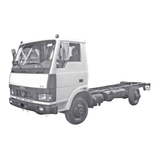
1.1 About TATA LP/LPT 613 EURO-II General TATA LP/LPT 613 EURO-II full reliability ease forward control chassis in truck & bus maintenance. versions are available with following Short wheel base and narrow width options : gives them high maneuverability, 3.8 meter wheel base for truck ideal for all applications. - Page 8 1.1 About TATA LP/LPT 613 General Steering is provided with steering lock cum ignition switch as a safety and security of the vehicle. Engine is started and stopped by means of this switch. Battery cut off switch in bus version provides additional safety for electrical system.
-
Page 9: Environmental Protection
1.2 Environmental protection General Environmental protection be kept running, avoid frequent revving up of engine. Also avoid TATA MOTORS is committed to frequent stopping produce vehicles using restarting, if uncalled for. environmentally sustainable It is not necessary to rev up the technologies. -
Page 10: Environment Protection
1.2 Environmental protection General Do not allow unauthorised This book contains further ● agencies to tamper engine information on driving precautions settings carry and maintenance care leading to modifications on the vehicle. environment protection. Please familiarise yourself with these Never allow the vehicle to run ●... -
Page 11: Important Tips For Driver
1.3 Important tips for driver General 1. Use only recommended oils and 11. Engine oil / coolant levels have lubricants. to be checked daily. Drain water from fuel water separator daily. 2. Always use recommended antifreeze agents in cooling 12. In case of air lock in fuel system, system to avoid deterioration of bleeding should be done on engine components due to... - Page 12 1.3 Important tips for driver General 19. Do not use clutch pedal as a foot 28. When air / fuel / oil filter rest when driving. This will cause cartridges are replaced, destroy premature clutch lining wear. old cartridges to prevent their reuse.
- Page 13 1.3 Important tips for driver General 39. Engagement / disengagement of power take off (optional fitment on trucks) needs to be done only when gear lever is in neutral position & engine running at idling speed. 40. Engine exhaust brake isolator switch has to be kept ON always, unless &...
-
Page 14: Tips For Maintenance
1.4 Tips for maintenance General 1. Use only recommended filters springs or axles for carrying for air intake, engine oil and fuel higher payload. It will result in system. Replace them at premature failure of aggregates recommended intervals. and deprive you of warranty benefits. -
Page 15: Body Building
1.5 Body building General Body building guidelines Position of roof luggage carrier (for LP model) It is important to ensure that the body is fitted to chassis in such a way that Roof luggage carrier should be placed the load imposed is transmitted to get the centre of gravity ahead of correctly. - Page 16 1.5 Body building General Notes Do not clamp bus body cross bearers to chassis cross Keep body weight minimum members. by selecting proper materials and designs. This will save fuel 10. No body mountings should foul and increase tyre life. with any chassis aggregate or frame cross member.
- Page 17 1.5 Body building General 18. No restriction should be placed 25. Do not use suspension spring beneath the remote mounted pack for earthing or to check air filter. Provide sufficient continuity while carrying out clearance for fitment and arc welding. Welding spatters removal of air cleaner.
- Page 18 1.5 Body building General CANVAS PACKING Section - AA Section - AA ‘U’ Bolt ‘U’ Bolt fastening with fastening with wooden runner steel runner 1. Hex. nuts M 16 x 1.5, -8.8 quality 2. Plate washer 3. Wooden runner 4. Steel runner 5.
- Page 19 1.5 Body building General Polyamide (PA) nylon tubing for Check that PA tubes is not ● air brake rubbing against any other object on the vehicle such as frame, Your vehicle is fitted with latest bracket or connectors. generation polyamide (PA) nylon tubing for air brake.
- Page 20 1.5 Body building General Guidelines and precautions for nylon (PA) tubing. Welding and gas cutting Cover PA tube with suitable object such as metal sheet at the time of welding and gas cutting. This will avoid welding spatter and molten metal from falling on the PA tubes Unprotected areas while welding and creating a hole in the PA tube.
- Page 21 1.5 Body building General Hot objects Take care that PA tubes do not touch hot objects such as exhaust pipe. This will avoid burning or melting of PA tube. Avoid PA tube to touch exhaust pipe Do not light fire near PA tube Clamp PA tubes properly to avoid coming in contact with hot objects Sharp objects Take care that PA tubes do not come in contact with sharp objects.
- Page 22 1.5 Body building General Loose fitments Do not allow loose fitting of PA tube. Avoid loose fitting of PA tube Ensure proper clamping of PA tubes Misuse Do not step or hang on connected PA tube. Doing so, will lead to damage of PA tube at the clamps or near end fitting, resulting in leakage.
- Page 23 1.5 Body building General Tube Fitment In case refitting of PA tube is required Follow original routing of PA tube. Take care that PA tubes are not forcibly bent or fitted. Use plastic coated clamps. Do not tighten nut without holding PA tube Use both hands while fitting PA tube.
-
Page 24: Additional Fitments
1.6 Additional fitments General A) Rear under run protection device (RUPD) This device is factory fitted on truck version. Rear under run protection device fitted on vehicle (LPT) Side under run protection device (SUPD) LOAD BODY BOTTOM OF FLOOR OVER ALL LENGTH Fitment of SUPD on LPT version Note : While the SUPD is fitted as OE on vehicles with OE load body, customers have to ensure fitment of SUPD when they do body building. - Page 25 Dimn ‘H’ is as measured on to be done for rust load bodies prevention. manufactured by other than Tata Motors supplied All the members as shown load body. in drg. are with minimum cross sections and thickness As per the regulations, required.
- Page 26 1.6 Additional fitments General SUPD Proposal 1 STEEL CROSS RUNNER 2 WELD NUTS ITEM NO. 4 HEX. FLANGED SCREW M10x20-IS 17130-8.8 ITEM NO. 2 & 3 THIS SURFACE SHOULD BE ITEM NO. 5 INSIDE THE MAX. WIDTH OF ITEM NO. 1 VEHICLE AND SHOULD NOT BE MORE THAN 120 mm INSIDE.
- Page 27 1.6 Additional fitments General ITEM NO. 1 ITEM NO. 2 AND 3 (RH & LH) R3 (TYP) 5 (TYP) R1.5 DETAILS -`X' R4.5 34.5 SECTION - AA MATERIAL - SHT 1.6 THK. D513 SS: 4010 MATERIAL - SHT 1.6 THK. D513 SS: 4010 ITEM NO.
- Page 28 1.6 Additional fitments General ITEM NO. 6 ITEM NO. 7 ITEM NO. 7 ITEM (OVERALL LENGTH -12) NO. 8 PITCH OVERALL LENGTH MATERIAL - SHT. 1 THK. D513 SS:4010 ITEM NO. 8 ITEM NO. 9 WELD NUT M10 -IS: 8856 33.5 2 HOLES 12.5 DIA-H11 (TYP)
- Page 29 1.6 Additional fitments General SUPD ALTERNATE PROPOSAL - 2 : a) with mounting to wooden runner b) Two alternate sections for panel (item no. 3) WOODEN RUNNER FRONT OF VEHICLE WOODEN RUNNER BOTTOM OF SIDE WALL OF LOAD BODY ITEM NO .-1 ITEM NO .-2 ITEM NO .-4...
- Page 30 1.6 Additional fitments General HEX. BOLT M10x100 BRT. WASHER 10.5 SPRING WASHER B10 WOODEN CROSS HEX. NUT M10 MEMBER 4x30x30 SECTION - FF HEX. SCREW M8x20 BRT. WASHER 8.4 SPRING WASHER B8 HEX. NUT M8 ITEM NO. 3b ITEM NO. 3a SECTION - CC SECTION - CC PROPOSAL - A...
- Page 31 1.6 Additional fitments General ITEM NO. 3a - PROPOSAL - A LENGTH OF SIDE PANEL MATERIAL - RECTANGULAR TUBE 100x25x1.5 THK (MINIMUM) HF YST 210 IS : 4923 ITEM NO. 3b - PROPOSAL - B (TYP) MATERIAL - SHEET 1 THK. D 513 SS : 4010 ITEM NO.
- Page 32 1.6 Additional fitments General C) Rear view mirror - LP / LPT versions BUS BODY TRUCK CAB 2 1 0 (Z=20) BUS BODY TRUCK BODY 16.5 DETAILS OF `A' 1008 ASSY. REAR VIEW MIRROR R.H. DETAILS OF `B' Note : Rear view mirror will be supplied as a kit with cowl and faceless chassis and should be fitted during body building.
- Page 33 1.6 Additional fitments General Rear view mirror - LP / LPT versions Mirror for custom built cab For LCVs there will be two plain mirrors one each at driver side and co-driver side. SL. CSK SCREW M6x20 - 4.8 RUBBER PAD TOP WASHER C 6.4 SPR.
-
Page 34: Additional Provisions (Electrical)
1.7 Additional provisions (electrical) General D) WIPING SYSTEM rubber edge of blade against the wind screen. GUIDELINES FOR FITMENT OF WIPER SYSTEM BY BODY BUILDERS Wiper system should be balanced and it is to be Wiper system components ensured that there is no (wiper motor, wheel box, possibility of entangling / wiper arm and blade, linkages) - Page 35 1.7 Additional provisions (electrical) General LIGHTING AND SIGNALLING lamps and side retro reflectors. These are to be fitted on all vehicles of Guidelines for fitment of end overall length more than 6 meters. outline marker lamp, side marker The distance restrictions are given in lamp, side retro-reflector, side the figure.
- Page 36 1.7 Additional provisions (electrical) General...
- Page 37 1.7 Additional provisions (electrical) General...
-
Page 38: Vehicle Identification
Know Your Vehicle Vehicle identification ........... 37 Location of aggregate numbers ....... 41 Instrument panel ............43 Switches, gauges & indicators ........44 Driving controls .............. 55 Turbocharger ..............57 Charge air cooler ............58 Clutch booster ..............59 Cab tilting ................. 60 2.10 Heating ................ - Page 39 2.1 Vehicle identification Know Your Vehicle LPT 613 - Full forward control truck with tilt cab (RHS view) LPT 613 - Full forward control truck with tilt cab (LHS view)
- Page 40 2.1 Vehicle identification Know Your Vehicle CHASSIS TYPE DESIGNATION Description Wheel Chassis Sales base type designation LPT VERSIONS FULL FORWARD CONTROL CHASSIS WITH 3800mm 381 325 LPT 613/38 CAB AND WITHOUT LOAD BODY, TRUCK VERSION WITH 697TCIC BHARAT STAGE-II ENGINE, WITH FULL AIR S’CAM BRAKE WITH HEATING AND DEMISTING, 3800mm W.B.
- Page 41 2.1 Vehicle identification Know Your Vehicle...
- Page 42 2.1 Vehicle identification Know Your Vehicle...
-
Page 43: Location Of Aggregate Numbers
2.2 Location of aggregate numbers Know Your Vehicle 1. Chassis number plate Engine number plate location 2. Cab /Cowl number plate Engine number plate Chassis number - LHD Cab / Cowl number plate Chassis number plate... - Page 44 2.2 Location of aggregate numbers Know Your Vehicle Power steering gearbox number plate Front axle number plate Gearbox number Rear axle number plate...
-
Page 45: Instrument Panel
2.3 Instrument panel Know Your Vehicle 19 20 21 22 23 24 25 26 Instrument panel Low air pressure indicator 14. Rear fog lamp indicator High beam indicator 15. Air filter service indicator Exhaust brake indicator 16. Glow plug indicator Parking brake indicator 17. -
Page 46: Switches, Gauges & Indicators
2.4 Switches, gauges & indicators Know Your Vehicle Fuel gauge Fuel gauge indicates the level of fuel in tank. It is electrically operated. Fuel level is indicated on gauge through a sensing unit mounted on fuel tank. Coolant temperature gauge Temperature gauge indicates coolant temperature. - Page 47 2.4 Switches, gauges & indicators Know Your Vehicle SERV indicator When it glows, it indicates that the Air cleaner filter is choked. Filter needs to be cleaned/ replaced. When the ignition key is in ON position, before starting the engine this indicator should glow SERV indicator GLOW indicator...
- Page 48 2.4 Switches, gauges & indicators Know Your Vehicle High beam indicator When it glows, it indicates that the head lights high beams are on. It is provided in speedometer dial. High beam indicator Parking brake indicator This indicator comes ON when parking brake is applied and goes OFF when it is released.
- Page 49 2.4 Switches, gauges & indicators Know Your Vehicle Exhaust brake indicator This indicator comes ON when exhaust brake is in operation Hazard warning indicator Exhaust brake indicator It comes 'ON' when hazard warning lights are switched 'ON' to warn the other road users about the hazardous condition of vehicle.
- Page 50 2.4 Switches, gauges & indicators Know Your Vehicle Seat belt indicator It comes ‘ON’ when seat belt is not fasten or belt tongue is not locked in to buckle. Seat belt indicator Exhaust brake isolator switch Exhaust brake can be made inoperative, by exhaust brake isolator switch, whenever required.
- Page 51 2.4 Switches, gauges & indicators Know Your Vehicle Rear fog lamp switch: This switch is provided to switch on Rear fog lamps. Rear fog lamps are operative only when the park lamps along with Head lamps (Hi beam/ Low beam) or Front fog lamps are switched ON.
- Page 52 2.4 Switches, gauges & indicators Know Your Vehicle Battery cut off switch Bus chassis is provided with battery cut off switch to isolate battery from electrical system when required. Battery is connected to starter motor and other circuits through isolator switch.
- Page 53 2.4 Switches, gauges & indicators Know Your Vehicle Steering lock cum ignition switch It is located on right hand side of steering column. It has following positions. ‘LOCK’ Position Key can be inserted or removed in this position only. Steering wheel gets locked, only when key is removed.
- Page 54 2.4 Switches, gauges & indicators Know Your Vehicle POSITION FOR FLASH (HIGH BEAM) POSITION FOR WASH-ON POSITION FOR LOW BEAM POSITION FOR HIGH BEAM HAZARD WARNING SWITCH POSITION FOR LEFT POSITION FOR RIGHT Combination switch Combination switch Combi switch is mounted on steering column.
- Page 55 2.4 Switches, gauges & indicators Know Your Vehicle Lights Lights are operated by turning the knob of this lever as indicated below OFF POSITION First notch (PL position) Parking lights, instrument panel lights, number plate lights, control 'PL' POSITION backlights and top marker lights are switched ‘ON’...
- Page 56 2.4 Switches, gauges & indicators Know Your Vehicle Windshield wiper and washer POSITION FOR WASH-ON The lever on other side is for operating windshield wiper and washer. This lever is located on LH side on RHD vehicle and RH side in LHD vehicle.
-
Page 57: Driving Controls
2.5 Driving controls Know Your Vehicle Driving controls LHD 1. Accelerator pedal 6. Steering wheel 2. Brake pedal 7. Combiswitch lever (Lights) 3. Clutch pedal 8. Instrument panel 4. Parking brake 9. Steering lock cum ignition switch 5. Gear shift lever 10. - Page 58 2.5 Driving controls Know Your Vehicle KSB unit (for Euro II vehicles) KSB unit is a cold start throttle advance mechanism. It is an integral part of fuel injection pump. KSB unit Provides necessary advance in lower throttle operation during cold condition.
-
Page 59: Turbocharger
2.6 Turbocharger Know Your Vehicle Turbocharger (Euro II) engine because malfunctioning of turbocharger, take Lubrication of the turbocharger your vehicle to Tata authorised workshop. Rotor assembly of turbocharger is Following precautionary measures supported by two floating lead should be taken to obtain trouble bronze sleeve bearings in the free performance. -
Page 60: Charge Air Cooler
2.7 Charge air cooler Know Your Vehicle Charge air cooler (Euro II) TURBOCHARGER EXHAUST INLET Charge air cooler Advantages of charge air cooler Hot air coming out of turbo charger flows through charge air cooler and gets cooled before entering intake manifold, thus increasing density of intake air for better combustion. -
Page 61: Clutch Booster
2.8 Clutch booster Know Your Vehicle Port 1. Inlet port (for compressed air) Port 3. Vent (for compressed air) Port 4. Control port (for clutch fluid) 2. Piston 3. Piston 4. Piston 5. Push rod 6. Return spring 7. Wind pipe 8. -
Page 62: Cab Tilting
2.9 Cab tilting Know Your Vehicle RELEASED POSITION BEFORE TILTING Cab tilting and locking lever arrangement RELEASED AND TILTED POSITION Cam lever handle Cab mounting mechanism Cam lever Mounting pin Primary locking lever handle 10. Mounting hook Primary locking lever 11. - Page 63 2.9 Cab tilting Know Your Vehicle Cab Tilting Truck version of 613 vehicle is provided with tilt cab. For tilting the cab proceed as follows : To raise the cab 1. Park vehicle on level ground in straight ahead condition and apply parking brake.
- Page 64 2.9 Cab tilting Know Your Vehicle 3. Hold primary locking lever ad pull cam lever handle to release primary locking lever from locked condition. (sketch position No. (4)) 4. Raise primary locking lever handle to horizontal positions. Mounting pins of cab mounting mechanism get released from mounting hooks.
- Page 65 2.9 Cab tilting Know Your Vehicle To lower the cab 1. Holding cab, press cab stay releasing lever and slightly lower cab. Linkage gets released from straight position. (sketch position No. (7)) 2. Lower cab till cab gets seated on rubber pads.
- Page 66 2.9 Cab tilting Know Your Vehicle 4. After locking, make sure that the cab is fully secured with the mounting hooks. (sketch position No. (10)) 5. Fit back padlock or bolt and nut on primary locking lever. (sketch position No. (11) & (12))
-
Page 67: Heating
2.10 Heating Know Your Vehicle Slot A Slot B Slot C Slot C Heating control Slot - 'B' Air Distribution Control Heating control (Optional) Air directed towards chest Heating system is provided for and legs comfortable driving. Heating system can be operated as per need. Air directed towards legs, The cab heat can be regulated by chest and windscreen... -
Page 68: Driver Seat & Seat Belt
2.11 Driver seat & seat belt Know Your Vehicle Driver seat adjustment Lever 1 : Lever for adjusting back rest. Lever 2 : Lever for adjusting seat height at rear. Lever 3 : Lever for horizontal movement of seat. Lever 4 : Lever for adjusting seat height at front. - Page 69 2.11 Driver seat & seat belt Know Your Vehicle Seat belt arrangement 1. Anchor 2. Webbing 3. Tongue 4. Buckle 5. Release button Seat belt Precautions : On truck versions three point belt for The belt is designed for use of ●...
-
Page 70: Starting The Engine
3. Driving Starting the engine, ............71 Driving ................... 72 Stopping the engine ............75 Special operating conditions ........76 Fuel economy ..............78 Do it yourself ............... 79... -
Page 71: Driving
3.1 Starting the engine Driving 1. Ensure that parking brake is applied. 2. Move gear shift lever to neutral position. 3. Insert ignition key in steering lock cum ignition switch. Steering wheel will be in locked condition. Turn the key to “ACC” position. - Page 72 3.2 Driving Driving Engaging position for various gears are shown on gear knob. Change gears at appropriate speed and do not lug the engine by too early high gear changes at low speed. 1 3 5 Reverse gear should only be engaged when vehicle has been brought to a complete stop.
- Page 73 3.2 Driving Driving We, therefore, recommended to effect. Do not ride brakes. This drive in fifth gear at a steady speed will lead to over heating of brake of about 70 kmph. Optimum fuel drums and linings resulting in consumption is achieved at this low brake efficiency.
- Page 74 3.2 Driving Driving Since exhaust opening is restricted, road wheels will drive engine, which will act as a compressor (resistor), thus retarding vehicle speed. Use of engine exhaust brake results in increased life of brake linings, brake drums & tyres. Isolator switch (Exhaust brake) In certain situations like starting of Hand brake valve...
-
Page 75: Stopping The Engine
3.3 Stopping the engine Driving Operating instructions shut off valve and fuel supply is cut off. Engine will stop. This shut 1. Ensure air pressure in the system off timer is aborted in case you is above 5 bar. turn ignition key again to ON 2. -
Page 76: Special Operating Conditions
3.4 Special operating conditions Driving Flame start system (BERU): Flame start system is provided for convenient starting at cold conditions by heating the intake air by means of burning the diesel in air intake manifold. Pre-glow time of just 20~45 ●... - Page 77 3.4 Special operating conditions Driving hot heater rod of the flame glow plug, evaporates and ignites. The post heating operation begins once the start procedure has ended. The duration is determined by the engine temperature (coolant water) when the post heating commences. Power continues to be supplied to the flame glow plugs, the solenoid valve remain open and indicator light...
-
Page 78: Fuel Economy
3.5 Fuel economy Driving Fuel Economy descending. Make maximum use of exhaust brake while descending. Drive smoothly, accelerate With a little pressing of brake pedal, gradually, avoid harsh exhaust brake first comes into action. acceleration. This will relieve driver of fatigue and Best fuel consumption is will increase the life of tyres, brake obtained at low engine speeds... -
Page 79: Air Intake System
4. Maintenance Procedure Air intake system ............83 Fuel system ..............85 Lubrication system ............87 Cooling system............... 89 Clutch ................92 Gearbox ................94 Propeller shaft ..............95 Front axle & rear axle ............ 96 Power steering ............... 97 4.10 Brake system .............. - Page 80 4.1 Air intake system Maintenance Slit for dust Atmospheric air separation Primary from intake duct Electric service cartridge indicator Air to turbo charger Plastic cover Dust bowl Cyclonic pre-cleaner Secondary cartridge Schematic details of dry type air filter Maintenance of dry type air filter Replacement of air filter primary cartridge (Vehicle with Euro II engine)
- Page 81 4.1 Air intake system Maintenance Charge air cooler (CAC) (with Euro II engine) Inspection If engine experiences a turbocharger failure or any other occasion where oil or debris has entered into CAC, the CAC must be cleaned. Remove CAC from vehicle. Charge air cooler Visually inspect CAC for cracks, holes and damage.
-
Page 82: Fuel System
4.2 Fuel system Maintenance Fuel water separator cum primer:- It is fitted in between fuel tank and FIP. It separates water particles in fuel. Fuel passes over funnel like cone in water separator and water being heavier than fuel, so water gets collected at the bottom of the bowl. - Page 83 4.2 Fuel system Maintenance If performance of engine is affected due to presence of air in fuel system (commonly known as air lock), it can be rectified by bleeding fuel system. Fuel system bleeding 1. Ensure no leakage in fuel line. 2.
-
Page 84: Lubrication System
4.3 Lubrication system Maintenance Changing engine oil / oil filter Engine oil should be drained while it is still hot. Unscrew sump drain plug and allow oil to drain out for 20 minutes. Unscrew drain plug of oil filter, drain out oil and refit drain plug. Unscrew centre bolt and Full flow engine oil filter assembly remove oil filter bowl, clean... - Page 85 4.3 Lubrication system Maintenance Clean the drain plug of oil sump and refit with a new sealing washer, if necessary. Tighten drain plug to 4 to 6 mkg torque. Fill in recommended quantity of engine oil in sump. Start engine and allow it to run for a few minutes and stop the engine.
-
Page 86: Cooling System
4.4 Cooling system Maintenance Cooling system A transparent radiator auxiliary tank is fitted between cabin rear wall and load body on LPT 613 vehicles. On LP 613 this is fitted behind driver seat. Maximum & minimum levels indicated on the body. It is fitted with two identical caps with pressure cum vacuum relief valve having 0.5 bar pressure setting. - Page 87 4.4 Cooling system Maintenance Always use genuine auxiliary tank Again operate the engine for 5 mins. cap. A proper cap firmly fitted with water temperature above 80 maintains pressure in the cooling at maximum engine speed. system and makes engine more Stop engine and drain water.
- Page 88 4.4 Cooling system Maintenance Fan belt tension adjustment 1. Loosen idler pulley flange nuts 1, 2 and the tensioner rod mounting nut 3 as shown in the picture, to release the fan idler pulley arrangement. 2. Loosen the check nut A and rotate adjusting nut B to get the desired tension of fan belt.
-
Page 89: Clutch
4.5 Clutch Maintenance Clutch pedal adjustment A=126mm M a s t e r cylinder Hydraulically operated clutch has been fitted on this vehicle. Clutch pedal height adjustment is required only in case of component Check nut repairs/overhaul etc. Adjustment is Stopper screw Clutch pedal not required during normal... - Page 90 4.5 Clutch Maintenance Clutch fluid filling and bleeding Procedure for bleeding the system given below : Remove filler cap and fill the clutch fluid container with fresh brake fluid. Remove dust cap from slave cylinder bleed screw and clean it thoroughly. Attach bleed tube to the bleed screw and place Filling clutch fluid other end of the tube in a clean...
-
Page 91: Gearbox
4.6 Gearbox Maintenance Gear box oil checking Check level of gear box oil. Top up if necessary. Gear box oil change Drain while hot. Fill the gear box with new oil. Capacity : 5.2 Litres 5.8 Litres Recommended oil Grade SYN gear EP 75 W 90 GL 4 Gulf Gear box (GBS - 40) grade. -
Page 92: Propeller Shaft
4.7 Propeller shaft Maintenance Propeller shaft Propeller shaft, U-joint cross bearing and sliding yoke should be regularly greased. Failure to do so may result in rapid wear and tear of the bearings and centre bearing mountings. Periodically check and if necessary, tighten mountings of centre bearing bracket to 8 mkg torque. -
Page 93: Front Axle & Rear Axle
4.8 Front axle & rear axle Maintenance Hub grease for front & rear hubs to be changed at every 36000 kms. Hub greasing and adjustment Remove front and rear wheel hubs. Dismantle and clean bearing and other components. Re-pack with bearing grease. -
Page 94: Power Steering
4.9 Power steering Maintenance Then turn steering wheel several times from lock to lock so that air escapes from the system. Keep watching oil level. Add oil immediately when oil level drops. Keep adding oil till the level remains at upper mark on dipstick and air bubbles are no longer visible in oil tank when steering wheel is turned. - Page 95 4.9 Power steering Maintenance Oil level check-up with the engine running With engine running, oil level will drop slightly, since oil requires a pressure of appox. 2-4 bar to overcome flow resistance when flowing through the system. Add enough oil to keep oil at upper mark. Stop engine.
- Page 96 4.9 Power steering Maintenance Power steering pump belt tension adjustment Checking and adjustment of steering pump belt tension. a. Loosen bolt holding upper mounting of steering pump to the clamping piece. b. Loosen steering pump pivot pin nut. c. Loosen the locknut & adjust belt tension by rotating the adjusting nut.
- Page 97 4.9 Power steering Maintenance Sector shaft play adjustment If play is noticed on drop arm or input shaft of steering gear box, it is to be adjusted as given below : Bring steering wheel to SAP ● (Straight Ahead Position). Sealing nut is to be loosened in ●...
-
Page 98: Brake System
4.10 Brake system Maintenance S Cam full air brakes air pressure, thus releasing parking brake. For parking / emergency S cam brakes are fully air operated braking, hand brake valve is operated brakes. Brake actuators at front and for depleting air to atmosphere, thus rear axles are externally mounted applying parking brakes. - Page 99 4.10 Brake system Maintenance...
- Page 100 4.10 Brake system Maintenance...
- Page 101 4.10 Brake system Maintenance All normal setting should be made only by means of adjuster screw to slack adjuster. Brake adjustment is to be done when drums are cold and not when they are hot. Improper brake adjustments can cause brake grabbing, more air consumption or POSITION AT ZERO STROKE...
-
Page 102: Springs
4.10 Brake system Maintenance Hand brake (parking brake) Hand brake is integral with spring brake actuator on rear axle. Spring brake chamber piston ram acts directly on push rod assembly of brake chamber. Parking brake adjustment No separate adjustment is required. Service brake adjustment holds good Hand brake valve for hand brake also. - Page 103 4.10 Brake system Maintenance 2. Loosen check nut on pedal FIRE WALL stopper screw located near stop light switch. Adjust stopper screw such that brake pedal free play travel is between 3 to 6 mm. 3. Tighten check nut of stopper screw without disturbing stopper screw.
- Page 104 4.10 Brake system Maintenance Load conscious pressure reducing valve (If ABS is not fitted) This valve is located in rear brake circuit and regulates supply of pressurised air to rear brake chambers depending on the load on rear axle. This enables rear brake actuation proportional to the load on rear axle and avoids wheel locking in partially loaded conditions.
- Page 105 4.10 Brake system Maintenance Anti Lock Brake System (ABS) the system turns off automatically (if fitted) indicated by a ‘(ABS)’ warning indicator on the dash board, still the ABS combined with the traditional ordinary brake system continues to hydraulic brake system prevents the work.
- Page 106 4.10 Brake system Maintenance Safety tips while driving with ABS requires a little longer stopping distance than a vehicle with conventional During a hard braking or when brake system on a loose or the road grip is poor, you will uneven surface, such as gravel feel an audible noise in the or snow.
- Page 107 4.10 Brake system Maintenance Brake system routine checks The low air pressure indicator should be off at the specified 1. Routine checks - I value (5.4 0.5 bar). If not, rectify. It is very essential that brake g. Continue to charge the system system is kept trim at all times till ‘cut-out’...
- Page 108 4.10 Brake system Maintenance Jack up the rear axle. Rotate 2.1 System protection valve wheels manually. Apply hand (SPV) brake. It will not be possible to A. Opening pressures rotate wheels. Hand brake Fail one service circuit say rear indicator appears on panel. circuit (port 21) by opening any Release hand brake.
- Page 109 4.10 Brake system Maintenance For checking closing pressure of 2.3 Brake chambers port 23, 24 pressure gauges With brakes applied at full should be connected in their pressure, check for leakages in circuits. Leak out air in either front and rear brake chambers. front (22) or rear tanks (21).
- Page 110 4.10 Brake system Maintenance FRIENDLY SERVICE TIPS 6. Any extra air connection to auxiliaries like air horn should be 1. Braking performance will drop taken from exhaust brake circuit down after brake chamber push only and not from parking brake rod travel of 45 mm in brakes circuit or service brake circuits.
- Page 111 4.11 Springs Maintenance Springs U-bolt nuts and check nuts of front/ rear springs should be regularly tightened with a torque wrench or with a socket wrench and a handle of atleast 60 cm length. Specified torques are given below : ‘U’...
-
Page 112: Centre Flap
4.12 Centre flap Maintenance Cable adjustment on centre flap locking mechanism. Centre flap is locked by two ● piece toggle locks fixed on front end of fire wall on LH & RH sides. Centre flap gets locked when it ● is lowered and pressed gently against fire wall. -
Page 113: Tilt Cab
4.13 Tilt cab Maintenance Tilt cab torsion bar adjustment In cab tilting system a, torsion bar ● is incorporated to reduce the effort while tilting out cab. Also to offer resistance while lowering the cab to avoid sudden falling of cabin. -
Page 114: Wheels And Tyres
4.14 Wheels and tyres Maintenance Wheels and tyres Tyres examined periodically for damage, foreign objects and wear. You should look for : Bumps or bulges in treads or ● sides of tyre. Replace tyre if you find either of these conditions. Cuts, splits or cracks in the side ●... - Page 115 4.14 Wheels and tyres Maintenance Operating the winch type spare wheel carrier Loosen mounting nuts (2 Nos.) holding spare wheel to winch with wheel wrench. Lift ratchet-pawl and rotate winch spindle in counter clockwise direction with wheel nut spanner and lower the saddle with spare wheel.
- Page 116 4.14 Wheels and tyres Maintenance Tyre rotation REAR RIGHT Tyre rotation is recommended for achieving identical wear on each tyre. It is also advisable to change rotating direction to relieve tyres of continual one way running. Regular rotation of tyres will also prevent REAR LEFT abnormal wear.
- Page 117 4.14 Wheels and tyres Maintenance Inflating tyres with air from air dryer Outlet pipe from air compressor is connected to air dryer with in built tyre inflator cum unloader valve. Air from tyre inflator can be used to inflate tyres during emergency. For inflating tyres, unscrew wing nut Removing rubber cap from tyre or remove rubber cap (whichever is...
-
Page 118: Electricals
4.15 Electricals Maintenance Alternator belt tension adjustment Belt tension should regularly be checked and if necessary adjusted. If belt tension is correct, it can be depressed by 20 mm with thumb pressure applied on the middle of its length. If belt is loose (slack), i.e. it gets depressed by more than 20 mm, adjust belt tension as per following 1. - Page 119 4.15 Electricals Maintenance Bulb replacement and alignment of head lamps Head lamp system provides two types of light beams; a main beam to give maximum light well ahead of the vehicle, and a dipped beam which is shorter and lower so that it will not dazzle on on-coming drivers, and can be used in low visibility area.
- Page 120 4.15 Electricals Maintenance Head lamp alignment The head lights must be properly aligned in order to obtain maximum road safety as regards proper road illumination and to reduce the glare on the oncoming traffic. It is recommended to check the alignment of head lights periodically and whenever bulbs are replaced, by means of screen as shown in figure.
- Page 121 4.15 Electricals Maintenance 1280 1500 DARK ZONE RIGHT HAND TRAFFIC CENTRE LINE OF CENTRE LINE OF CENTRE LINE OF HEAD LAMP HEAD LAMP VEHICLE * = 825 mm with unladen vehicle. Screen for adjusting head lamps focusing - LHD Vehicles Caution : Setting screw on motor should be used for fine...
- Page 122 4.15 Electricals Maintenance Each lamp is aligned individually by masking the other lamp. Head lamp is first adjusted for proper height of dipped beam by adjusting screw at top. Light from dipped beam should fall below horizontal and inclined lines. No light should fall above these lines.
- Page 123 4.15 Electricals Maintenance Bulb specifications Description Location Type Specification Qty. Headlights Headlamp H4 P43 24 V 60/55 W Instrument panel 24 V Turn indicator lights Front 24 V 21 W Tail lamp 24 V 21 W Instrument panel 24 V Side indicator lamp 12 V 21 W...
- Page 124 4.15 Electricals Maintenance FUSE BOX & RELAY COVER HORN RLY HEAD LAMP REAR FOG ECU RELAY FRONT FOG LEVELLING (YELLOW) H/B RLY LAMP (BLUE) LAMP RELAY MOTOR RLY (YELLOW) (YELLOW) (YELLOW) (YELLOW) ABS RELAY ACC RLY HEAD LAMP STOP LIGHT 12V HOLD ECU RELAY-II (GREEN)
-
Page 125: Preservative Treatment
4.16 Preservative treatment Maintenance Vehicle storage Caution : Grease nipples must be carefully cleaned prior to greasing Following protective treatment and the same applies to grease cups/ would be required for the vehicle in screw plugs before they are case body building is deferred or unscrewed. - Page 126 4.16 Preservative treatment Maintenance Inspect the engine closely, and cover Drain oil from sump. Install drain plug all openings with tape to prevent dirt and fill sump to high level mark on and moisture from entering. Install a dipstick with preservative oil. warning tag which alerts others of no Note Lubricating...
- Page 127 4.16 Preservative treatment Maintenance Spray preservative oil into intake port Install drive belt. of air compressor and on all exposed Remove plug from main oil rifle metal surfaces that are not painted. drilling and flush preservative oil Note : Use a preservative compound from the engine by pumping 4 litres that meets Military Specification MIL- of light mineral oil into oil rifle.
-
Page 128: Care And Cleaning
4.17 Care and cleaning Maintenance Protection against corrosion body in shade when body is not hot to touch. Dampness, humid atmosphere, high temperature, unattended chipped To protect box sections from ● off paint surface, accumulated corrosion - apply “DINTROL - chemicals wet dust and road salt 3850”... -
Page 129: Technical Specifications
5. Technical Information Technical specifications ..........135 Aggregate filling capacities ........140 Lubrication points ............141 Tightening torques ............. 143... - Page 130 5.1 Technical specifications Technical Information ENGINE Model : TATA 697 TC/IC EURO-II Type : Water cooled direct injection Diesel Engine with Inter-cooler No. of Cylinders : 6 inline Bore / Stroke : 97 mm x 128 mm Capacity : 5675 cc Max.
- Page 131 5.1 Technical specifications Technical Information Gear Ratios : 1st-6.34 2nd-3.37 3rd-2.11 4th-1.28 5th-1.00 Rev-5.85 With PTO Provision & PTO Fitment optional. for LPT REAR AXLE : Single reduction, hypoid gear, fully floating axle shafts. Ratio : 3.111 : 1 (28/9) FRONT AXLE : Heavy duty Forged I beam reverse Elliot type STEERING...
- Page 132 5.1 Technical specifications Technical Information Spring Span : Front - 1450 mm Front - 1150 mm Rear - 1620 mm Rear - 1220 mm Leaf Width : Front - 70 mm Front - 70 mm Rear - 70 mm Rear - 70 mm Shock Absorber : Hydraulic double acting telescopic type at front and rear...
- Page 133 5.1 Technical specifications Technical Information Battery : 2X12V,180 Ah Wind Screen Wiper : 17 W - 2 speed and intermittent wipe Wind Screen Washer : Electrically operated, 5 litres bottle size PERFORMANCE Max. Geared Speed in : 112 kmph Top Gear (With Std. Rear Axle) Max.
- Page 134 5.1 Technical specifications Technical Information Complete chassis kerb 3070 weight with cab without loadbody (With spare wheel and tools) as per IS 9211 Complete chassis kerb 3570 weight with cab and load body (With spare wheels and tools) as per IS 9211 Max.Permissible FAW : 2800 2800...
-
Page 135: Aggregate Filling Capacities
5.2 Aggregate filling capacities Technical Information... -
Page 136: Lubrication Points
5.3 Lubrication points Technical Information Lubrication points The lubrication points illustrated below and respective points are described in tabular form: Caution : Grease nipples must be carefully cleaned prior to greasing and the same applies to grease cups/screw plugs before they are unscrewed. For greasing, use only high pressure grease guns. - Page 137 5.3 Lubrication points Technical Information Sr. Description No. of Points 1. Power Steering fluid container Oil level 2. a. Drag link 2 grease nipples b. King pin 4 grease nipples c. Tie rod ball joints 2 grease nipples 3. Gear box Oil level 4.
-
Page 138: Tightening Torques
5.4 Tightening torques Technical Information 1. Main bearing cap bolts * = Further tightening by 90 to 100 2. Con. rod bolts - M 14x1.25 * = Further tightening by 90 to 100 3. Cylinder head bolts 1st stage 2nd stage 3rd stage 4. -
Page 139: Fuel
5.4 Tightening torques Technical Information 29. Fuel filter bowl mounting bolts 30. Banjo bolt on leak off line 0.5 to 0.7 31. Centre bolt of oil filter housing 32. Oil filter cover on crankcase - M10 33. Oil pump cover on oil pump - M8 34. - Page 140 5.4 Tightening torques Technical Information 57. Bolts holding steering mounting bracket to long member 10 mkg 58. Bolts holding steering gearbox to mounting bracket 10 mkg 59. Nut holding Pitman arm to sector shaft 45 to 50 mkg 60. Rear spring helper brackets (Truck) 12 mkg 61.
-
Page 141: Lubricants
6. Fuel, Lubricants and Coolant Fuel ................. 149 Lubricants ..............150 Coolant ................152... -
Page 142: Coolant
6.1 Fuel Fuel, Lubricants and Coolants Fuel High speed diesel conforming to IS 1460 or DIN 51601 or equivalent is recommended to be used as fuel. At very low temperature fluidity of diesel may become insufficient due to paraffin separation. It is therefore necessary to mix supplementary fuel with summer or winter grade diesel. - Page 143 6.2 Lubricants Fuel, Lubricants and Coolants Coolant/Antifreeze Ethylene Glycol (Non-Amino base) Antifreeze must be used in any 50% = -37 climate for both freeze and boiling point protection. 60% = -54 It broadens operating temperature 68% = -71 range by lowering coolant freezing Concentration Testing point and by raising its boiling point.
- Page 144 6.2 Lubricants Fuel, Lubricants and Coolants Note : Limited use of low viscosity Lubricating oil oils, may be used for easier starting recommendations/ and providing sufficient oil flow at specifications ambient temperatures below -5 Oil performance However, continuous use of low recommendations viscosity oils can decrease engine life due to wear.
- Page 145 6.3 Coolants Fuel, Lubricants and Coolants Power steering oil: Use Automatic transmission fluid conforming to ATF Type A suffix A or Dextron II D. Clutch fluid: Use clutch fluid conforming to SAE J 1703F DOT 3 plus or DOT 4 specifications. Grease: Use Synthetic grease 365 TS 25205 P1.
-
Page 146: Special Instructions
7. Service Recommendations Special instructions ............ 155 PDI ................... 156 Service schedule ............159 Record of services performed ........ 168 Record of repairs performed ........170... - Page 147 7.1 Special instructions Service Recommendations Regular maintenance All periodical services to be carried out at Tata authorised workshops. Maintenance schedules given in this book are meant for vehicles Daily maintenance & maintenance operating under normal conditions. scheduled at every 1000 kms to be In case operating conditions are carried out by driver.
- Page 148 7.2 PDI Service Recommendations 1. Tata Diesel Vehicles have been 3. Tata authorised workshops are built to give you thousands and equipped with special tools and thousands of miles of economical are manned by technical and trouble free performance. personnel trained by us. Our This is, however, possible only if authorised workshops are, vehicle...
- Page 149 7.2 PDI Service Recommendations PDI SERVICE 10. Check level of clutch fluid. Acceptable if found between Following jobs are to be performed mid and max. at PDI. 11. Check clutch / brake pedal free Wash & clean the vehicle play. thoroughly.
- Page 150 7.2 PDI Service Recommendations 22. Check coolant level 35. Check for any breakages, bends, transparent auxiliary tank. Level failure of any component / is acceptable if it is found assembly / unit. between mid and max. 36. Any fouling between two 23.
- Page 151 D : Daily service to be performed by the driver/operator O : Service to be performed at every 1000 kms by the driver/operator W : Service to be performed weekly or at every 2000 kms. whichever is earlier by driver / operator FREQUENCY OPERATION IN KM...
- Page 152 FREQUENCY OPERATION IN KM Clean prefilter at feed pump and bleed the fuel system. 9000 ● ● ● ● ● ● ● ● Check valve clearance (warm-up engine) and adjust, if necessary. 18000 ● ● ● ● Check and if necessary, tighten the following :- (a) Injector pressure lines, (b) Leak off fuel line banjo bolts, (c) Heat exchanger bolts, (d) Oil 9000 ●...
- Page 153 FREQUENCY OPERATION IN KM Remove strainer in fuel tank, clean and refit. Bleed the system. 36000 ● ● Remove engine breather cap, clean in kerosene. Blow air from outlet pipe. Replace gasket, 9000 ● ● ● ● ● ● ● ●...
- Page 154 FREQUENCY OPERATION IN KM Remove clutch release fork support bearing. Apply light coat of 18,000 ● ● ● ● recommended grease and refit. Dismantle clean, inspect, replace kits and re-assemble clutch master cylinder 72,000 ● and slave cylinder and bleed the system. GEAR BOX Check oil level in gear box, top up if necessary.
- Page 155 FREQUENCY OPERATION IN KM Check and tighten if necessary : Anti roll bar mountings. Nuts of spring pins, 9,000 ● ● ● ● ● ● ● ● 'U' bolts of front and rear springs. FRONT AXLE Change grease in front hub. Adjust bearing play. Replace damaged/worn parts. 36,000 ●...
- Page 156 FREQUENCY OPERATION IN KM BRAKES - 'S' CAM FULL AIR BRAKES Check brakes. DAILY ● ● ● ● ● ● ● ● Check air dryer functioning by ensuring that no oil droplets or condensed water is thrown from Weekly / ●...
- Page 157 FREQUENCY OPERATION IN KM Check mounting bolts of brake chambers, different valve mountings, 18,000 ● ● ● ● air tank mountings, air line clamps and tighten if necessary. Carry out brake system routine checks I 18,000 ● ● ● ● Remove drum brakes.
- Page 158 FREQUENCY OPERATION IN KM ELECTRICALS Check & tighten if necessary : Mounting bolts of alternator, starter motor and wiper motor. 9,000 ● ● ● ● ● ● ● ● Battery mounting bolts. All electrical wire connections. Head lamp mounting screws. Check battery cells with cell tester and specific gravity of 36,000 ●...
- Page 159 FREQUENCY OPERATION IN KM BODY AND MISC Lubricate with oil can : Accelerator linkages, door hinges, door latches Bonnet hinges, bonnet 9,000 ● ● ● ● ● ● ● ● stay rod, bonnet opening cable and locking lever and load body hinges. Apply grease to door lock inner racket and pawl 36,000 ●...
-
Page 160: Record Of Services Performed
7.4 Record of services performed Service Recommendations Odometer Recommended Date Repair Servicing reading Kms. Service Order Dealer's Signature & Stamp At km Type 9,000 18,000 27,000 36,000 45,000 54,000 63,000 72,000 81,000 90,000 99,000 1,08,000 1,17,000 1,26,000 1,35,000 1,44,000 1,53,000 1,62,000 1,71,000... - Page 161 7.4 Record of services performed Service Recommendations Odometer Recommended Date Repair Servicing reading Kms. Service Order Dealer's Signature & Stamp At km Type 1,80,000 1,89,000 1,98,000 2,07,000 2,16,000 2,25,000 2,34,000 2,43,000 2,52,000 2,61,000 2,70,000 2,79,000 2,88,000 2,97,000 3,06,000 3,15,000 3,24,000 3,33,000 3,42,000...
- Page 162 Odometer Repair Servicing Dealer’s Date reading km Order No. Particulars of Repair Signature & Stamp...
- Page 163 Odometer Repair Servicing Dealer’s Date reading km Order No. Particulars of Repair Signature & Stamp...
- Page 164 Odometer Repair Servicing Dealer’s Date reading km Order No. Particulars of Repair Signature & Stamp...
- Page 165 4.15 Electricals Maintenance...
- Page 166 4.15 Electricals Maintenance...
- Page 167 4.15 Electricals Maintenance...
- Page 168 4.15 Electricals Maintenance...
- Page 169 4.15 Electricals Maintenance...
- Page 170 4.15 Electricals Maintenance...
- Page 171 4.15 Electricals Maintenance...
- Page 172 4.15 Electricals Maintenance...
- Page 173 4.15 Electricals Maintenance...
- Page 174 4.15 Electricals Maintenance...
- Page 175 4.15 Electricals Maintenance...
- Page 176 4.15 Electricals Maintenance...
- Page 177 4.15 Electricals Maintenance...
- Page 178 4.15 Electricals Maintenance...
- Page 179 4.15 Electricals Maintenance...
- Page 180 4.15 Electricals Maintenance...
Need help?
Do you have a question about the LP 613 EURO-II and is the answer not in the manual?
Questions and answers