Table of Contents
Advertisement
Advertisement
Table of Contents

Related Manuals for Asus rog crosshair vii hero


Summary of Contents for Asus rog crosshair vii hero
- Page 1 ROG CROSSHAIR VII HERO (WI-FI)
- Page 2 Product warranty or serVice will not be extended if: (1) the product is repaired, modified or altered, unless such repair, modification of alteration is authorized in writing by ASUS; or (2) the serial number of the product is defaced or missing.
-
Page 3: Table Of Contents
Contents Safety information ...................... vi About this guide ......................vii ROG CROSSHAIR VII HERO (WI-FI) specifications summary ........ ix Package contents ...................... xv Installation tools and components ................. xvi Chapter 1: Product Introduction Motherboard overview ................1-1 1.1.1 Before you proceed ..............1-1 1.1.2... - Page 4 3.6.10 USB Configuration ..............3-19 Monitor menu ................... 3-19 Boot menu ....................3-20 Tool menu ....................3-21 3.9.1 ASUS EZ Flash 3 Utility ............3-21 3.9.2 ASUS Secure Erase..............3-22 3.9.3 ASUS User Profile..............3-23 3.9.4 ROG OC Panel H-Key Configure ..........3-23 3.9.5...
- Page 5 Chapter 4: RAID Support AMD RAID Array configurations ............... 4-1 4.1.1 RAID definitions ................4-1 Appendix Q-Code table ......................A-1 Notices ........................A-5 ASUS contact information ..................A-12...
-
Page 6: Safety Information
Safety information Electrical safety • To prevent electrical shock hazard, disconnect the power cable from the electrical outlet before relocating the system. • When adding or remoVing deVices to or from the system, ensure that the power cables for the deVices are unplugged before the signal cables are connected. If possible, disconnect all power cables from the existing system before you add a deVice. -
Page 7: About This Guide
Refer to the following sources for additional information and for product and software updates. ASUS website The ASUS website (www.asus.com) proVides updated information on ASUS hardware and software products. Optional documentation Your product package may include optional documentation, such as warranty flyers, that may have been added by your dealer. - Page 8 Conventions used in this guide To ensure that you perform certain tasks properly, take note of the following symbols used throughout this manual. DANGER/WARNING: Information to prevent injury to yourself when trying to complete a task. CAUTION: Information to prevent damage to the components when trying to complete a task.
-
Page 9: Rog Crosshair Vii Hero (Wi-Fi) Specifications Summary
ROG CROSSHAIR VII HERO (WI-FI) specifications summary AM4 socket for AMD Ryzen™ 2nd Generation / Ryzen™ 1st Generation / Ryzen™ with Radeon™ Vega Graphics / 7th Generation A-Series / Athlon X4 Processors X470 Chipset ® AMD Ryzen™ 2nd Generation Processors 4 x DIMM, max. - Page 10 ROG CROSSHAIR VII HERO (WI-FI) specifications summary AMD Ryzen™ 2nd Generation/Ryzen™ 1st Generation Processors - M.2_1 Socket 3 with M Key, type 2242/2260/2280/22110 (PCIE 3.0 x4 and SATA modes) storage devices support - M.2_2 Socket 3 with M Key, type 2242/2260/2280 (PCIE 3.0 x4) storage devices support AMD Ryzen™...
- Page 11 ROG CROSSHAIR VII HERO (WI-FI) specifications summary AMD Ryzen™ 2nd Generation / Ryzen™ with Radeon™ Vega Graphics / Ryzen™ 1st Generation / 7th Generation A-Series / Athlon X4 Processors - 4 x USB 3.1 Gen 1 ports (4 ports at back panel [blue]) AMD X470 chipset: - 1 x USB 3.1 Gen 2 front panel connector...
- Page 12 ROG CROSSHAIR VII HERO (WI-FI) specifications summary ASUS Dual Intelligent Processors 5 - 5-Way Optimization tuning key perfectly consolidates TPU, EPU, DIGI+ Power Control, Fan Xpert 4, and Turbo App ASUS Exclusive Features - AI Suite 3 - AURA Lighting Control...
- Page 13 ROG CROSSHAIR VII HERO (WI-FI) specifications summary 1 x USB 3.1 Gen 2 front panel connector 1 x USB 3.1 Gen 1 header supports additional 2 USB 3.1 Gen 1 ports 1 x USB 2.0 header supports additional 3 USB 2.0 ports [1 via...
- Page 14 ACPI 6.0, Multi-language BIOS, ASUS EZ Flash 3, CrashFree BIOS 3, F11 EZ Tuning Wizard, F6 Qfan Control, F3 My Favorites, BIOS Last Modified log, F12 PrintScreen and ASUS DRAM SPD (Serial Presence Detect) memory information, ASUS Secure Erase, ASUS User Profile, F4 AURA ON/OFF, F9 Search...
-
Page 15: Package Contents
Package contents Check your motherboard package for the following items. Motherboard 1 x ROG CROSSHAIR VII HERO (WI-FI) motherboard 1 x SLI™ HB Bridge(2-way-M) 2 x 2-in-1 SATA 6Gb/s Cables Cables 1 x Extension Cable for RGB strips 1 x Extension Cable for RGB Addressable strips 1 x Q-Connector 2 x M.2 Screw Packages... -
Page 16: Installation Tools And Components
Installation tools and components 1 Bag of screws Phillips (cross) screwdriver PC chassis Power supply unit AMD AM4 CPU AMD AM4/AM3 compatible CPU Fan DDR4 DIMM SATA hard disk drive SATA optical disc drive (optional) Graphics card (optional) The tools and components in the table above are not included in the motherboard package. -
Page 17: Chapter 1: Product Introduction
Chapter 1: Product Introduction Product Introduction Motherboard overview 1.1.1 Before you proceed Take note of the following precautions before you install motherboard components or change any motherboard settings. • Unplug the power cord from the wall socket before touching any component. • Before handling components, use a grounded wrist strap or touch a safely grounded object or a metal object, such as the power supply case, to avoid damaging them due to static electricity. • Hold components by the edges to avoid touching the ICs on them. • Whenever you uninstall any component, place it on a grounded antistatic pad or in the bag that came with the component. • Before you install or remove any component, ensure that the ATX power supply is switched off or the power cord is detached from the power supply. Failure to do so may cause severe damage to the motherboard, peripherals, or components. ROG CROSSHAIR VII HERO (WI-FI) -
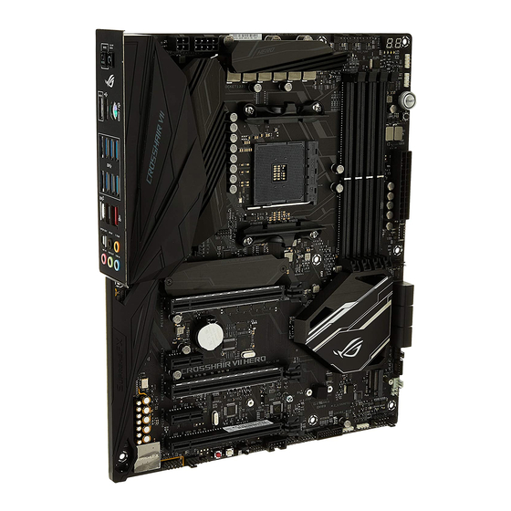
Page 18: Motherboard Layout
1.1.2 Motherboard layout Refer to 1.1.9 Internal connectors and 2.3.1 Rear I/O connection for more information about rear panel connectors and internal connectors. Chapter 1: Product Introduction... - Page 19 14. M.2 sockets (M.2_1; M.2_2) 1-25 15. System panel connectors (10-1 pin F_PANEL; 4-pin SPEAKER) 1-21 16. USB 3.1 Gen 1 connector (20-1 pin U31G1_910) 1-16 17. USB 2.0 connector (10-1 pin USB15; USB1112) 1-17 18. ROG extension connector (18-1 pin ROG_EXT) 1-18 19. LN2 Mode jumper (3-pin LN2_MODE) 1-12 20. Slow Mode Switch (SLOW_MODE) 1-11 21. ReTry button (RETRY_BUTTON) 1-10 22. Safe Boot button (SAFE_BOOT) 1-10 23. Thermal sensor connector (2-pin T_SENSOR1) 1-17 24. Front panel audio connector (10-1 pin AAFP) 1-18 25. LED connector (5-pin LED2_CON1) 1-24 ROG CROSSHAIR VII HERO (WI-FI)
-
Page 20: Central Processing Unit (Cpu)
1.1.3 Central Processing Unit (CPU) The motherboard comes with an AM4 socket designed for AMD Ryzen™ 2nd Generation / Ryzen™ 1st Generation / Ryzen™ with Radeon™ Vega Graphics / 7th Generation A-Series/ Athlon X4 Processors. The AM4 socket has a different pinout design. Ensure that you use a CPU designed for the AM4 socket. The CPU fits in only one correct orientation. DO NOT force the CPU into the socket to prevent bending the connectors on the socket and damaging the CPU! Ensure that all power cables are unplugged before installing the CPU. Chapter 1: Product Introduction... -
Page 21: System Memory
1.1.4 System memory The motherboard comes with four (4) Double Data Rate 4 (DDR4) Dual Inline Memory Modules (DIMM) slots. A DDR4 module is notched differently from a DDR, DDR2, or DDR3 module. DO NOT install a DDR, DDR2, or DDR3 memory module to the DDR4 slot. Recommended memory configurations ROG CROSSHAIR VII HERO (WI-FI) - Page 22 Memory configurations You may install 2 GB, 4 GB, 8 GB, and 16 GB unbuffered and non-ECC DDR4 DIMMs into the DIMM sockets. You may install varying memory sizes in Channel A and Channel B. The system maps the total size of the lower-sized channel for the dual-channel configuration. Any excess memory from the higher-sized channel is then mapped for single-channel operation. • The default memory operation frequency is dependent on its Serial Presence Detect (SPD), which is the standard way of accessing information from a memory module. Under the default state, some memory modules for overclocking may operate at a lower frequency than the vendor-marked value. • For system stability, use a more efficient memory cooling system to support a full memory load (4 DIMMs) or overclocking condition. • Always install the DIMMS with the same CAS Latency. For an optimum compatibility, we recommend that you install memory modules of the same version or data code (D/C) from the same vendor. Check with the vendor to get the correct memory modules. Chapter 1: Product Introduction...
-
Page 23: Expansion Slots
1.1.5 Expansion slots Unplug the power cord before adding or removing expansion cards. Failure to do so may cause you physical injury and damage motherboard components. Slot No. Slot Description PCIe 3.0 x16/x8_1 slot PCIe 2.0 x1_1 slot PCIe 3.0 x8/x4_2 slot PCIe 2.0 x1_2 slot PCIe 2.0 x4_3 slot ROG CROSSHAIR VII HERO (WI-FI) - Page 24 PCIe operating mode CPU Family M.2_1 M.2_1 PCIEX16/X8_1 PCIEX/X4_2 M.2_2 (PCIE mode) (SATA mode) Support AMD Ryzen™ 1st / 2nd Support Generation Processors Support AMD Ryzen™ with Radeon™ Support Vega Graphics Processors AMD 7th Generation Support A-Series / Athlon X4 Processors AMD Ryzen™...
-
Page 25: Onboard Buttons And Switches
1.1.6 Onboard buttons and switches Onboard buttons and switches allow you to fine-tune performance when working on a bare or open-case system. This is ideal for overclockers and gamers who continually change settings to enhance system performance. Power-on button (START) The motherboard comes with a power-on button that allows you to power up or wake up the system. The button also lights up when the system is plugged to a power source indicating that you should shut down the system and unplug the power cable before removing or installing any motherboard component. RESET button (RESET) Press the reset button to reboot the system. ROG CROSSHAIR VII HERO (WI-FI) - Page 26 Safe Boot button (SAFE_BOOT) The Safe Boot button can be pressed anytime to force the system to reboot into the BIOS safe mode. This button temporarily applies safe settings to the BIOS while retaining any overclocked settings allowing you to modify the settings causing boot failure. Use this button when overclocking or tweaking the settings of your system. ReTry button (RETRY_BUTTON) The ReTry button is specially designed for overclockers and is most useful during the booting process where the Reset button is rendered useless. When pressed, it forces the system to reboot while retaining the same settings to be retried in quick succession to achieve a successful POST. Chapter 1: Product Introduction 1-10...
- Page 27 Slow Mode Switch (SLOW_MODE) Slow Mode Switch is employed during LN2 benching. The system may crash due to the CPU being unstable when using extreme overclocking, enabling slow mode will decrease the processor frequency and stabilize the system, allowing overclockers to keep track of their overclocking data. ROG CROSSHAIR VII HERO (WI-FI) 1-11...
-
Page 28: Jumper
1.1.7 Jumper LN2 Mode jumper (3-pin LN2_MODE) With LN2 mode activated, the ROG motherboard is optimized to remedy the cold-boot bug during POST and help the system boot successfully. Chapter 1: Product Introduction 1-12... -
Page 29: Onboard Leds
1.1.8 Onboard LEDs Q LEDs (CPU, DRAM, VGA, BOOT) Q LEDs check key components (CPU, DRAM, VGA card, and booting devices) in sequence during motherboard booting process. If an error is found, the corresponding LED remains lit until the problem is solved. This user-friendly design provides an intuitive way to locate the root problem within seconds. The Q LEDs provide the most probable cause of an error code as a starting point for troubleshooting. The actual cause may vary from case to case. Hard Disk LED (HD_LED) The Hard Disk LED is designed to indicate the hard disk activity. It blinks when data is being written into or read from the hard disk drive. The LED does not light up when there is no hard disk drive connected to the motherboard or when the hard disk drive does not function. ROG CROSSHAIR VII HERO (WI-FI) 1-13... - Page 30 Q-Code LED The Q-Code LED design provides you with a 2-digit error code that displays the system status. Refer to the Q-Code table on the following page for details. • The Q-Code LED provides the most probable cause of an error code as a starting point for troubleshooting. The actual cause may vary from case to case. • Please refer to the Q-Code table in the Appendix section for more details. Chapter 1: Product Introduction 1-14...
-
Page 31: Internal Connectors
1.1.9 Internal connectors Serial ATA 6.0 Gb/s connectors (7-pin SATA6G_1-6) ® These connectors connect to Serial ATA 6.0 Gb/s hard disk drives via Serial ATA 6.0 Gb/s signal cables. If you installed Serial ATA hard disk drives, you can create a RAID 0, 1, and 10 configuration through the onboard AMD X470 chipset. ® • These connectors are set to [AHCI] by default. If you intend to create a Serial ATA RAID set using these connectors, set the SATA Mode Selection item in the BIOS to [RAID]. • Before creating a RAID set, refer to the RAID Configuration Guide. You can download the RAID Configuration Guide from the ASUS website. ROG CROSSHAIR VII HERO (WI-FI) 1-15... - Page 32 USB 3.1 Gen 2 front panel connector (U31G2_E1) This connector allows you to connect a USB 3.1 Gen 2 module for additional USB 3.1 Gen 2 ports. The latest USB 3.1 Gen 2 connectivity provides data transfer speeds of up to 10 Gbps. The next-generation standard is completely backward-compatible with your existing USB devices. USB 3.1 Gen 1 connector (20-1 pin U31G1_910) This connector allows you to connect a USB 3.1 Gen 1 module for additional USB 3.1 Gen 1 front or rear panel ports. With an installed USB 3.1 Gen 1 module, you can enjoy all the benefits of USB 3.1 Gen 1 including faster data transfer speeds of up to 5 Gbps, faster charging time for USB-chargeable devices, optimized power efficiency, and backward compatibility with USB 2.0. The USB 3.1 Gen 1 module is purchased separately. The plugged USB 3.1 gen 1 device may run on xHCI or EHCI mode depending on the operating system’s setting. Chapter 1: Product Introduction 1-16...
- Page 33 USB 2.0 connector (10-1 pin USB15; USB1112) These connectors are for USB 2.0 ports. Connect the USB module cable to any of these connectors, then install the module to a slot opening at the back of the system chassis. These USB connectors comply with USB 2.0 specification that supports up to 480 MBps connection speed. Never connect a 1394 cable to the USB connectors. Doing so will damage the motherboard! • 1 x USB 2.0 port (USB15) at mid-board shares with ROG extension (ROG_EXT) port. • The USB 2.0 module is purchased separately. Thermal sensor connector (2-pin T_SENSOR1) This connector is for the thermistor cable that allows you to monitor the temperature of your motherboard’s critical components and connected devices. ROG CROSSHAIR VII HERO (WI-FI) 1-17...
- Page 34 Front panel audio connector (10-1 pin AAFP) This connector is for a chassis-mounted front panel audio I/O module that supports HD Audio standard. Connect one end of the front panel audio I/O module cable to this connector. We recommend that you connect a high-definition front panel audio module to this connector to avail of the motherboard’s high-definition audio capability. ROG extension connector (18-1 pin ROG_EXT) This connector is for the OC Panel I/II. • The OC Panel I/II is purchased separately. • Support for OC Panel I/II varies over different platforms. • Visit www.asus.com for more information about the devices and the latest compatibility list. Chapter 1: Product Introduction 1-18...
- Page 35 Fan and pump connectors (4-pin CPU_FAN; 4-pin CPU_OPT; 4-pin H_AMP; 4-pin AIO_PUMP; 4-pin W_PUMP+; 5-pin EXT_FAN; 4-pin CHA_FAN1-3) Connect the fan cables to the fan connectors on the motherboard, ensuring that the black wire of each cable matches the ground pin of the connector. The EXT_FAN connector is only for the fan extension card. For more details on the fan extension card, please refer to the To install Fan Extension Card section in this guide. • DO NOT forget to connect the fan cables to the fan connectors. Insufficient air flow inside the system may damage the motherboard components. These are not jumpers! Do not place jumper caps on the fan connectors! • Ensure to fully insert the 4-pin CPU fan cable to the CPU fan connector. • For better Q-Fan functions, we recommend using 4-pin PWM fans when you connect powerful fans (1A or above) onto the H_AMP_FAN connector. • Ensure to disable Q-Fan functions if you want to connect powerful 3-pin DC fans (1A or above) onto the H_AMP_FAN connector. • Connect the pump cable from the all-in-one cooler (AIO cooler) to the AIO_PUMP header, and connect the fan cables to the CPU_FAN and/or CPU_OPT header(s). • W_PUMP+ function support depends on water cooling device. ROG CROSSHAIR VII HERO (WI-FI) 1-19...
- Page 36 Header Max. Current Max. Power Default Speed Shared Control CPU_FAN Q-Fan Controlled CPU_OPT Q-Fan Controlled CHA_FAN1 Q-Fan Controlled CHA_FAN2 Q-Fan Controlled CHA_FAN3 Q-Fan Controlled HAMP_FAN Q-Fan Controlled AIO_PUMP Full Speed W_PUMP+ Full Speed ATX power connectors (24-pin EATXPWR; 8-pin EATX12V_1; 4-pin EATX12V_2) These connectors are for ATX power supply plugs. The power supply plugs are designed to fit these connectors in only one orientation. Find the proper orientation and push down firmly until the connectors completely fit. • For a fully configured system, we recommend that you use a power supply unit (PSU) that complies with ATX 12 V Specification 2.0 (or later version) and provides a minimum power of 350 W.
-
Page 37: System Panel Connector 10-1 Pin F_Panel
System panel connectors (10-1 pin F_PANEL; 4-pin SPEAKER) These connectors supports several chassis-mounted functions. • System power LED (2-pin PLED) This 2-pin connector is for the system power LED. Connect the chassis power LED cable to this connector. The system power LED lights up when you turn on the system power, and blinks when the system is in sleep mode. • Hard disk drive activity LED (2-pin HDD_LED) This 2-pin connector is for the HDD Activity LED. Connect the HDD Activity LED cable to this connector. The HDD LED lights up or flashes when data is read from or written to the HDD. • System warning speaker (4-pin SPEAKER) This 4-pin connector is for the chassis-mounted system warning speaker. The speaker allows you to hear system beeps and warnings. • ATX power button/soft-off button (2-pin PWRBTN) This connector is for the system power button. Pressing the power button turns the system on or puts the system in sleep or soft-off mode depending on the BIOS settings. Pressing the power button for more than four seconds while the system is ON turns the system OFF. • Reset button (2-pin RESET) This 2-pin connector is for the chassis-mounted reset button for system reboot without turning off the system power. ROG CROSSHAIR VII HERO (WI-FI) 1-21... - Page 38 AURA RGB headers (4-pin RGB_HEADER1-2) These connectors are for RGB LED strips. The RGB header supports 5050 RGB multi-color LED strips (12V/G/R/B), with a maximum power rating of 3A (12V), and no longer than 3 m. Before you install or remove any component, ensure that the ATX power supply is switched off or the power cord is detached from the power supply. Failure to do so may cause severe damage to the motherboard, peripherals, or components. • Actual lighting and color will vary with LED strip. • If your LED strip does not light up, check if the RGB LED extension cable and the RGB LED strip is connected in the correct orientation, and the 12V connector is aligned with the 12V header on the motherboard. • The LED strip will only light up when the system is operating. • The LED strip is purchased separately. Chapter 1: Product Introduction 1-22...
- Page 39 Addressable RGB headers (4-1 pin ADD_HEADER1-2) These connectors are for individually addressable RGB WS2812B LED strips or WS2812B based LED strips. The addressable RGB header supports WS2812B addressable RGB LED strips (5V/Data/ Ground), with a maximum power rating of 3A (5V) and a maximum of 60 LEDs. Before you install or remove any component, ensure that the ATX power supply is switched off or the power cord is detached from the power supply. Failure to do so may cause severe damage to the motherboard, peripherals, or components. • Actual lighting and color will vary with LED strip. • If your LED strip does not light up, check if the addressable RGB LED strip is connected in the correct orientation, and the 5V connector is aligned with the 5V header on the motherboard. • The addressable RGB LED strip will only light up under the operating system. • The addressable RGB LED strip is purchased separately. ROG CROSSHAIR VII HERO (WI-FI) 1-23...
- Page 40 LED connector (5-pin LED2_CON1) This connector is for connecting LED strips on your cover. Water in, water out, and water flow connectors (2-pin W_IN; 2-pin W_OUT; 3-pin W_FLOW) These connectors allow you to connect sensors to monitor the temperature and flow rate of your liquid cooling system. You can manually adjust the fans and water pump to optimize the thermal efficiency of your liquid cooling system. Chapter 1: Product Introduction 1-24...
- Page 41 M.2 Socket (M.2_1; M.2_2) These sockets allow you to install M.2 SSD modules. • For AMD Ryzen™ 2nd Generation/Ryzen™ 1st Generation Processors, the M.2_1 supports PCIE 3.0 x4 and SATA mode M Key design and type 2242 / 2260 / 2280 / 22110 storage devices. The M.2_2 supports PCIE 3.0 x4 M Key design and type 2242 / 2260 / 2280 storage devices. • For AMD Ryzen™ with Radeon™ Vega Graphics Processors the M.2_1 supports PCIE 3.0 x4 and SATA mode M Key design and type 2242 / 2260 / 2280 / 22110 storage devices. • For AMD 7th Generation A-series/Athlon™ Processors, the M.2_1(SOCKET3) supports SATA mode M Key design and type 2242 / 2260 / 2280 / 22110 storage devices. The M.2 SSD module is purchased separately. ROG CROSSHAIR VII HERO (WI-FI) 1-25...
-
Page 42: Probeit
1.1.10 ProbeIt The ROG ProbeIt allows you to detect your system’s current voltage and OC settings. Use a multimeter to measure the ProbeIt points even during overclocking. See the illustration below to locate the respective ProbeIt points. Using ProbeIt You can connect the multimeter to the motherboard as shown on the following figure. The illustration above is for reference only, the actual motherboard layout and measure points may differ by model. Chapter 1: Product Introduction 1-26... -
Page 43: Chapter 2: Basic Installation
The AMD AM4 socket is compatible with AMD AM4 processors. Ensure you use a CPU designed for the AM4 socket. The CPU fits in only one correct orientation. DO NOT force the CPU into the socket to prevent bending the connectors on the socket and damaging the CPU! ROG CROSSHAIR VII HERO (WI-FI) -
Page 44: Cooling System Installation
2.1.2 Cooling system installation Apply the Thermal Interface Material to the CPU cooling system and CPU before you install the cooling system, if necessary. CPU heatsink and fan assembly Type 1 Chapter 2: Basic Installation... - Page 45 CPU heatsink and fan assembly Type 2 When using this type of CPU fan, remove the screws and the retention module only. Do not remove the plate on the bottom. ROG CROSSHAIR VII HERO (WI-FI)
- Page 46 To install an AIO cooler AIO_PUMP CPU_FAN CPU_OPT Chapter 2: Basic Installation...
-
Page 47: Motherboard Installation
Place the motherboard into the chassis, ensuring that its rear I/O ports are aligned to the chassis’ rear I/O panel. Place nine (9) screws into the holes indicated by circles to secure the motherboard to the chassis. DO NOT over tighten the screws! Doing so can damage the motherboard. ROG CROSSHAIR VII HERO (WI-FI) -
Page 48: Dimm Installation
2.1.4 DIMM installation To remove a DIMM Chapter 2: Basic Installation... -
Page 49: Atx Power Connection
ATX power connection • DO NOT connect the 4-pin power plug only, the motherboard may overheat under heavy usage. • Ensure to connect the 8-pin power plug, or connect both the 8-pin and 4-pin power plugs. ROG CROSSHAIR VII HERO (WI-FI) -
Page 50: Sata Device Connection
2.1.6 SATA device connection Chapter 2: Basic Installation... -
Page 51: Front I/O Connector
Push the connector until it clicks into place. To install USB 3.1 Gen 1 connector To install USB 2.0 connector USB 3.1 Gen 1 USB 2.0 To install front panel audio connector To install system speaker connector AAFP ROG CROSSHAIR VII HERO (WI-FI) -
Page 52: Expansion Card Installation
2.1.8 Expansion card installation To install PCIe x16 cards To install PCIe x1 cards Chapter 2: Basic Installation 2-10... - Page 53 The illustrations in this section are for reference only. The motherboard layout may vary with models, but the installation steps are the same for all models. • The FAN Extension card is purchased separately. ROG CROSSHAIR VII HERO (WI-FI) 2-11...
-
Page 54: Installation
2.1.9 M.2 installation Supported M.2 type varies per motherboard. For M.2_1 (Type 2260 / 2242 M.2) For M.2_1 (Type 2280 M.2) When installing a type 2280 M.2 to the M.2_1 slot without installing the heatsink, ensure to remove the pre-installed screw stand (A) and install the bundled tall screw stand (B). - Page 55 • Do not install the heatsink when installing a type 22110 M.2 to the M.2_1 slot. • Ensure to remove the pre- installed screw stand (A) and install the bundled tall screw stand (B). ROG CROSSHAIR VII HERO (WI-FI) 2-13...
- Page 56 For M.2_2 (Type 2260 / 2242 M.2) For M.2_2 (Type 2280 M.2) Ensure to use the bundled short screw stand. Chapter 2: Basic Installation 2-14...
-
Page 57: Wi-Fi Antenna Installation
2.1.10 Wi-Fi antenna installation Installing the ASUS 2x2 dual band W-Fi antenna Connect the bundled ASUS 2x2 dual band Wi-Fi antenna connector to the Wi-Fi ports at the back of the chassis. • Ensure that the ASUS 2x2 dual band Wi-Fi antenna is securely installed to the Wi-Fi ports. -
Page 58: Bios Update Utility
• Updating BIOS may have risks. If the BIOS program is damaged during the process and results to the system’s failure to boot up, please contact your local ASUS Service Center. Chapter 2: Basic Installation... -
Page 59: Motherboard Rear And Audio Connections
Please connect your USB 3.1 Gen 1 devices to USB 3.1 Gen 1 ports and your USB 3.1 Gen 2 devices to USB 3.1 Gen 2 ports for faster and better performance for your devices. ROG CROSSHAIR VII HERO (WI-FI) 2-17... - Page 60 * LAN ports LED indications ACT/LINK SPEED Activity Link LED Speed LED Status Description Status Description No link 10 Mbps connection ORANGE Linked ORANGE 100 Mbps connection LAN port BLINKING Data activity GREEN 1 Gbps connection ** Audio 2, 4, 5.1 or 7.1-channel configuration Headset Port 4-channel...
-
Page 61: Audio I/O Connections
2.3.2 Audio I/O connections Audio I/O ports Connect to Headphone and Mic Connect to Stereo Speakers Connect to 2-channel Speakers ROG CROSSHAIR VII HERO (WI-FI) 2-19... - Page 62 Connect to 4-channel Speakers Connect to 5.1-channel Speakers Connect to 7.1-channel Speakers Chapter 2: Basic Installation 2-20...
-
Page 63: Starting Up For The First Time
While the system is ON, press the power button for less than four seconds to put the system on sleep mode or soft-off mode, depending on the BIOS setting. Press the power button for more than four seconds to let the system enter the soft-off mode regardless of the BIOS setting. ROG CROSSHAIR VII HERO (WI-FI) 2-21... - Page 64 Chapter 2: Basic Installation 2-22...
-
Page 65: Chapter 3: Bios Setup
BIOS Setup Knowing BIOS The new ASUS UEFI BIOS is a Unified Extensible Interface that complies with UEFI architecture, offering a user-friendly interface that goes beyond the traditional keyboard- only BIOS controls to enable a more flexible and convenient mouse input. You can easily navigate the new UEFI BIOS with the same smoothness as your operating system. -
Page 66: Bios Setup Program
RTC RAM via the Clear CMOS button. • The BIOS setup program does not support the Bluetooth devices. Please visit ASUS website for the detailed BIOS content manual. BIOS menu screen The BIOS Setup program can be used under two modes: EZ Mode and Advanced Mode. -
Page 67: Advanced Mode
Language MyFavorite(F3) Qfan Control(F6) EZ Tuning Wizard(F11) AURA ON/OFF(F4) Menu items General help Go back to EZ Mode Hot Keys Last modified settings Search on the FAQ Displays a quick overview of the system status ROG CROSSHAIR VII HERO (WI-FI) - Page 68 Menu bar The menu bar on top of the screen has the following main items: For saving the frequently-used system settings and configuration. My Favorites For changing the basic system configuration Main For changing the overclocking settings Extreme Tweaker For changing the advanced system settings Advanced For displaying the system temperature, power status, and changing Monitor...
- Page 69 Move your mouse over this button to show a QR code, scan this QR code on your mobile device to connect to the BIOS FAQ web page of the ASUS support website. You can also scan the following QR code:...
-
Page 70: Ez Mode
3.2.2 EZ Mode The EZ Mode provides you an overview of the basic system information, and allows you to select the display language, system performance, mode and boot device priority. To access the Advanced Mode, select Advanced Mode or press the <F7> hotkey for the advanced BIOS settings. -
Page 71: Q-Fan Control
PWM Mode Select a profile to Click to apply the fan setting apply to your fans Click to undo the Click to go back to main menu changes Select to manually configure your fans ROG CROSSHAIR VII HERO (WI-FI) - Page 72 Configuring fans manually Select Manual from the list of profiles to manually configure your fans’ operating speed. Speed points Select to manually configure your fans To configure your fans: Select the fan that you want to configure and to view its current status. Click and drag the speed points to adjust the fans’...
-
Page 73: Ez Tuning Wizard
To start OC Tuning: Press <F11> on your keyboard or click from the BIOS screen to open EZ Tuning Wizard screen. Click OC then click Next. Select a PC scenario Daily Computing or Gaming/Media Editing, then click Next. ROG CROSSHAIR VII HERO (WI-FI) - Page 74 Select a Main Cooling System BOX cooler, Tower cooler, Water cooler, or I’m not sure, then click Next. After selecting the Main Cooling System, click Next then click Yes to start the OC Tuning. Chapter 3: BIOS Setup 3-10...
-
Page 75: My Favorites
My Favorites is your personal space where you can easily save and access your favorite BIOS items. My Favorites comes with several performance, power saving, and fast boot related items by default. You can personalize this screen by adding or removing items. ROG CROSSHAIR VII HERO (WI-FI) 3-11... - Page 76 Adding items to My Favorites To add BIOS items: Press <F3> on your keyboard or click from the BIOS screen to open Setup Tree Map screen. On the Setup Tree Map screen, select the BIOS items that you want to save in My Favorites screen.
-
Page 77: Main Menu
This item allows you to set the BCLK frequency to enhance the system performance. Use the <+> or <-> to adjust the value. We recommend you to set the value based on the CPU specification, as high BCLK frequencies may damage the CPU permanently. ROG CROSSHAIR VII HERO (WI-FI) 3-13... -
Page 78: Advanced Menu
Custom CPU Core Ratio This item allows you to set a custom CPU core ratio. The CPU core ratio is calculated with the formula: 2 * FID / DID. Configuration options: [Auto] [Manual] The following items appear only when you set the Custom CPU Core Ratio to [Manual]. This item allows you to set the core frequency multiplier. -
Page 79: Cpu Configuration
[RAID] Set to [RAID] when you want to create a RAID configuration from the SATA hard disk drives. ROG CROSSHAIR VII HERO (WI-FI) 3-15... -
Page 80: Onboard Devices Configuration
SMART Self Test S.M.A.R.T. (Self-Monitoring, Analysis and Reporting Technology) is a monitoring system that shows a warning message during POST (Power-on Self Test) when an error occurs in the hard disks. Configuration options: [On] [Off] SATA6G_1(Black) - SATA6G_6(Black) SATA6G_1 - SATA6G_6 This item allows you to enable or disable the selected SATA port. - Page 81 Wi-Fi Controller This item allows you to enable or disable the Wi-Fi controller. Configuration options: [Disabled] [Enabled] Bluetooth Controller This item allows you to enable or disable the Intel Bluetooth controller. Configuration options: [Disabled] [Enabled] ROG CROSSHAIR VII HERO (WI-FI) 3-17...
-
Page 82: Apm Configuration
3.6.6 APM Configuration The items in this menu allow you to set system wake and sleep settings. ErP Ready [Disabled] This item allows you to switch off some power at S4+S5 or S5 to get the system ready for ErP requirement. When set to [Enabled], all other PME options are switched off. Configuration options: [Disabled] [Enable(S4+S5)] [Enable(S5)] Restore On AC Power Loss This item allows your system to go to ON state, OFF state, or both states after an AC power... -
Page 83: Usb Configuration
Detects the type of water pump installed and automatically switches the control modes. [DC mode] Enable the Water Pump control in DC mode for 3-pin chassis fan. [PWM mode] Enable the Water Pump control in PWM mode for 4-pin chassis fan. ROG CROSSHAIR VII HERO (WI-FI) 3-19... -
Page 84: Boot Menu
Boot menu The Boot menu items allow you to change the system boot options. Fast Boot [Disabled] Allows your system to go back to its normal boot speed. [Enabled] Allows your system to accelerate the boot speed. The following item appears only when you set the Fast Boot to [Enabled]. Next Boot after AC Power Loss [Normal Boot] Returns to normal boot on the next boot after an AC power loss. -
Page 85: Tool Menu
3.9.1 ASUS EZ Flash 3 Utility This item allows you to run ASUS EZ Flash 3. When you press <Enter>, a confirmation message appears. Use the left/right arrow key to select between [Yes] or [No], then press <Enter> to confirm your choice. -
Page 86: Asus Secure Erase
To launch ASUS Secure Erase, click Tool > ASUS Secure Erase on the Advanced mode menu. Check the ASUS support site for a full list of SSDs tested with ASUS Secure Erase. The drive may become unstable if you run ASUS Secure Erase on an incompatible SSD. -
Page 87: Asus User Profile
This item allows you to load the previous values of the CPU Core Voltage, VCCSA Voltage, BCLK Frequency, CPU ratio, and Cache ratio. 3.9.5 ASUS SPD Information This item allows you to view the DRAM SPD information. ROG CROSSHAIR VII HERO (WI-FI) 3-23... -
Page 88: Graphics Card Information
This item displays the information and recommended configuration for the PCIE slots that the graphics card is installed in your system. This feature is only supported on selected ASUS graphics cards. Bus Interface This item allows you to select the bus interface. -
Page 89: Updating Bios
® ASUS EZ Flash 3: Updates the BIOS using a USB flash drive. ASUS CrashFree BIOS 3: Restores the BIOS using the motherboard support DVD or a USB flash drive when the BIOS file fails or gets corrupted. 3.11.1... -
Page 90: Asus Ez Flash 3
3.11.2 ASUS EZ Flash 3 ASUS EZ Flash 3 allows you to download and update to the latest BIOS through the Internet without having to use a bootable floppy disk or an OS-based utility. Updating through the Internet varies per region and Internet conditions. Check your local Internet connection before updating through the Internet. - Page 91 To update the BIOS by Internet: Enter the Advanced Mode of the BIOS setup program. Go to the Tool menu to select ASUS EZ Flash Utility and press <Enter>. Select via Internet. Press the Left/Right arrow keys to select an Internet connection method, and then press <Enter>.
-
Page 92: Asus Crashfree Bios 3
The BIOS file in the motherboard support DVD may be older than the BIOS file published on the ASUS official website. If you want to use the newer BIOS file, download the file at https://www.asus.com/support/ and save it to a USB flash drive. -
Page 93: Chapter 4: Raid Support
The motherboard comes with the RaidXpert2 Configuration Utility that supports Volume, RAIDABLE, RAID 0, RAID 1, and RAID 10 (depends on system licensing) configurations. For more information on configuring your RAID sets, please refer to the RAID Configuration Guide which you can find at https://www.asus.com/support. 4.1.1 RAID definitions Volume provides the ability to link-together storage from one or several disks, regardless of the size of the space on those disks. - Page 94 Chapter 4: RAID Support...
-
Page 95: Appendix
CPU self test failed or possible CPU cache error CPU micro-code is not found or micro-code update is failed Internal CPU error Reset PPI is not available Reserved for future AMI error codes 5C – 5F (continued on the next page) ROG CROSSHAIR VII HERO (WI-FI) -
Page 96: Q-Code Table
Q-Code table Code Description S3 Resume is stared (S3 Resume PPI is called by the DXE IPL) S3 Boot Script execution Video repost OS S3 wake vector call Reserved for future AMI progress codes E4 – E7 S3 Resume Failed S3 Resume PPI not Found S3 Resume Boot Script Error S3 OS Wake Error... - Page 97 Reserved for ASL (see ASL Status Codes section below) Ready To Boot event Legacy Boot event Exit Boot Services event Runtime Set Virtual Address MAP Begin Runtime Set Virtual Address MAP End Legacy Option ROM Initialization System Reset (continued on the next page) ROG CROSSHAIR VII HERO (WI-FI)
- Page 98 Q-Code table Code Description USB hot plug PCI bus hot plug Clean-up of NVRAM Configuration Reset (reset of NVRAM settings) B8– BF Reserved for future AMI codes CPU initialization error System Agent initialization error PCH initialization error Some of the Architectural Protocols are not available PCI resource allocation error.
-
Page 99: Notices
The use of shielded cables for connection of the monitor to the graphics card is required to assure compliance with FCC regulations. Changes or modifications to this unit not expressly approved by the party responsible for compliance could void the user’s authority to operate this equipment. ROG CROSSHAIR VII HERO (WI-FI) - Page 100 Compliance Statement of Innovation, Science and Economic Development Canada (ISED) This device complies with Innovation, Science and Economic Development Canada licence exempt RSS standard(s). Operation is subject to the following two conditions: (1) this device may not cause interference, and (2) this device must accept any interference, including interference that may cause undesired operation of the device.
- Page 101 ASUS Recycling/Takeback Services ASUS recycling and takeback programs come from our commitment to the highest standards for protecting our environment. We believe in providing solutions for you to be able to responsibly recycle our products, batteries, other components as well as the packaging materials.
- Page 102 FCC Bluetooth Wireless Compliance The antenna used with this transmitter must not be co-located or operated in conjunction with any other antenna or transmitter subject to the conditions of the FCC Grant. Bluetooth Industry Canada Statement This Class B device meets all requirements of the Canadian interference-causing equipment regulations.
- Page 103 Unless required by applicable law or agreed to in writing, software distributed under the License is distributed on an “AS IS” BASIS, WITHOUT WARRANTIES OR CONDITIONS OF ANY KIND, either express or implied. See the License for the specific language governing permissions and limitations under the License. ROG CROSSHAIR VII HERO (WI-FI)
- Page 104 2014/53/EU. Cijeli di: https://www.asus.com/support/ tekst EU izjave o sukladnosti dostupan je na https://www.asus.com/support/ WiFi yang Beroperasi pada 5150-5350 MHz akan terbatas untuk penggunaan WiFi koji radi na opsegu frekvencija 5150-5350 MHz bit će ograničen na...
- Page 105 ASUSTek Computer Inc. tukaj izjavlja, da je ta naprava skladna s temeljnimi zahtevami in drugimi relevantnimii določili Direktive 2014/53/EU. Polno besedilo izjave EU o skladnosti je na voljo na https://www.asus.com/support/ WiFi, ki deluje v pasovnem območju 5150–5350 MHz, mora biti v državah, navedenih v spodnjem seznamu, omejen na notranjo uporabo: Declaración de conformidad simplificada para la UE...
-
Page 106: Asus Contact Information
+1-510-608-4555 Web site http://www.asus.com/us/ Technical Support Support fax +1-812-284-0883 Telephone +1-812-282-2787 Online support https://www.asus.com/support/Product/ContactUs/ Services/questionform/?lang=en-us ASUS COMPUTER GmbH (Germany and Austria) Address Harkort Str. 21-23, 40880 Ratingen, Germany +49-2102-959931 Web site http://www.asus.com/de Online contact http://eu-rma.asus.com/sales Technical Support Telephone +49-2102-5789555 Support Fax... - Page 107 CA 94539. Phone/Fax No: (510)739-3777/(510)608-4555 hereby declares that the product Product Name : Motherboard Model Number : ROG CROSSHAIR VII HERO (WI-FI), ROG CROSSHAIR VII HERO Conforms to the following specifications: FCC Part 15, Subpart B, Unintentional Radiators Supplementary Information: This device complies with part 15 of the FCC Rules.
- Page 108 A-14 Appendix...
Need help?
Do you have a question about the rog crosshair vii hero and is the answer not in the manual?
Questions and answers