Table of Contents
Advertisement
USERS MANUAL / GEBRUIKERSHANDLEIDING / BETRIEBSANLEITING
MANUEL D'UTILISATION / MANUAL DE UTILIZACION
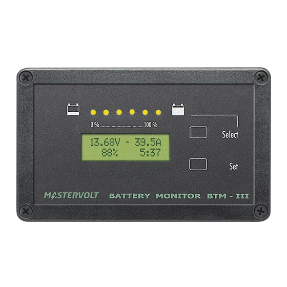
Masterlink BTM III
Monitor for three independent battery sets
MASTERVOLT
Snijdersbergweg 93,
1105 AN Amsterdam
The Netherlands
Tel.: +31-20-3422100
Fax.: +31-20-6971006
www.mastervolt.com
25.54V - 29.3A
42%
25:14
ENGLISH:
NEDERLANDS:
DEUTSCH:
FRANÇAIS:
CASTELLANO:
v 4.2 November 2006
PAGE 1
PAGINA 37
SEITE 73
PAGINA 109
PÁGINA 145
Advertisement
Table of Contents

Related Manuals for Mastervolt Masterlink BTM III


Summary of Contents for Mastervolt Masterlink BTM III
- Page 1 USERS MANUAL / GEBRUIKERSHANDLEIDING / BETRIEBSANLEITING MANUEL D’UTILISATION / MANUAL DE UTILIZACION Masterlink BTM III Monitor for three independent battery sets 25.54V - 29.3A 25:14 ENGLISH: PAGE 1 NEDERLANDS: PAGINA 37 MASTERVOLT DEUTSCH: SEITE 73 Snijdersbergweg 93, FRANÇAIS: PAGINA 109...
-
Page 2: Quick Review
QUICK REVIEW QUICK REVIEW The Masterlink BTM-III is the “fuel gauge” for up to three battery banks The LED bar shows how full the main battery set is (bank 1): each LED represents 16%. This green LED indicates that the main batteries are full (96-100%). (chapter 11.4) Touch Select shortly to scroll through... -
Page 3: Table Of Contents
Guarantee specifications ........................6 Quality..............................6 Validity of this manual......................... 6 Liability..............................6 Changes to the Masterlink BTM III ..................... 6 SAFETY GUIDELINES AND MEASURES ..................... 7 Warnings and symbols ........................7 Use for intended purpose ........................7 Organizational measures........................7 Maintenance and repair ........................ - Page 4 CONTENTS HISTORICAL DATA MENU .......................... 18 Time since start-up ........................... 18 Time since last low battery alarm ..................... 18 Time since last full charge ........................ 18 Cycles count ............................. 18 Abuse cycles............................. 18 Discharged time..........................19 Calculated value for the CEF......................19 Total Ampere hours consumed ......................
- Page 5 CONTENTS SETTINGS MENU ............................24 10.1 Lock mode ............................24 10.2 Language............................24 10.3 Engergy save mode.......................... 24 10.4 Charge Efficiency Factor battery Bank 1 ..................24 10.5 Peukert Exponent battery bank 1 ..................... 25 10.6 Reset historical data battery bank 1 ....................25 10.7 Charge amps for full battery ......................
-
Page 6: General Information
Masterlink BTM III delivered by Mastervolt. It is therefore obligatory that every person who works on or with the Masterlink BTM III must be LIABILITY completely familiar with the contents of this manual, Mastervolt can accept no liability for: and that he/she carefully follows the instructions •... -
Page 7: Safety Guidelines And Measures
• observing the instructions in the users accordance with local standards. • Do not work on the Masterlink BTM III or system manual. if it is still connected to a current source. Only WARNING... -
Page 8: Operation
25:14 LCD display Set button Figure 1: operation of the Masterlink BTM-III INTRODUCTION FEATURES • Monitoring of three independent battery banks Mastervolt Masterlink BTM-III provides extended information about the status of your (12/24V DC) • Easy installation batteries. This information includes reading voltage, •... -
Page 9: Lcd Display
OPERATION LCD DISPLAY SET/SELECT-BUTTONS The Masterlink BTM-III offers several menus to 25.54V - 29.3A adjust settings. Navigation through these menus and 25:14 the adjustment of parameters is done by means of Figure 2: initial menu the Select- and Set- button. There is a distinction between pressing the Select- The actual status and user specific information of the and Set- button for a short and a long time:... -
Page 10: Installation
Check with a suitable voltmeter whether the entire DC installation is voltage free. Mounting of the panel The Masterlink BTM III panel should be placed as close as possible to the batteries. Maximum distance: 25 meters. • Make a cut out in the instrument panel using the outline drawings of chapter 13 or using the mounting template of the box in which the Masterlink BTM III was delivered. - Page 11 – connected at the load side of the shunt Battery side Load side Connect the Masterlink BTM III as indicated below, but do not place the 2A-T fuses of the voltage sense wires yet! Masterlink BTM III Rear view LOW BATT RLY...
- Page 12 SHUNT LOAD SIDE GROUND dashboard lightning. + POWER SUPPLY Masterlink BTM III See chapter 9.1 for settings Rear view Option: Here a 6-pole RJ12 connector can be found for serial communication. Protocol QRS232. See chapter 11.6 for more information Check all wiring.
-
Page 13: First Start-Up
Press Select 4 times: more extended Select SETTINGS is shown. 4 times See chapter 9 and 10 for more information about configuration of the Masterlink BTM III. SETTINGS SET TO ENTER Then press Set to enter 5.2.1 Adjustment of values the settings menu. -
Page 14: Settings For Battery Bank 1 (Service Battery)
FIRST START-UP 5.2.2 Settings for battery bank 1 (Service battery) Now BANK VOLTAGE is displayed BANK VOLTAGE The following parameters must be adjusted for the service battery (battery bank 1): • Name of the battery bank; example: POWER If necessary, press Set BANK to adjust. -
Page 15: Settings For Battery Bank 2 And 3
FIRST START-UP 5.2.3 Settings for battery bank 2 and 3 Now BANK VOLTAGE is displayed (If The following parameters must be adjusted for necessary press Set to BANK VOLTAGE battery banks 2 and 3: adjust) • Name of the battery bank; example: BOWTHRUST BANK •... -
Page 16: Main Menu
MAIN MENU 6 MAIN MENU This chapter describes the functions of the main menu. If none of the buttons was touched for 60 seconds, the Masterlink BTM-III automatically returns to this menu .It offers a quick status overview of the battery banks. It is immediately accessible by pressing Select shortly. -
Page 17: Navigation Through The Submenus
NAVIGATION THROUGH THE SUBMENUS 7 NAVIGATION THROUGH THE SUBMENUS From the Main Menu of the Masterlink BTM-III several submenus can be accessed for adjustment of settings CAREFUL! Invalid settings of the Masterlink BTM-III can cause serious damage to your batteries. Adjustments of settings may be undertaken by authorised personnel only! From the main menu (see chapter 6), hold Select pressed for approximately 3 seconds to get access to the submenus. -
Page 18: Historical Data Menu
60 seconds, the display returns to the main menu (chapter 6) automatically TIME SINCE START-UP DAYS RUNNING This function displays the total number of days since the Masterlink BTM III was XXXXX powered. See chapter 10.6 if you want to reset this value. -
Page 19: Discharged Time
HISTORICAL DATA MENU DISCHARGED TIME DISCHARGED HRS This screen shows the total number of hours (after a delay of 12 hours) when the XXXXXh SOC of battery bank 1 was below 20% SOC. This value should be as low as Select possible, as batteries should be recharged immediately after a discharge. -
Page 20: Deepest Discharge Battery Bank 2
HISTORICAL DATA MENU 8.12 DEEPEST DISCHARGE BATTERY BANK 2 BANK 2 LOWEST Shows the lowest voltage that was recorded. This value should never be below the XX.XV final discharge voltage as specified by the battery manufacturer. Not shown if Select BATTERY NAME is set to “NOT USED”... -
Page 21: Battery Bank Menus 1, 2 And 3
BATTERY BANK MENUS 1, 2 AND 3 9 BATTERY BANK MENUS 1, 2 AND 3 This menu is used to adjust the Masterlink BTM-III according to the voltage and capacity of the batteries. The way settings are made is almost identical for each of the battery sets. Any differences are described in the sections below. -
Page 22: Average Discharge Amps
BATTERY BANK MENUS 1, 2 AND 3 AVERAGE DISCHARGE AMPS AVERAGE LOAD Only displayed for battery bank 2 and 3 and only shown if visualisation of SOC 2 + 3 is enabled (see chapter 10.16). For a more accurate calculation of the State Of Charge the expected average Select discharge Amps must be entered. -
Page 23: State Of Charge Level For "Full Battery
BATTERY BANK MENUS 1, 2 AND 3 9.11 STATE OF CHARGE LEVEL FOR “FULL BATTERY” SOC FULL If the state of charge rises above this level, the battery is considered to be almost full. At this level the battery alarm function switches off again Select Note for battery bank 2 and 3: only shown if visualisation of SOC 2 + 3 is enabled (see chapter 10.16) -
Page 24: Settings Menu
SETTINGS MENU 10 SETTINGS MENU The Settings Menu is used to adjust general settings like displayed language, energy save mode and advanced settings for each battery bank. Here you also have the possibility to reset the Masterlink BTM-III back to the factory settings Refer to chapter 7 to get access to this menu Touch Select shortly to scroll through the levels as described below. -
Page 25: Peukert Exponent Battery Bank 1
See also chapter 11.4 for additional information. Factory setting: 13.2V/26.4V depending on the nominal battery voltage. When a Mastervolt battery charger is applied, you don’t need to change this value. Adjustable range: 12.0…14.0V/24.0…28.0V EN / Masterlink BTM-III / November 2006... -
Page 26: Battery Bank 1: No Shunt
SETTINGS MENU 10.9 BATTERY BANK 1: NO SHUNT NO SHUNT For the most accurate readout of the battery bank 1 the use of a shunt is mandatory. If it is not possible to use a shunt, this setting must be switched to ON. If switched to ON, functions and specifications of battery bank 1 are as indicated for battery bank 2 Select Factory setting: OFF... -
Page 27: Reset To Factory Settings
SETTINGS MENU 10.17 RESET TO FACTORY SETTINGS RESET TO FACT. Here all settings will be reset to the original factory settings when Set is held for PRESS SET 3S three seconds. Select 10.18 SOFTWARE VERSION SOFTWARE VER. This level shows the installed software version; this value cannot be changed 0.00 Select 10.19 NMAE OUT: ON/OFF... -
Page 28: Additional Information
ADDITIONAL INFORMATION 11 ADDITIONAL INFORMATION 11.1 BATTERY ALARM FUNCTION Battery voltage 100% State of Charge SOC FULL LOW VOLTAGE 11,0/22,0V alarm function SOC EMPTY activated Time ALARM DELAY MIN RUN TIME Figure 3: Adjustments of the battery alarm function MAX RUN TIME The Masterlink BTM-III continuously monitors the The Alarm function is switched off again if one of the state of charge of the batteries. -
Page 29: Peukert Exponent
ADDITIONAL INFORMATION the lifetime of the battery the efficiency will slowly 11.4 STATE OF CHARGE. decline depending on its age and the number of The state of charge (see chapter 6) is expressed as discharge cycles. If an efficiency of 70 % is reached, percentage. -
Page 30: Masteradjust Software
PC-Link cable can be used to monitor and configure different Mastervolt products, including the Masterlink BTM III. It allows you to read the measured data from your Masterlink BTM-III battery monitor and store these data to a file. With this file you can analyze the performance of your DC system and your batteries in particular. -
Page 31: Battery Names
Mastervolt can offer a wide range of products for your electrical installation, including AGM batteries, GEL batteries, DC distribution kits, battery switches, battery cables, battery terminals and Mastervision switchboards See our website www.mastervolt.com for an extensive overview of all our products and free to download software for remote monitoring (see chapter 11.6) -
Page 32: Trouble Shooting
TROUBLE SHOOTING 12 TROUBLE SHOOTING Contact your local Mastervolt Service Centre if you cannot correct a problem with the aid of the malfunction table below. See www.mastervolt.com for an extended list of Mastervolt Service Centres. Failure Possible cause What to do... - Page 33 TROUBLE SHOOTING Failure Possible cause What to do SOC not displayed for Visualisation of SOC for See chapter 10.16 to enable the visualisation of battery bank 2 or 3 battery bank 2 + 3 is set to SOC for battery bank 2 + 3 “OFF”...
-
Page 34: Specifications
Delivery includes: Panel, grey installation housing, shunt, user’s manual Function of instrument Battery monitor for three independent battery banks (12/24V DC) Manufacturer Mastervolt Amsterdam the Netherlands Number of battery sets Voltage Measurement 7-35 V (0.1V resolution) Voltage accuracy ± 0,6 % ± 1 digit Current Measurement 0-500 A, 0.2A resolution (0…42A) 2A resolution (42…500A) -
Page 35: Dimensions
SPECIFICATIONS 13.2 DIMENSIONS Fig. 6: dimensions of the grey installation cover All dimensions are in mm Fig. 7: dimensions of the Masterlink BTM panel All dimensions are in mm EN / Masterlink BTM-III / November 2006... -
Page 36: Ec Declaration Of Confirmity
1105 AN Amsterdam The Netherlands Herewith declares that: Product: 70403163 Masterlink BTM III (12/24V) Is in conformity with the provision of the EC EMC directive 89/336/EEC and amendments 92/31/EEC, 93/68/EEC. The following harmonised standards have been applied: Generic emission standard: EN 50081-1:1992...
Need help?
Do you have a question about the Masterlink BTM III and is the answer not in the manual?
Questions and answers